the HSPR with six-controlled degree of freedom is presented. In the virtual design works by DADS (a dynamic analysis software), workspace and force analysis are discussed. We determine the hard points of a base and a platform. Also, the ranges of permissible extension of the struts are calculated.
1. INTRODUCTION
Design of a Hybrid Serial-Parallel Robot
for Multi-Tasking Machining Processes (ICCAS 2005)
Jin-Ho Kyung*, Hyung-Suk Han*, Young-Ho Ha**, Gwang-Jo Chung*
*Intelligence & Precision Machine Dept. Korea Institute of Machinery and Materials, P.O.Box 101, Yusung, Taejon 305-600, Korea(Tel : +82-42-868-7885; E-mail: [email protected])
** Gyeongnam Future Industry Foundation 4-1, Youngho-dong, Changwon, Korea (Tel : +82-055-262-9400; E-mail: [email protected])
Abstract: This paper presents a new hybrid serial-parallel robot(HSPR), which has six degrees of freedom driven by ball screw linear actuators and motored joints. This hybrid robot design presents a compromise between high rigidity of fully parallel manipulators and extended workspace of serial manipulators. The hybrid robot has a large, singularity-free workspace and high stiffness. Therefore, the presented kinematic structure of the hybrid robot is particularly suitable for multi-tasking machining processes such as milling, drilling, deburring and grinding. In addition to the machining processes, the hybrid robot can be used for welding, fixturing, material handling and so on. The study on design of the hybrid robot is performed. A kinematic analysis and mechanism description of the hybrid robot with six-controlled degree of freedom is presented. In the virtual design works by DADS, workspace and force analysis are discussed. A numerical model is treated to demonstrate our analysis and to determine the range of permissible extension of the struts. Also, we determine some important design parameters for the hybrid robot.
Keywords: hybrid serial-parallel robot, multi-tasking machining, kinematic analysis, virtual design
Nowadays multi-tasking machines attract the attention of the markets in machining industry because the machines can solve the real issues such as the production of diversified parts in small lots, quick delivery, cost cutting, the production of complex shape components for weight savings and multi-functions and serious shortage of skilled workers and experiences. Also, the machines can make strengthen machining efficiencies and enhance the added values of the machine tools[1,2,3].
2. MODELLING OF HSPR
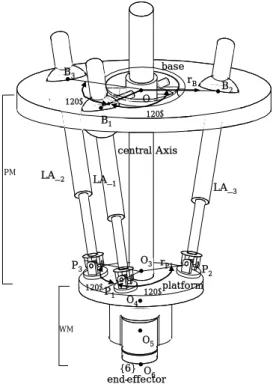
Figure 1 shows the virtual model of HSPR designed by DADS. This model is composed of a fixed base, a moving platform, an endeffector and several joints in series. The platform is linked to the fixed base by three struts in parallel. Its motion is restricted to only three degrees of freedom using three SPU joints linking the platform to the base. The endeffector is linked to the platform by three motored joints in serial. This design presents the particularity of having the size of the orientation workspace independent of the position of the platform, unlike the fully parallel mechanisms. This characteristic is achieved by separating the actuators responsible of the linear displacement of the platform. The endeffector has 6 degrees of freedom with respect to the base. A flexible joint, which give a prismatic guidance and transfer the torque, is installed in a center strut, and reduce the equivalent mass of the endeffector in order to improve the dynamic performance.
Compared with conventional machine tools, parallel kinematic robots have higher stiffness-to-mass ratio, higher speeds, higher accuracy, reduced installation requirements, and mechanical simplicity in order to give efficient solutions to multi-tasking machining problems. The first industrial application model of a parallel kinematic robot as machine tools for multi-tasking machining was addressed at IMTS in Chicago 1994. Subsequently several machine tool makers around the world had developed their own parallel kinematic robots for machine tools. The most of the parallel kinematic robots were based on the paradigm of the parallel kinematic structure, developed by Steward in 1965[4]. Steward platform present a high rigidity compared with serial manipulators. However, most of the authors have pointed out the major drawback of Steward platform, which is its limited workspace[1]. The novel Stewart like mechanism, which extends workspace was studied by Romdhane[5]. His mechanism is made of a base and two parallel platforms in series.
In this work we suggests a hybrid serial-parallel robot(HSPR) mechanism that presents a compromise between the high rigidity of parallel kinematic structures and the extended workspace of serial kinematic structures. This mechanism is made of a base, a platform and an endeffector in series. The procedure for design of the HSPR mechanism is
presented. A kinematic analysis and mechanism description of
joints are passive but only one prismatic joint is active to extend or shorten the length of a linear actuator. Points Bi
and Pi for i=1,2,3, are affixed symmetrically 120° apart to the
base and the platform, respectively, with ||
i
B
O0 || =rB , The schematic diagram of HSPR for theoretical analysis is shown in Figure 2. The HSPR with linear actuation places a movable platform (platform) at a desired position by three ball screw linear actuators (LA_i, i=1,2,3) attached to a stationary base (base). Linear actuators, LA_i for i=1,2,3, are attached to B_i through spherical joints and connected to Pi through
universal joints establishing link trains, which joint variables are represented by θij for j=1,2,..,6 (see Figure 3). Five rotary
θi5 θi6 platform θi4 θi2 θi1 θi3 θ3 θ6 O6 spline shaft ^ X6 ^ Y6 ^Z6 θ2 θ1 θ5 θ4 O4 O5 ^ X5 ^ Y5 ^Z5 ^ X4 ^ Y4 ^Z4 ^ Y0 ^ X0 ^ Z0 base platform O0 base Linear Actuator µ1 µ2 µ3 {0} {4} O3 ^ Y3 Z^3 ^ X3 µ4 µ5 µ6 {3} {5} {6} || i P 3
O ||=rP. Points Oi for i=0,3 are the central points of the
base and the platform, respectively. Purpose of a center strut, possessing one prismatic and two universal joints (see Figure 3), is to constrain the parallel robot permitting its d.o.f., i.e., three in the parallel robot. Adding the several joints with three rotary actuators on the platform makes the HSPR to have six d.o.f[6]
Fig. 3 Linear actuator and Center strut
3. KINEMATIC ANALYSIS AND SIMULATIONS
3.1 Kinematic analysis[6]
Fig. 1 The virtual design model of HSPR by DADS The Inverse kinematics of the HSPR is formulated to find active joint displacements for a given pose (a position and orientation) of tool. As shown in Figure 3, frames {0} assigned to the base, {3} and {4} to platform, and {5} and {6} to the WM and tool, with their origins at Oi for i=0,3,4,5,6: the
z-axis of frame {0}, Zo, is downward being perpendicular to
the base, the x-axis, Xo, is aligned with µ1, and the y-axis, Yo,
is determined by a right hand rule, and the other three axes, Zi,
Yi, Zi for i=4,5,6, are the same directions as those of the frame
{0} at a zero position, i.e., θi =0 for i=1,2,..,6.
O O6 central Axis O4 O5 platform base B1 B2 B3 120Λ rB PM 120Λ O3 rP1 end-effector 120ΛP 120Λ 1 P2 P3 WM O0 LA_2 LA_ 1 LA_ 3 O {6}
When the position vector from point O0 to O6, O0O6
6
R , and the orientation of frame {6} with respect to {0}, 0 , are given, θi for i=1,2,..,6 can be calculated by the following
equations :
[θ1 θ2 θ3 θ4 θ5 θ6 ] T = Kc−1(O0O6,
0 ) (1) 6
R
where () is the inverse kinematics function of the central axis similar to a serial robot. θ
1 −
c
K
1,θ2 and θ3 are passive joints
generating by three active joint θi3 of each LA_i. For the
closed loops O0Bi Pi O3 for i=1,2,3 in the PM, BiPi, is described by θi1, θi2 and θi3, O0O3 and are represented by θ
3 0
R
1,θ2 and θ3. Referring to (1), we have
||BiPi||= ||O0O3 - O0Bi+ 3 0
R O3Pi|| (i=1, 2, 3) (2).
Fig. 2 The schematic diagram of HSPR
The direct kinematics is formulated to find a pose (a position and orientation) of tool for a given active joint displacements. Since the equations (2) are expressed in implicit forms, θi for
i=1, .. , 6are obtained by Newton's numerical method. 3.2 Workspace investigation
The required workspace for the HSPR is
φ
800 * 600 mm2. Figure 4 shows the coordinate system for workspacecalculation. For various R1(equals to rB ) and R2(equals to rP )
(refer to Table 1), the workspaces were calculated by simulation. The structure parameters of the HSPR at the initial conditions are given as:rB = 500 mm, rP = 250 mm and
minimum length of the centre strut is 900 mm. The limits of the linear drives are given by: 900 mm ≤LAi≤1,700 mm(i=1, 2,
3). The limits of rotational angle of the joints Bi and Pi are
-45˚≤θ≤45˚(i=1, 2, 3).
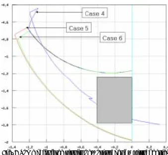
The simulation results show that the proposed HSPR has a large singularity free workspace, shown in Figure 5-7. In these figures, the axi-symmetric areas(m2) in X-Z plane, which the
point P(endeffector in figure 4) can travel around, are presented as R1 and R2 vary. The area inside the rectangle is the required workspace, and from the pictures it can be seen that the workspace of the proposed HSPR is much bigger than the required workspace.
Fig. 5 Some calculated results of workspaces by virtual design method using DADS.
Fig. 4 The coordinate systems for workspace calculation.
Table 1 Some cases for variation of R1 and R2. Fig. 6 Some calculated results of workspaces by virtual design method using DADS.
Fig. 7 Some calculated results of workspaces by virtual design method using DADS.
3.3 Reaction force investigation 0.0 0.4 0.8 1000 1200 1400 1600 1800 2000 2200 2400 2600 2800 3000 Spheric al joint forc e( N) Actuator extention(m) Case 1 Case 2 Case 3 Case 4 Case 5 Case 6 Case 7 Case 8 Case 9
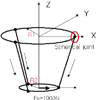
The main advantage of the HSPR is that it can offer the required force for machining with high stiffness. To investigate the forces, a suggested model of the HSPR has been built in DADS. Table 2 gives some cases for variation of R1 and R2. A selection force(Fx = 1,000 N) actuates on the centre of the platform at the initial position(refer to Figure 8). Figure 8 shows the coordinate system for reaction force calculation. For various R1 and R2(refer to Table 2), the reaction force were calculated by simulation by virtual design simulation.
The simulation results(refer to Figure 9) show that the maximum reaction force of joints takes place in the joint described with a circle shown in Figure 8. The reaction forces are not sensitive to the variations of the positions of the joints in the platform. When R2 increases to 20 % of its diameter, the reaction forces decrease to about 15 % of the forces. But on the other hand the reaction forces increase to about 23 % of
the forces as R2 decreases to 20 % of its diameter. Fig. 9 Calculated reaction forces.
4. COMPONENTS DESIGN
4.1 Linear driveThe drive system has been built up with ball screw in combination with a strut as transmission element. We use struts with variable length, however this results in a higher construction effort concerning the integration of the drive and slideways in the struts. Additionally lower accuracy due to the possible oscillation of the protruding ball screws could occur. The motors are equipped with a break and an absolute encoder. The drive system achieves a nominal speed of 90 m/min and an acceleration of 25 m/sec2. Its loading is able to be up to 70 kN
4.2 Joints
The linear drives LA_1, LA_2, LA_3 and the centre strut are attached to the joint units, as shown in Figure 2. The joint unit contains three universal joints and three ball joints for the struts, and one universal joint and a prismatic joint for the center strut.
The center strut is a sliding cylinder unit including a cylinder, a flexible joint and a housing, which is fixed to the universal joint. The cylinder passes though the housing preventing rotation about its axis. A preload can adjust the backlash, so that motion of the cylinder can reach a very high accuracy. Since the slide cylinder is attached to a universal joint, it offers three degrees of freedom for the platform: two revolute motions about the universal joint, and one linear motion along the cylinder.
Fig. 8 The coordinate systems for reaction force calculation.
Table 2
Some cases for variation of R1 and R2.4.3 Moving platform and endeffector
The platform consists of three universal joints, which connect to the three drives, and one prismatic joint, which connect to the center strut. The center strut is connected to the universal joint, which is made from aluminium alloy. The endeffector is linked to the platform by three motored joints in serial. The endeffector is designed for mounting different tools.
4.4 Controller
For the control of the machine a commercial NC-system SINUMERIK 840D from Siemens has been chosen which includes six digital drive systems. Due to the fact that the NC-kernel is open in the OEM-version this control offers the possibility to implement user defined kinematic algorithms for
the transformation between the Cartesian base co-ordinate s stem and the kinematics specific machine co-ordinate system. The advantages of this integration in the control kernel are on the one hand the possibility to carry out the programming a user-friendly way. On the other hand the total functionality of the control such as different interpolation methods or the powerful adaptation of the reference system (displacement, rotation, etc.) can be used. The transformation, which is developed at KIMM, is going to be implemented with the use of a commercial programming code in the programming language C++ and in the Siemens-NC-kernel integrated. For the test of the transformation the simulation tool DADS will be used; the NC-programming for the generation of the cutting trajectory is going to be carried out with the commercial solution such as VERICUT.
y
5. CONCLUSIONS
A suggested hybrid serial parallel robot which can carry out multi-tasking machining had been designed. The HSPR has been simulated to offer workspaces and reaction forces. A component scheme has been analyzed and was given in the paper. Also, we determined some important design parameters for the suggested HSPR as follows.
- Stroke of the linear actuators: 800 mm - Radius of the base: 500 mm
- Radius of the platform: 250 mm - Min. length of the struts: 900 mm
- Controller: Siemens Sinumerk 840D(OEM package included)
This research work is continuing to develop the HSPR for multi-tasking machine. The prototype of the HSPR will be manufactured and the theoretical results given here will be validated by experiments in the coming year.
ACKNOWLEDGMENTS
This work was supported by MOCIE(Ministry of Commerce, Industry and Energy Republic of Korea) and Gyeongsangnam-do.
REFERENCES
[1] C.R. Boer, L. Molinari-Tosatti and K. S. Smith, “Parallel Kinematic Machines,” Springer-Verlag London Limited, 1999.
[2] “Japan’s manufacturing technology,” EMO Milano
Special report, 2003.
[3] “SMT TICEPT Times,” A Magazine from SMT Tricept,
Number 8, Autumn 2003.
[4] D. Steward, “A platform with six degrees of freedom,” Proc. Instn. Mech. Engrs., pp 371-386, 1965-66. [5] L. Romdhane, “Design and analysis of a hybrid
serial-parallel manipulator,” Mechnism and Machine
Theory, pp 1037-1055, 1999.
[6] K. W. Park, T. S. Kim, M. K. Lee and J. H. Kyung, “Study on development of a machining robot using parallel mechanism”, To be published in ICCAS2005,