THE JOURNAL OF THE ACOUSTICAL SOCIETY OF KOREA Vol.29, No.3E 2010. 9. pp. 119~130
I. Introduction
Extracorporeal shock wave treatment is a technique for gaining various therapeutic effects using shock waves produced outsided body [1]. It starts from extracorporeal shock wave lithotripsy (ESWL), a revolutionary non-invasive technique emerged from the mid of 1980s in treating stone diseases [2,3], in particular, in the urinary system [4]. Principle of ESWL for kidney stone diseases is illustrated in Figure 1 with HM3 (Dornier, Germany), the first clinical model. ESWL is now a routine clinical use and currently is the first choice of treating stone diseases. More than 90 % of the patients with kidney stone diseases are treated with ESWL alone or with
ESWL combined with other auxiliary methods [5]. Clinical success of ESWL led to attempts trying to applying shock wave energy to the other areas of medicine. For instance, cytotoxicity effects of shock waves on cancer cells were observed, showing that shock waves had potential for tumor therapy [6]. But shock wave tumor therapy still remained in research level and has not successfully led to clinical use, yet. On the other hand, they discovered incidentally that patients receiving ESWL experienced reduced back pain as well as increased bone density and showed new tissue growth in the treated area. These findings led to further research into orthopeadic applications of shock wave, proving that shock waves promoted healing of tendinopathies [7] and stimulated bone growth [8,9]. This formed a new
Corresponding author: Min Joo Choi ([email protected]) Department of Medicine, School of Medicine, Jeju National University, Jeju, 690-756, Korea
Extracorporeal Shock Wave Therapy: Its
Acoustical Aspects
Min Joo Choi*,**,*****, Sung Chan Cho**, Dong Guk Paeng**,***, and Kang IL Lee****
*Department of Medicine, School of Medicine and **the Interdisciplinary Graduate Program of Biomedical Engineering, ***Department of Oceanic Information& System Engineering, Jeju National University, Jeju, 690-756, Republic of Korea, ****
Department of Physics, Gangwon National University, Chuncheon 200-701, Republic of Korea, *****School of Medicine,
King’s College London & Medical Physics Department, Guy’s & St Thomas’ NHS Foundation Trust, London, SE1 7EH, UK (Received October 4, 2010; accepted October 11, 2010)
Abstract
Extracorporeal shock wave therapy (ESWT) is simply evolved from extracorporeal shock wave lithotripsy known as a revolutionary non-invasive technique for treating kidney stone diseases. Since ESWT was approved for treating plantar fasciitis by FDA in 2000, it has been rapidly accepted into various clinical practices. Its indication includes chronic tendinitis and pseudoarthrosis, and has been widened to various applications other than orthopeadics. Little has been reported on their acoustic properties, yet, even if a number of clinical ESWT systems are readily available. This article reviews the acoustical aspects of ESWT and discusses critical issues towards acoustic exposure optimization and shock wave dosimetry.
Fig. 1. Principle of ESWL illustrated with HM3 (Dornier, Germany) of the first clinical system.
Fig. 2. Extracorporeal shock wave treatment: evolution to ESWT from ESWL.
Fig. 3. Schematic of ESWT for plantar fasciitis.
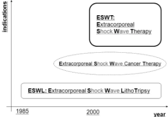
technique combining orthopeadics and lithotripsy [10], named ‘orthopeadic lithotripsy’, in short, ‘orthotripsy’ [1]. It gave birth to an offspring of ESWL, now known as Extracorporeal Shock Wave Therapy (ESWT) [11]. Figure 2 graphically summarizes the evolution of ESWL to ESWT and extent of their indication.
ESWT was approved for clinical use in plantar fasciitis by FDA in 2000 and since then it becomes rapidly accepted in clinics [12]. Figure 3 demonstrates schematically shock wave irradiation to the site
causing plantar fasciitis. Indications of ESWT cover shoulder, elbow, heel, non-union bones [13,14] and have been continuously widened to various areas including wound healing, obesity therapy and cardiology [15,16,17].
Although the obvious clinical success of ESWT, action mechanisms behind ESWT are not clearly understood, yet. Without doubt, the clinical efficacy of ESWT is closely associated with shock wave exposure and the clinical efficacy of ESWT may be optimized by controlling the acoustic output from ESWT devices. The acoustical aspects need to be clarified for investigating mechanisms through which therapeutic effects are obtained in ESWT. This article aims to review the acoustical aspects of ESWT and to discuss some critical issues towards optimization in shock wave exposure and in shock wave dosimetry.
II. Extracorporeal Shock Wave Therapy
ESWT is now regarded as an efficient alternative non-invasive procedure for orthopedic treatment on tendonitis, calcifications and pseudoarthrosis. ESWT may be positioned between former unsuccessful conservative therapy and surgery. The clinical role and significance of ESWT are displayed in Figure 4, based on the data obtained from 60,000 patients in Germany between 1997 and 1998 [1]. About 75 % of the patients treated with ESWT was reported to be free of complaints and improved. Compared to conventional surgical treatments, ESWT offers distinctive advantages such as out patient treatment, short treatment time, reduced risk compared to surgery, no general / partial anesthesia, no special post treatment and no scars [1,18].Indications of ESWT include calcific tendonitis of rotator cuff (shoulder calcification), lateral epicondylitis (tennis elbow) plantar fasciitis (heel spur), pseudoarthrosis (non-union fractures), dorsal heel spur, haglund’s exostosis, medial epicondylitis (Golf elbow), supraspinatus tendon syndrome, achillodynia,
Fig. 4. Clinical role and significance of ESWT based on the data obtained from 60,000 patients in Germany [1].
Fig. 5. Indications illustrated for a domestic (Korean) clinical ESWT system (HYDRON-EZ, HnT Medical, Republic of Korea).
patellar tendonitis (jumper’s knee), trochanteric insertional tendonitis [1,19]. Figure 5 shows an example of depicted indications with a domestic (Korean) clinical ESWT system (HYDRON-EZ, HnT Medical, Republic of Korea). ESWT has steadily expanded its applications to pain management, obesity treatment, wound healing and cardiological
applications. [1,20].
Action mechanisms of ESWT are not clearly revealed, yet, but they may include [1]: (1) structural damages where high energy shock waves break up the calcium deposits on the calcified tendon resulting in revascularization or neovascularization, and stimulate pseudoarthrosis fracture sites, resulting in osteogenic effects, (2) stimulation of metabolic reactions where mid or low energy shock waves may alter membrane permeability of cells, and (3) analgesic effects where hyperstimulation by mid or low energy shock waves to axons that trigger pain may produce analgesic effects.
III. Shock wave production
A shock wave generator is composed of pulse power supply, shock wave transducer and a device for focusing shock waves [21,22]. Figure 6 shows an equivalent circuit diagram for a shock wave generator excluding focusing devices [23,24].
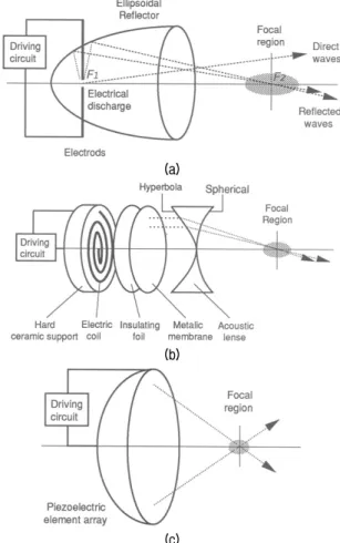
The shock wave transducer commonly employed in ESWT are divided into three essentially different types: electrohydraulic (EH), electromagnetic (EM) and piezoelectric (PE) type. Figure 7 displays the schematic of each type of the shock wave generator coupled with focusing device [25]. Note that there is a pneumatic method which has infrequently been used in ESWT. This type produces an acoustic impulse, being characteristically different in both spectral and temporal property from the above common 3 types. The acoustic impulse produced may not be classified as shock wave since it does not show a shock front. The clinical significance remains uncertain in the pneumatic type and the present article excludes this type.
The EH shock wave generation employs a pair of opposing metal electrodes connected in series with a driving circuit (Figure 7a). The electrodes are surrounded by a Faraday-like cage which electrically isolates electric discharge. The electrode gap is located at the first focus (F1) of a rotationally symmetrical
Fig. 6. An equivalent circuit diagram of a shock wave generator coupled with pulse power generator and shock wave transducer.
(a)
(b)
(c)
Fig. 7. Three different modes of the shock wave generation and focusing method used in clinical ESWT: (a) electrohydraulic (EH), (b) electromagnetic (EM) and (c) piezoelectric (PE) type.
ellipsoidal metal reflector and immersed in water. The capacitor of the driving circuit, charged to high voltages in ranges of 10 ~ 20 kV, is discharged through the water between the electrodes. The temperature of water near the electrodes rises very rapidly reaching several thousand K. The resulting heated gas, plasma, expands at a supersonic speed
before collapsing [26]. During the rapid expansion stage, the compressive part of the acoustic pulse is produced, and it is followed by a long tail of decaying pressure which goes negative. The secondary pulse is emitted during rebounding of the plasma bubble about 500 μs after voltage discharge and it is much weaker than the primary [27]. About 90 % of the energy of the pressure waves emitted from the electrode gap is reflected to the second focus (F2) of the ellipsoidal reflector, while the unfocused part remains spherically diverging.
As seen in Figure 7b, the EM shock wave transducer has a flat spirally wound coil fixed on a rigid support and an insulating foil placed to prevent electrical breakdown between the coil and a metallic membrane faced to water. When the capacitor is discharged, strong electric current pulse flows through the coil. The magnetic field in the metal membrane then changes and this induces an eddy current on the metal membrane. Two magnetic fields between the coil and the metal membrane influence each other and the metal membrane is repelled from the coil [28]. This movement of the membrane results in acoustic disturbances which set up plane waves [29]. These plane waves are focused by a bi-concave acoustic lens placed in front of the metal membrane. The field generated by the electromagnetic source is highly reproducible and stable [30,31]. Shot to shot variation in temporal peak positive pressure measured at the focus, for example, has been reported to be within 5 % [32].
The PE shock wave transducer consists of a number of piezoelectric elements mounted inside the surface of a partial spherical dish filled with water (Figure 7c). A high voltage is applied to all the piezoelectric elements simultaneously by discharging the capacitor, and the subsequent deformation of the elements results in acoustic pulses into the adjacent water. The pulses emitted from the piezoelectric elements are directed to the centre of the spherical dish and no additional focusing device is needed. The impedance of the electrical network and the time function of the drive voltage step are required to be
Fig. 8. A photograph of the cylindrical electromagnetic shock wave transducer [30].
Fig. 9. A typical shock waveform measured at the focus of a domestic electromagnetic shock wave generator (HnT Medical, Republic of Korea) [37].
matched to the electro-acoustical characteristics of piezoelectric elements, so that a small amplitude of tensile pressure of the pulse with few cycle oscillations can be obtained [33]. The wave energy released over the generator area is limited by the tolerance of piezoelectric material. In general this is much lower than the other types of shock wave sources, accordingly the piezoelectric element array is required to be large to obtain the same acoustic energy at the focus as the other types. The shot to shot variation has been observed highly stable, about 1 % in peak pressures.
The EH type was dominating in early stages in clinical applications of shock waves and was reported to yield good clinical outcomes. But it is inherently unstable in shock production and thus is difficult to precisely control shock wave exposure. In contrast, the PE type is highly reproducible in shock production but needs to be relatively large in its aperture size to produce a similar acoustic power to the other types. The EM type has its acoustical properties being between the other two types. Since the EM type had advantages in stability and efficiency in shock wave production over the other types. it rapidly replace the EH type. Notwithstanding the EH shock wave generator still serves as a gold standard in clinical efficiency. The EM type based on the flat coil (depicted in Figure 7b) was evolved to employ a cylindrical shape of solenoid coil [34]. This type has an advantage of being capable of not only producing a large shock wave energy with a
relatively small size of aperture but also housing ultrasonic imaging probe in its central hole [30]. Figure 8 show a photograph of such cylindrical shock wave transducer with a parabolic focusing reflector developed at our lab which is now taken to a domestic ESWT system ‘ShineWave’ (HnT Medical, Republic of Korea).
IV. Characteristic parameters of shock
wave field
Shock wave used in clinical ESWT is characterized by a large amplitude pulse lasting for ~ 10 us with the pulse repetition frequency of ~ 1 Hz [35,36]. It has a peak positive pressure rising up to 20 ~ 100 MPa within ~ 10 ns with a very broad frequency spectrum (10 kHz ~ 100 MHz) whose center frequency is in the range of 0.2 ~ 0.5 MHz [25,35]. The negative pressure downs to 10 ~ 50 % of the positive peak pressure. Figure 9 shows a typical pressure waveform of the shock wave which was measured at the focus of the electromagnetic shock wave generator (HnT Medical, Republic of Korea) using an optical hydrophone FOPH2000 (RP Acoustics, Germany). The waveform displayed was obtained by averaging 15 recordings at the same position pulse with the repetition frequency 0.2 Hz at the setting 5 [37,38]. The peak positive pressures (P+) and the peak negative pressures (P-) are marked in the figure.
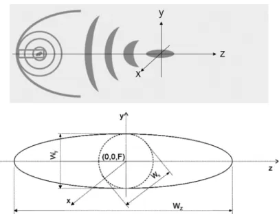
Fig. 10. Schematic of focusing (upper) and the focal geometry (lower) of the shock wave field produced by an electrohydraulic type shock wave generator used in ESWT. F: focus, Wx & Wy: focal width in x and y direction, respectively, Wz: focal depth.
The pressure distribution near and through the focus has an ellipsoidal sphere in shapes with its long axis in the direction of shock wave propagation. Figure 10 illustrates the focal geometry of the shock wave field produced by an EH type shock wave generator where F is the acoustic beam focus, Wz is the focal depth, Wx and Wy are the focal width in x and y direction, respectively. The parameters of Wz, Wx and Wy are often defined according to -6 dB criterion (IEC61846) or at a threshold pressure of 5 MPa (International Society of Musculoskeletal Shockwave Therapy - ISMST).
In addition to those shock wave parameters, energy flux density (efd) was often taken as an important parameter for dosimetry in ESWT [39]. The efd is the shock wave energy per unit area, flowing through an area perpendicular to the direction of propagation, which can be calculated by
(1)
where ρ is the density, c is the speed of sound, p(x,y,z,t) is the time history of the acoustic pressure pulse at a spatial position (x,y,z), T is the pressure pulse length. This is the same as the derived pulse
intensity integral (IEC61846), the time integral of the instantaneous intensity a particular point in a pressure pulse field over the pressure pulse waveform at the focus. The efd has units of Joule per metre squared (J/m2). Acoustic energy is calculated by the integral of the efd(x,y,z) over a cross sectional area in the x-y plane at z is near or at the focus. The efd cited in most literatures often indicates that at the focus (x=0,y=0,z=F) like the peak pressures P+ and P-.
V. Acoustic output of clinical ESWT systems
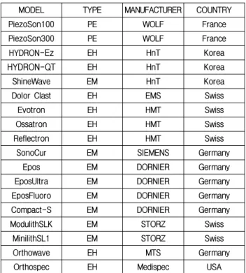
There are a number of commercial ESWT systems readily available from the market throughout the world including domestic models. Table 1 lists the models and their manufacturers of popular clinical ESWT systems.According to the data provided by International Society of Musculoskeletal Shockwave Therapy (ISMST), the ranges of the key acoustic parameters produced by the commercial ESWT devices are summarizes as:
∙Focal Positive Peak Pressure P+ (MPa)
Table 1. Popular clinical ESWT systems readily available from the market.
MODEL TYPE MANUFACTURER COUNTRY
PiezoSon100 PE WOLF France
PiezoSon300 PE WOLF France
HYDRON-Ez EH HnT Korea
HYDRON-QT EH HnT Korea
ShineWave EM HnT Korea
Dolor Clast EH EMS Swiss
Evotron EH HMT Swiss
Ossatron EH HMT Swiss
Reflectron EH HMT Swiss
SonoCur EM SIEMENS Germany
Epos EM DORNIER Germany
EposUltra EM DORNIER Germany
EposFluoro EM DORNIER Germany
Compact-S EM DORNIER Germany
ModulithSLK EM STORZ Swiss
MinilithSL1 EM STORZ Swiss
Orthowave EH MTS Germany
Orthospec EH Medispec USA
∙ Max: 25.6 (Sonocur) ~ 132.0 (Piezoson300)
∙ Focal Energy Flux Density (mJ/mm2)
Min: 0.03 (Epo-Fluore) ~ 0.14 (Piezoson300) Max: 0.15 (Reflectron) ~ 2.00 (Modulith)
∙ -6 dB focal size (Wx, Wy, Wz in mm) Wz: 4.2 (Piezoson100) ~ 103.0 (EposFluoro) Wx: 1.3 (Piezoson100) ~ 26.0 (Orthospec) Wy: 1.3 (Piezoson100) ~ 25.5 (Orthospec) It is shown that commercial ESWT devices produce extremely wide variety of acoustic outputs. For example, Piezoson300 has 132 MPa in focal P+ which is about 5 times larger than that from Sonocur. The maximum focal efd was 2.0 mJ/mm2 from Modulith and it is 13 times larger than that from Reflectron. The focal sizes among all the parameters most significantly differ from devices up to 25 times. Piezoson100 is 4.2 mm in Wz while Epos-Fluoro is 103 mm. It should be noted that data for focal P- are not available from ISMST. This would be because the parameter is difficult to measure using current technologies and also its clinical significance is unclear and in controversy. Measuring accurately shock wave field requires
a very expensive delicate broad band hydrophone not easily available as well as high levels of expertise [37]. Accordingly the spatial variations of shock waves parameters from current commercial devices are not readily available, even if they are similar to those from ESWL devices, about which considerable data were reported by some dedicated researchers [35,36]. The article presents preliminary data about the focal field measured on the 1st domestic ESWT system HYDRON-Ez (HnT Medical, Republic of Korea) which employs an EH shock wave generator. Figure 11 shows variations in the peak pressures (P+ and P-) along the three orthogonal directions of x, y and z axis through the focus. The data (means and standard deviations of error bars) were obtained from the shock wave forms measured repeating 5 times using a membrane hydrophone (HMB-0200, Onda, Seattle, USA). All measurements were carried out at the setting number of 3 of the shock wave generator, enabling the capacitor to charge upto about 30 % of the maximum voltage. Figure 11a displays the peak positive and negative pressures (P+, P-) along the beam (z) axis. The pressure at the focus (at z = 20 mm) reached ~ 20 MPa in P+, and was about -2 MPa in P-. The focal depth, Wz(-6 dB) was about 20 mm in P+, but was unrealistically small in P- [40].
The peak distributions cross the beam axis through the focus along x and y direction are respectively shown in Figure 11b and 11c. As seen in the figures, they are almost similar in either direction of x and y, representing the expected axial symmetry of the focal beam. Slight deviation from symmetry may be due to the electrode located near the ellipsoid reflector. The focal width, is the same in both direction of x and y, for instance, Wx(-6 dB) and Wy(-6 dB). The focal width was about 8 ~ 9 mm in P+, but about twice for P-. Those preliminary data presented here indicates that the acoustic properties for the domestic model (HYDRON-Ez, HnT Medical, Republic of Korea) were found to be within ranges of current EH type ESWT systems [40].
(a)
(b)
(c)
Fig. 11. Distributions in the peak positive (left panels) and negative (right panels) pressures of the shock waves generated by HYDRON-Ez (HnT Medical, Republic of Korea), measured along the 3 orthogonal directions (x, y and z axis) through the focus along (a) the beam (z) axis, (b) x axis and (c) y axis. (means and standard deviations of error bars were obtained from 5 repeated measurements using a membrane hydrophone (NTR System, Seattle, USA).
VI. Acoustic exposure and critical issues
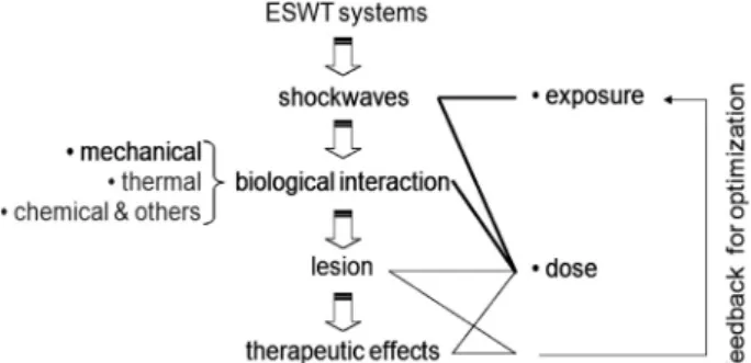
Process leading to therapeutic effects in ESWT is drawn in Figure 12. The clinical efficacy relies onshock wave acoustic exposure and the therapeutic outcome can be effectively predicted based on shock wave dose. The dose can be defined as a quantity of shock wave exposure closely related to biological effects. TI or MI in diagnostic ultrasound would be
Fig. 12. Process leading to therapeutic effects of ESWT and a control loop for optimization.
such parameters that combine ultrasonic irradiation with resulting biological responses. By far shock wave dose parameter has not yet been established while acoustic exposure in ESWT is specified in terms of various parameters including efd, total acoustic energy, shock wave number to administer, P+, P-, shock pulse repetition frequency and -6 dB (or 5 MPa) focal sizes. Establishing a unified dose quantity in medical ultrasound in general will be very difficult because ultrasonic radiation can not be quantified by a single parameter but has to be characterized with various parameters (pressure, frequency, waveform, mode) and also induces multiple biological effects including mechanical (cavitation), thermal, chemical interactions. Note that the biological interaction with shock waves is understood to be associated more with mechanical effects including cavitation [38,41,42,43,44], while high intensity focused ultrasound surgery uses thermal effects to ablate tumor.
Acoustic exposure in commercial ESWT systems can be controled by the following 5 factors: (1) nominal setting numbers (subject to an individual ESWT system, for instance, 1~10 for the domestic HnT HYDRON-Ez), (2) shock wave generation methods (EH, EM and PE), (3) focusing geometry (ellipsoidal, parabolic, spherical), (4) shock wave number administered (1,000 ~ 3,000) and (5) pulse repetition frequency (0.5 ~ 10 Hz). All the factors except the shock wave number to administer (the factor 1, 2, 3 and 5) may be unified to temporal & spatial properties of shock wave fields. As discussed in Section V,
there is a great deal of variety of the acoustic output from commercial ESWT systems. The reason for such a large variability may be due to lack of understanding on action mechanisms to shock waves on specific tissues. This prevents ESWT from quantifying shock wave dose as well as does not allow us to optimize shock wave exposure maximize required biological effects on a target tissue. Under the circumstances, the question ‘which ESWT system is better?’ can not be scientifically answered, even if every commercial model (has to) boasts its own outstanding clinical efficacy. Answering to the question will bring about controversy until optimal shock wave exposure conditions are disclosed.
For optimizing the shock wave exposure, we need to elucidate biological or therapeutic effects to shock wave exposure on a specific tissue. Systematic studies integrating in vitro, in vivo and clinical tests as well as acoustic characterization of ESWT devices are proposed to relate biological responses to shock wave exposure as drawn in Figure 13. The control (independent) parameters in Figure 13 are ‘s’ and ‘w’, representing the setting number of shock wave generators and the shock wave field, respectively. The parameter w will be further divided into such various parameters as efd, acoustic energy, shock wave number to administer, P+, P-, shock pulse repetition frequency and -6 dB (or 5 MPa) focal sizes, characterizing the temporal and spatial properties of shock wave. The parameter s is subject to an ESWT system unlike w. In practice, it is required to measure w(s) characterizing the acoustic output from each ESWT device. The dependent variables ‘c’, ‘a’ and ‘p’ stands for biological or clinical responses to shock wave in cells, animals and patients, respectively. The proposed studies are likely to yield cellular responses to shock wave (c(w)), in vivo animal tests to shock wave (a(w)), and clinical outcomes to shock wave (p(w)).
An example of p(w) is presented in Figure 14, which is clinical effects in relation to focal energy flux density. Scraps of information on p(s), clinical efficacy as a function of settings of ESWT devices
may be obtained during clinical treatments. Provided that shock wave exposure as a function of settings of ESWT systems w(s) is known, p(w) will be derived by combining p(s) and w(s). In fact, a number of research were carried out with clinical ESWT systems without knowing their acoustic outputs against settings, in order to observe c(s), a(s) and p(s) [13]. These results were subject to the ESWT devices and can not be generalized [12]. Ideas for exposure optimization and shock wave dose may be gained integrating appropriately biological tests on commercial systems (c(s), a(s) and p(s)) and acoustic characteristics of the systems (w(s)). While c(s), a(s) and p(s) are relatively easily available, w(s) is not readily available. This is because shock wave measurement needs a high level of expertise and an expensive broadband hydrophone and can be performed in very limited places. The w(s) often provided by manufacturers should be validated by an accredited third party institution.
VII. Closing remarks
ESWT is simply evolved from ESWL a revolutionary technique for treating kidney stones and, since it was approved by FDA for treating plantar fasciitis, it has rapidly accepted into clinical practice as an efficient alternative non-invasive procedure for chronic calcified tendonitis [1,45] and pseudoarthrosis. Its clinical applications have been expanded to various areas including enhanced bone & wound healing and therapy for ischemic heart diseases [46,47]. A number of research are underway to open new applications [48].
Despite clinical acceptance, mechanisms behind ESWT are not fully understood yet and optimum shock wave exposure conditions have not been established. These reflect an extremely wide variety of acoustic outputs from current commercial ESWT systems. The question, ‘which ESWT system is better?’ can not be answered until one can answer to ‘what is the optimal shock wave exposure for ESWT?’ Such
optimization requires considerable knowledge about biological responses as well as action mechanisms to shock wave exposure on a specific tissue. The knowledge will be foundation for establishing a proper shock wave dose parameter, quantifying the exposure condition closely associated with biological effects on tissues. Shock wave exposure is currently administered in terms of setting parameters such as nominal setting number, shock wave number, pulse repetition frequency, which is highly subject to ESWT devices. The shock wave dose parameter, if it is defined, can enable clinicians to prescribe shock wave exposure to patients more precisely and scientifically without being subject to an individual ESWT system. Future studies may therefore have to focus on shock wave dosimetry, so that clinical efficacy is optimized based on shock wave dose parameters, and safety is monitored in terms of dose quantity, leading to ESWT with dose based planning like typical radiotherapeutic process.
Acknowledgements
This work is supported by Technology Development Support Program Utilizing Hightech Equipments (S1067913) of the Small & Medium Business Administration, Republic of Korea, and in part by the Basic Science Research Program through the National Research Foundation of Korea funded by the Ministry of Education, Science and Technology (2010-0017329), Republic of Korea.
References
1. C. E. Bachmann, Gruber, G. W. Konermann, A. Arnold, G. M. Gruber, and F. Ueberle, “ESWT and Ultrasound Imaging of the Musculoskeletal System,” Steinkopff Verlag Darmstadt, Germany, 2001.
2. M. J. Choi, “Application of ultrasound in Medicine: Therapeutic ultrasound and ultrasound contrast agent,” Journal of the Korean Society for Noise & Vibration Engineering, vol. 10, no. 4, pp. 743-759, 2000.
ESWL,” Ultrasound in Medicine & Biology, vol. 27, pp. 683– 93, 2001.
4. C. G. Chaussy, W. Brendel, and E. Schmiedt, “ESWL: Past, Present, and future,” J. Endourol., vol. 2, no. 2, pp. 97-105, 1988. 5. H. Schulze, L. Hertle, J. Graff, P. J. Funke and T. Senge, “Combined
treatment of branched calculi by percutaneous nephrolithotomy and extracorporeal shock wave lithotripsy,” J. Urology, vol. 135, pp. 1138-1141, 1986
6. G. O. Oosterhof, G. A. H. J. Smitd, J. E. de Ruyter, J. A. Schalken, and F. M. J. Debruyne, “In vivo effects of high energy shock waves on urological tumors: an evaluation of treatment modalities,” J. Urology, vol. 144, pp. 785-789, 1990. 7. A. Spindler, A. Berman, E. Lucero and M. Braier, “High energy
extracorporeal shock wave treatment for chronic calcific tendinits of the shoulder,” J Rheumatol, vol. 25, pp. 1161-1163, 1998.
8. G. Haupt, “Use of extracorporeal shock waves in the treatment of pseudarthrosis, tendopathy and other orthopedic diseases,” J. Urol., 158, 4–11, 1997.
9. S. Heidersdorf, S. Lauber, H. J. Lauber, H. Hötzinger, J. Ludwig, U. Dreisilker, and R. Rödel, “Osteochondritis dissecans in Musculoskeletal Shockwave Therapy,” Greenwich Medical Ltd., pp. 255-261, 2000.
10. J. D. Rompe, P. Eysel, C. Hopf, O. Krishek, J. Vogel, R. Burger, J. Jage and J. Heine, “Extracorporeal shockwave therapy in orthopedics. Positive results in tennis elbow and tendinosis calcarea of the shoulder,” Fortschr Med, vol. 115, pp. 29-33, 1997.
11. J. A. Ogden, A. Toth-Kischkat, and R. Schultheiss, “Principles of shock wave therapy,” Clin. Orthop., vol. 387, pp. 8-17, 2001. 12. R. Alvarez, “Preliminary Results on the Safety and Efficacy of the
Ossatron for Treatment of Plantar Fasciitis,” Foot Ankle Int., vol. 23, pp. 197-203, 2002.
13. C. J. Wang, H. S. Chen, C. E. Chen and K. D. Yang, “Treatment of Nonunions of Long Bone Fractures With Shock Waves,” Clinical Orthopaedics & Related Research, vol. 387, pp. 95-101, 2001. 14. V. Valchanow and P. Michailow, “High energy shock waves in the
treatment of delayed and non-union fractures,” Int. Orthopaed, vol. 15, pp. 181–185, 1991.
15. T. A. Davis, A. Stojadinovic, K. Amare, M. Anam, S. Naik, G. E. Peoples, D. Tadaki, and E. A. Elster, “Extracorporeal shock wave therapy suppresses the acute early proinflammatory immune response to a severe cutaneous burn injury,” Int Wound J, vol. 6, pp. 11–21, 2009.
16. Y. R. Kuo, W. S. Wu, Y. L. Hsieh, F. S. Wang, C. T. Wang, Y. C. Chiang and C. J. Wang, “Extracorporeal shock wave enhanced extended skin flap tissue survival via increase of topical blood perfusion and associated with suppression of tissue proinflammation,” J Surg Res, vol. 143, pp. 385–392, 2007.
17. Y. Fukumoto, A. Ito, T. Uwatoku, T. Matoba, T. Kishi, H. Tanaka, A. Takeshita, et al, “Extracorporeal cardiac shock wave therapy ameliorates myocardial ischemia in patients with severe coronary artery disease,” Therapy and Prevention. Coron. Artery Dis., vol. 17, no. 1, pp. 63–70, 2006.
18. M. Maier, H. R. Durr, S. Kohler, D. Staupendahl, M. Pfahler, and H. J. Refior, “Analgesic effect of low energy extracorporeal shock waves in tendinosis calcarea, epicondylitis humeri radialis and plantar fasciitis,” Z Orthop Ihre Grenzgeb, vol. 138, pp. 34-38, 2000. 19. C. J. Wang, J. Y. Ko and H. S. Chen, “Treatment of calcifying
tendinitis of the shoulder with shock wave therapy,” Clin. Orthop.,
vol. 387, pp. 83-89, 2001.
20. A. Gutersohn, G. Caspari, and R. Erbel, “Autoangiogenesis Induced by Cardiac Shock Wave Therapy (CSWT) Increases Perfusion and Exercise Tolerance in Endstage CAD Patients with Refractory Angina,” Circ. J., vol. 69, no. s1, pp. 379, 2005.
21. P. V. Chitnis, “Characterization and comparative analysis of extracorporeal shock wave devices,” M.Sc. Thesis, Boston University, Boston MA, USA, 2000.
22. F. E. Prieto, A. M. Loske, and F. L. Yarger, “An underwater shock wave research device,” Review of Scientific Instruments, vol. 62, pp. 1849–1854, 1991.
23. S. C. Cho, “Optimization of a cylindrical electromagnetic shock wave transducer,” MSc Thesis, Jeju National University, Jeju, Republic of Korea, 2008.
24. D. E. Johnson, J. R. Johnson and J. L. Hilburn, “Electric Circuit Analysis, 2nd ed., Prentice-Hall, Inc., Englewodd Cliffs, 1992. 25. M. J. Choi, “Physical aspects of high amplitude pulsed ultrasound
used in lithotripsy,” PhD Thesis. University of Bath, England, 1992. 26. R. O. Cleveland, M. R. Bailey, N. Fineberg, B. Hartenbaum, J. A.
McAteer, and B. Sturtevant, “Design and characterization of a research electrohydraulic lithotripter patterned after the Dornier HM3,” Review of Scientific Instruments, vol. 71, pp. 2514–2524, 2000. 27. H. P. T. Hunter, B. Finlayson, R. J. Hirko, W. C. Voreck, R. Walker,
S. Walck, and M. E. Naser, “Measurement of shock wave pressures used for lithotripsy,” J. Urology, vol. 136, pp. 733-738, 1986. 28. C. T. A. Johnk, “Engineering Electromagnetic Fields and Waves,”
2nd ed. John Wiley & Sons, New York, USA, 1988.
29. W. Eisenmenger, “Experimental determination of shock front thickness from the acoustic spectrum of shock wave with shock pressure between 10 and 100 atm generated with electromagnetic means in liquids,” Acustica, vol. 14, pp. 184, 1964.
30. S. C. Cho, G. S. Kang, S. H. Sang, K. I. Lee, D. G. Paeng, and M. J. Choi, “Properties of the acoustic fields of a domestic electromagnetic extracorporeal shock wave therapy system,” Proceedings of the Acoustical Society of Korea. vol. 26, no. 2s, pp. 237-238, 2007.
31. W. Folberth, G. Köhler, A. Rohwedder and E. Matura, “Pressure distribution and energy flow in the focal region of two different electromagnetic shock wave sources,” J. Stone Disease, vol. 4, pp. 1–5, 1992.
32. H. Reichenberger and G. Naser, “Electromagnetic acoustic source for the extracorporeal generation of shock waves in lithotripsy,” Siemens Forschungs Und Entwicklungs Berichte, vol.15, pp. 187-194, 1986.
33. H. Reichenberger, “Lithotripter system,” Proc. of the IEEE, vol. 76, no. 9, pp. 1236-1246, 1988.
34. S. H. Lee, J. H. Lee, H. J. Lee, and M. J. Choi, “Electromagnetic and dynamic properties of an electromagnetic type shock wave source: numerical simulation,” Proc. of the Acoustical Society of Korea, vol. 20, no. 1s, pp. 917-920, 2001.
35. A. J. Coleman, M. J. Choi, and J. E. Saunders, “Theoretical predictions of the acoustic pressure generated by a shock wave lithotripter,” Ultrasound in Medicine & Biology, vol. 17, no. 3, pp. 245-255, 1991.
36. A. J. Coleman, and J. E. Saunders, “A survey of the acoustic output of commercial extracorporeal shock wave lithotripters,” Ultrasound in Medicine & Biology, vol. 15, pp. 213–220, 1989. 37. M. J. Choi, S. C. Cho, D. G. Paeng, K. I. Lee, and A. J. Coleman,
“Acoustic characterization of a domestic commercial shock wave therapy system for the treatment of chronic tendonitis using a
broadband optical hydrophone,” The 7th International Symposium of Therapeutic Ultrasound, Seoul, 12-15 June 2007.
38. M. J. Choi, S. C. Cho, G. S. Kang, D. G. Paeng, K. I. Lee, M. Hodnett, B. Zeqiri, and A. J. Coleman, “Quantification of acoustic cavitation produced by a clinical extracorporeal shock wave therapy system,” Modern Physics Letters B, vol. 22, no. 11, pp. 809-814, 2008.
39. A. M. Loske, “The role of energy density and acoustic cavitation in shock wave lithotripsy,” Ultrasonics, vol. 50, pp. 300–305, 2010. 40. M. J. Choi, S. C. Cho, and A. J. Coleman A J, “Characterization
of a commercial shockwave therapy system developed for the treatment of chronic tendonitis,” UKTUIG Meeting, IRC, London, 28 Feb. 2006.
41. A. J. Coleman, M. J. Choi, and J. E. Saunders, “Detection of acoustic emission from cavitation in tissue during clinical extracorporeal lithotripsy,” Ultrasound in Medicine & Biology, vol. 22, no. 8, pp. 1079-1087, 1996.
42. M. Delius, “Medical applications and bioeffects of extracorporeal shock waves,” Shock waves, vol. 4, pp. 55–58, 1994.
43. O. A. Sapozhnikov, A. D. Maxwell, B. MacConaghy and M. R. Bailey, “A mechanistic analysis of stone fracture in lithotripsy,” Journal of the Acoustical Society of America, vol. 121, pp. 1190– 202, 2007.
44. B. R. Matlaga, J. A. McAteer, B. A. Connors, R. K. Handa, A. P. Evan, J. C. Williams, J. E. Lingeman, and L. R. Willis, “Potential for cavitation-mediated tissue damage in shock wave lithotripsy,” The Journal of Endourology, vol. 22, pp. 121–26, 2008.
45. M. Loew, W. Daecke, D. Kusnierczak, M. Rahmanzadeh, and V. Ewerbeck, “Shock-wave therapy is effective for chronic calcifying tendinitis of the shoulder,” J Bone Joint Surg Br, vol. 81, pp. 863- 867, 1999.
46. H. G. Neuland, A. Lang, and P. Kraemer, “Heat shock proteins, extracorporeal shockwaves and wound healing process,” Presentation no. 40; 10th Int. Congress of the ISMST, 6~9 June 6th 2007, Toronto, Canada, 2007.
47. Y. Ito, K. Ito, T. Shiroto, R. Tsuburaya , G. J. Yi, M. Takeda, Y. Fukumoto, S. Yasuda, and H. Shimokawa, “Cardiac shock wave therapy ameliorates left ventricular remodeling after myocardial ischemia-reperfusion injury in pigs in vivo,” Coron. Artery Dis., vol. 21, pp. 304-311, 2010.
48. A. M. Loske, J. Gutierrez, E. D. Grazia and F. Ferrnandez, “Out-of-focus shockwaves: a new tissue-protecting therapy?,” Archivo Italiano di Urologia e Andrologia, vol. 76, pp. 159–162, 2004.
【Profile】
∙ Min Joo ChoiThe Journal of the Acoustical Society of Korea, vol.27, no.2E, 2008. Present: Professor, Department of Medicine, School of Medicine (& Interdisciplinary Graduate Program of Biomedical Engineering), Jeju National University, Korea, and Honorary Lecturer, School of Medicine, King’s College London & Medical Physics Department, Guy’s & St Thomas’ NHS Foundation Trust, London, UK.
∙ Sung Chan Cho
B.Sc in Electrical Engineering from Jeju National University, Korea, 2002~2004.
M.Sc in Biomedical Engineering from Jeju National University, Korea, 2007~2009.
Ph.D course in Biomedical Engineering from Jeju National University, Korea, 2009~present.
Senior Researcher, R&D Institute, COMED Medical Co., Ltd, Korea, 2000~2004.
CEO, HNT Medical Co.,Ltd, Korea, 2004~2007. CTO, HNT Medical Co.,Ltd, Korea, 2007~present.
∙ Dong-Guk Paeng
The Journal of the Acoustical Society of Korea, vol.28, no.2E, 2009. Present: Associate Professor, Department of Oceanic Information & System Engineering (and Interdisciplinary Graduate Program of Biomedical Engineering), Jeju National University, Korea.
∙ Kang IL Lee
The Journal of the Acoustical Society of Korea, vol.29, no.2E, 2010. Present: Assistant Professor, Department of Physics, Gangwon National University, Korea.

![Fig. 9. A typical shock waveform measured at the focus of a domestic electromagnetic shock wave generator (HnT Medical, Republic of Korea) [37].](https://thumb-ap.123doks.com/thumbv2/123dokinfo/4909249.40563/5.892.100.419.893.1094/typical-waveform-measured-domestic-electromagnetic-generator-medical-republic.webp)