Journal of International Conference on Electrical Machines and Systems vol. 3, no. 4, pp. 428~432, 2014 428
Design, Development and Analysis of Embedded Systems for
Condition Monitoring of Rotating Machines using FFT Algorithm
Sanket Dessai*, and Zakiyaunnissa Alias Naziya Naaz*
Abstract –
Rotating machines are an integral part of large electrical power machinery in most of the industries. Any degradation or outages in the rotating electric machinery can result in significant losses in productivity. It is critical to monitor the equipment for any degradation’s so that it can serve as an early warning for adequate maintenance activities and repair. Prior research and field studies have indicated that the rotating machines have a particular type of signal structure during the initial start-up transient. A machine performance can be studied based on the effect of degradation in signal parameters. In this paper a data-acquisition system and the FFT algorithm has been design and model using the MATLAB and Simulink. The implementation had been carried out on the TMS320 DSP Processor and various testing and verification of the machine performance had been carried out. The results show good agreement with expected results for both simulated and real-time data. The real-time data from AC water pumps which have rotating motors built-in were collected and analysed. The FFT algorithm provides frequency response and based on this frequency response performance of the machine had been measured.The FFT algorithm provides only approximation about the machine performances.Keywords:
Final Rotating Machine FFT Algorithm, Machine Performance TMS320DM642 DSP Processor1. Introduction
Rotating machines cover a wide range of critical facilities and provide the backbone of numerous industries, from gas turbines used in the production of electricity to turbo-machinery utilized to generate power in the aerospace industry. It is vital that these machines run safely over time and under different operational conditions, to ensure continuous productivity and prevent any catastrophic failure, which would lead to extremely expensive repairs and may also endanger the lives of the operating personnel. Condition monitoring is the process of monitoring a parameter of condition in machinery, such that a major change is indicative of developing failure. It is a main component of predictive maintenance. The use of conditional monitoring allows maintenance to be scheduled, or other actions to be taken to avoid the consequences of failure, before the failure occurs.
The basic steps for the condition monitoring depends on the understanding the electric, magnetic and mechanical behaviour of the rotating machine. When a machine is started for the activity to perform during this process a
certain level of vibration transient signals are occurred in the machine. Vibration measurement provides a very efficient way of monitoring the dynamics conditions of a machine such as unbalance misalignment, mechanical looseness, structural resonance, soft foundation and shaft bow.
The demand for low noise machinery has become an increasingly important issue in our society. Whenever a rotating machine is turned on a direct step signal is not achieved, a transient signals are obtained. These signals in many areas can be modelled as a super-position of several damped sinusoids. Hence rotating machines generates a signals composed of sinusoids equi-spaced in frequency. Some examples are power line surges when appliances/loads are turned ON or OFF, DOA- RF/Antennas and mechanical vibration transients during start up (motors, generators etc.). The spectrum of such signals is useful in detecting faults. A traditional Fourier-based spectrum estimation method is used in this method to do the signal analysis.Spectrum analysis is the process of determining the frequency domain representation of a time domain signal and most commonly employs the Fourier transform. A spectrum analyzer can measure the noise, frequency of response, signal-to-noise ratio, and distortion inherent spectrum.
* Dept. of Computer Engineering, MSRSAS, India. ([email protected] and [email protected])
Fast Fourier Transform (FFT) which is a special case of the generalized Discrete Fourier Transform and converts the signal from its time domain representation to its equivalent frequency domain representation. However, frequency analysis (sometimes called Spectral Analysis) is only one aspect of interpreting the information contained in a vibration signal. Frequency analysis tends to be most useful on machines that employ rolling element bearings and whose main failure modes tend to be the degradation of those bearings, which typically exhibit an increase in characteristic frequencies associated with the bearing geometries and constructions.
A rotating part in a machine generates exponential sinusoids, vibration and noise which lead to imperfections in the functioning of the electrical embedded systems.
Fourier series: An infinite series whose terms are
constants multiplied by sine and cosine functions and that can, if uniformly convergent, approximate a wide variety of functions.
Periodic-Continuous: Examples for periodic continuous
Fourier series is sine waves, square waves, and any waveform that repeats itself at a regular pattern from negative to positive infinity. This version is called the Fourier series.
Periodic-Discrete: These are discrete signals that repeat
themselves in a periodic fashion from negative to positive infinity. This class of Fourier Transform is sometimes called the Discrete Fourier Series.
Fourier transform: converts a time-domain signal, to
frequency domain. Fourier transform of a signal determines the frequencies present in a signal. Just like a prism which shows different frequencies of light present in a light source, Fourier transforms helps in untangling the tangled waveforms.
Aperiodic-Continuous: Examples for aperiodic continuous is decaying exponentials and the Gaussian curve. These signals extend to both positive and negative infinity without repeating in a periodic pattern. The Fourier Transform for this type of signal is simply called the Fourier Transform.
Aperiodic-Discrete: These signals are only defined at
discrete points between positive and negative infinity, and do not repeat themselves in a periodic fashion. This type of Fourier transform is called the Discrete Time Fourier Transform.
Discrete Fourier transform: A DFT is a Fourier that
converts discrete data from a time wave into a frequency spectrum.
... (1)
F (n) is the amplitude at the frequency n and N is the number of discrete samples.
Fast Fourier transform: The Fast Fourier Transform
does not refer to a new or different type of Fourier transform. It refers to a very efficient algorithm for computing the DFT. An FFT is an algorithm that speeds up the calculation of a DFT.
1.1 DSP Processor
Fig. 1. Block Diagram for the Condition Monitoring of the
Rotating Machine
To have a better implementation of the FFT Algorithm a DSP processor is more suitable then the conventional processor. As in this embedded system an extensive FFT algorithm need to be computed based on the rotating speed of the electric machine. In this system DM642 EVM is a low-cost standalone development platform that enables users to evaluate and develop applications for the TI TMS320DM64x DSP family. Evaluators can create software to execute on board or expand the system in a variety of ways. The EVM also serves as a hardware reference design for the TMS320DM642 DSP. Schematics, logic equations, and application notes are available to ease hardware development and reduce time to market.
The heart of the DM642 is the C64x CPU which includes special instructions to accelerate the performance. Also, the RISC-like instruction set and extensive use of pipelining in C64x, allow many instructions to be scheduled and executed in parallel. Parallelism is the key to extremely high performance needed for video and imaging applications. A high performance two-level cache design allows the CPU to operate at the maximum rate. The two-level cache lowers development time by automating off-chip to on-off-chip data transfers. A high performance EDMA controller feeds the CPU through flexible high-bandwidth bus architecture. TMS320DM642 DSP is operating at the 225MHz with a 16Mbytes of synchronous DRAM and 512 Kbytes of non-volatile flash memory.
2. Design and Implementation
Fig. 2. Implementation of FFT for the Condition
Monitoring of the Rotating Machine
Fig. 3. Hardware prototype of the FFT Implementation for
Condition Monitoring of the Rotating Machine This section describes about the design of the embedded system and its implementation for the condition monitoring of the rotating machine. Fig 1 shows the block diagram of Condition Monitoring of Rotating Machine. The transient signal is captured from the rotating machines (motor or generator) which conditions need to be monitored, this captured signal is modelled as exponentially damped sinusoidal and it is analogous in nature. Hence using analog to digital converter the analog transient signal is converted to digital signal. The digital signal is subjected to signal processing algorithm like FFT. Based on the FFT spectrum the output of the machine is carefully analysed and compared based on the damping and frequencies as shown in Fig 2.A Hardware setup for the condition monitoring is shown in the Fig 3.
3. Verification and Testing
To ensure that the baseline MATLAB and SIMULINK code is functioning correctly, generate a known input signal with known frequency. The output of MATLAB and SIMULINK blocks are validated to show equivalence with the input signals. The actual sampled real signals captured via data acquisition systems are then tested and validated. The different test cases had been simulated to determine the
performance of the rotating machine, the following testing of the machine has been shown in the Table 1, 2 and 3.
Table 1. Showing the Test Case: Test_1
Test Case ID Test_1
Description Running machine 1 signal in the scenario.
Justification The signal frequency should be determined.
Steps 1. Start the Simulink simulator 2. Select machine 1 Signal 3 Run the simulation
Test Setup A signal from the machine 1. Input Running machine 1 signal for the built
scenario.
Output The frequency of machine 1 signal is determined
Status Simulation successful.
Comment The machine 1 signal frequency obtained from simulator is same as that of MATLAB and the obtained frequency captured from the machine.
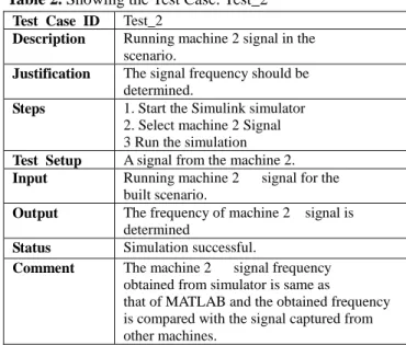
Table 2. Showing the Test Case: Test_2
Test Case ID Test_2
Description Running machine 2 signal in the scenario.
Justification The signal frequency should be determined.
Steps 1. Start the Simulink simulator 2. Select machine 2 Signal 3 Run the simulation
Test Setup A signal from the machine 2. Input Running machine 2 signal for the
built scenario.
Output The frequency of machine 2 signal is determined
Status Simulation successful.
Comment The machine 2 signal frequency obtained from simulator is same as that of MATLAB and the obtained frequency is compared with the signal captured from other machines.
Table 3. Showing the Test Case: Test_3
Test Case ID Test_3
Description Running a degraded machine signal in the scenario.
Justification The signal frequency should be determined.
Steps 1. Start the Simulink simulator 2. Select Signal
3 Run the simulation
Test Setup A degraded signal from the machine. Input Running the signal for the built
scenario.
Output The frequency of signal is determined Status Simulation successful.
Comment The degraded machine signal frequency obtained from simulator is same as that of MATLAB
4. Results and Discussions
In this section stage-wise signals are obtained from different machine and its results bas been discussed. Fig. 4 shows the different signals which were measured from four different machines (three healthy water pump motors and one which is degraded water pump) but all the four machines had same specification rating and these signals are used to determine the machine conditions using FFT.
Fig. 5 and Table. 4 show output of FFT obtained in MATLAB for synthetic data. The synthetic data of FFT contains both frequency and damping of the signals. But from FFT only frequency of the signals is estimated. The main reason for developing the synthetic data was to verify the developed algorithm.
Fig. 4. Signal Obtained From Different Machine of the
Rotating Machine
Fig. 5. Signal Obtained From Different Machine of the
Rotating Machine
Table 4. Showing the Different Machine Signal and its
Frequency
Signals Frequency (Hz)
Signal 1 50
Signal 2 100
Signal 3 200
Table 5. Showing the Frequency of the Different Machine
and its Performance
Type Of Machine Frequency (Hz)
Good Machine 1 49.6646
Good Machine 2 48.9621
Good Machine 3 49.6969
Degraded Machine 49.786
Fig. 6. Signal Obtained From Different Machine of the
Rotating Machine
Fig. 6 and Table. 5 shows an FFT output which is obtained for real time data. From the above plot it is clear that the frequency of all the four machines is of approximately 50Hz hence FFT based analysis is tedious to conclude about the machine performances and not very accurate.
Fig. 7. Signal Obtained From Different Machine of the
Rotating Machine
Fig. 7 shows an FFT output which is obtained for real time data on the target board i.e. TMS320DM642. The output is obtained by simulating all the four different signals which were captured from different machines. But from FFT only the frequency of the signal is determined. The output obtained from software model of MATLAB is same as that of the real-time hardware implementation using the TMS320DM642.
5. Conclusion
Embedded condition monitoring of rotating machines is carried out using FFT algorithm which is signal processing techniques. Verification of the algorithms through real field data captured by data acquisition systems for monitoring the health of rotating machines is performed.
An FFT algorithm helps in determining the frequency analysis of the rotating machine. Just from the frequency analysis only the approximation can be determined. In future new algorithm can be used to determine the performance of the machine.
References
[1] J. Fan, W. Zhongqiu and Z. Zhencai, “Fault Severity Estimation of Rotating Machinery Based on Residual Signals,” Advances in Mechinical Engineering, Hindawi Publishing Corporation, July 2012.
[2] F.Badour, M Sunar, L.Cheded, “Vibration Analysis of Rotating Machinery Using Time-Frequency Analysis and Wavelet Techniques,” King Fahd University of Petroleum and Minerals, Dhahran 31261,Saudi Arabia,3rd Edition, August 2008.
[3] Z.P. Tomasz and D Krzysztof, “Frequency and Damping Estimation Methods” AGH University of Science and Technology, Department of Tele communications, August 2011, pp.32-48
[4] L. Cheded and M. Sunar, “Non-stationary Vibration Signal Analysis of rotating machinery via Time-Frequency and Wavelet techniques,” International Conference on Information Sciences Signal Processing and their Applications(ISSPA),IEEE Explore, May 2010,pp.21-24. [5] B.Hocine, B.Salah and B.S.Mohamed, “Application of
Wavelet Transform for Fault Diagnosis in Rotating Machinery,” International Journal of machine Learning and computing, Vol 2,No 1.February 2012,pp.82-87
[6] A.A. Lakis, “Rotating Machinery Fault Diagnosis Using Time-Frequency Methods,” 7th WSEAS International Conference on Electric Power Systems, High Voltages, Electric Machines, Venice, Italy, November 21-23,2007,pp.139-144.
[7] D.Subhra, M.F.Quereshi, A.Reddy, D.Chandrakar, D.Pansari, “A Wavelet Based Multiresolution analysis for Real-Time Condition Monitoring of AC Machine Using Vibration Analysis,” International Journal of Scienctific and Engineering Research Vol2, Issue 10,Octomber 2011, pp.1-5. [8] N. Milind, “Bearing Fault Analysis Using frequency Analysis
and Wavelet Analysis,” International Journal of Innovation, Management and technology,Vol.4,No1,February 2013,pp.90-92
[9] C.Sujatha and C.Chandran, “On Various specialized Vibration techniques for detection of bearing faults”, Department of Applied Mechanics, Indian Institute of technology, Madras 600 036,India
[10] R.Yan and R.Gao, “Impact of wavlet basis on Vibrational analysis for rolling bearing defect diagnosis,” School of Instrument Science and Engineering Southest University, Nanjing 210096, China.
[11] Q.Shuren, “Sampling Technique in Wavelet Analysis of Vibrating Signals of Rotating Machinery,” Chongqing University,China,40044
[12] D.F.Shi, F.Tsung, P.J.Unsworth, “Adaptive Time-Frequency Decomposition for transient Vibrational Monitoring Machinery” Mechanical Systems and Signal Processing, Elsevier Ltd,2003,pp.127-141
[13] A. Muszynska, Vibrational diagnostics of rotating machinery malfunctions, International Journal of Rotating Machinery 1 (1995) pp.237–266.
[14] D.E. Newland, Wavelet analysis of vibration part2: wavelet maps, ASME Transactions, Journal of Vibration and Acoustics 116 (1994) pp.417–425.
[15] G. Genta, C. Delprete, Acceleration through critical speeds of an anistropic, non-linear, torsionally stiff rotor with many degrees of freedom, Journal of Sound and Vibration 180 (1995) 369–386.
Sanket Dessai received B.Sc, and MSc in
Physics from Goa University, India and MSc[Engg] degree in Real-Time Embedded Systems from Coventry University, U.K His research interests are Real-Time Embedded Systems, SoC design, MEMS and NEMS Engineering, Nanotechnology, Solid State Physics and Photonics
Zakiyunnissa received B.E from Vishve
technological University, India and MSc in Real-Time Embedded Systems from Coventry University, U.K. Her research interests are Real-Time Embedded Systems and Electro-mechanics