The Design of Component Cooling Water System in the Conventional Facilities of PEFP
G. P. Jeon,a J. Y. Kim,a Y. S. Cho,a B. H. Choi,a S. T. Yoo,ba PEFP, KAERI, P.O. Box 105 Deok-Jin Dong, Yu-Seong Gu, Dae-Jeon 305-353, Korea b KOPEC, inc., 360-9 Mabuk-ri, Guseong-eup, Yongin-si, Gyeongi-do, 449-713, Korea
1. Introduction
The Component Cooling Water System (CCW) provides cooling water to remove the heat generated from the equipments in the Conventional Facilities of Proton Engineering Frontier Project. It transmits it to the Tower Cooling Water System (TW) using the component cooling water pumps and component cooling water heat exchangers.
In this paper, we made the design of component cooling water system of accelerator, beam application research building and ion beam application building in the Conventional Facilities of Proton Engineering Frontier Project . To keep the cooling water temperature uniformly, the CCW System is comprised of 9 separate and independent subsystems : 7 for the accelerator tunnel and klystron area, 1 for the beam application research area, and 1 for the ion beam application building.
2. CCW system configuration 2.1 System Design Criteria
1) The cooling water system should be sized to adequately dissipate the heat to the TW System from the following equipments :
- Accelerator tunnel components(Accelerator/RFQ) - Klystrons
- Beam application research area components - Ion beam application building components
2) The cooling water system comprises nine separate and independent subsystems ; seven for the accelerator tunnel and klystron area, one for the beam application research area, and one for the ion beam application building. The subsystem for each couple of an accelerator(or RFQ) and klystron provide a continuous cooling water supply at a maximum temperature of 37oC, for the beam application research area
components and ion beam application bldg at a maximum temperature of 35oC. Each subsystem consist
of two 100-percent capacity pumps, two 100-percent heat exchangers, a surge tank, and distribution piping, valves and instrumentation.
3) Each subsystem should be initially filled with demineralized water from the demineralized water system and circulated through the deionizer and deoxidizer unit until the desired quality of water is reached. Seven separate and independent subsystems for the accelerator tunnel and klystron area have one deionizer and deoxidizer unit for common use and each subsystems for the beam application research area and
the ion beam application building has one deionizer and deoxidizer unit.
The quality of water is maintained during operation by bypassing 10% of the flow the deionizer and deoxidizer unit. Strainers should be installed in the forward of cooling water pumps and backward of the heat exchangers.
4) The heat exchanger is a plate type.
5) The cooling water system should be designed to include pump redundancy. The standby pump will start automatically if the system pressure decreases below a preset value
6) Materials of heat exchanger and pipe are austenitic stainless steel (304 SUS).
7) One surge tank is installed to be used common for seven separate and independent subsystems for the accelerator tunnel and klystron area and each one surge tank for the subsystems for the beam application research area and the ion beam application building. The surge tank which is replenished with demineralized water from the demineralized. Water Makeup System is pressurized with nitrogen to prevent oxygen from entering the system and be connected to the cooling pumps' suction. The surge tank provides a reservoir to compensate leakage from the system, the expansion and contraction of the cooling fluid with changes in system temperature, a constant suction head source of the cooling water pumps. Component Cooling Water system requirements is shown in Table 1.
Table 1. Component Cooling Water System Requirements
Bldg Component Heat Load (105kcal/hr -unit) Flow rate (m3/hr -unit) Inlet Design Temp. (°C) Allowabl e Max. Outlet Temp. (°C) RFQ 4.32 180 37 40 DTL1 5.2 180 37 40 DTL2 10.4 360 37 40 Accelerat or Tunnel DTL3 10.4 360 37 40 Klystron
Gallery Klystrons 121.0(total) 1260 37 L/E
BARA TL/BL 3.42(total) 35 M/E
BARA TL/BL 17.1(total) 35 IBAB ImplantersIon 1.02(total) 35
Transactions of the Korean Nuclear Society Autumn Meeting Busan, Korea, October 27-28, 2005
2.2 System configuration
The cooling water system includes the pipe, valves, and equipment within the boundaries from the surge tank to the inlet of piping supplying cooling water to each component, and from the cooling water outlet piping of the component to the cooling water pump. 2.2.1. Accelerator Tunnel & Klystron gallery
To observe the design criteria, heat exchanger with plate type is applied to CW system. With pump redundancy, two cooling water pumps of 100% capacity should be installed to its system. Capacity of deionizer and deoxidizer is calculated to the 10% of total flow rate(2560m3/hr). Cooling water collected
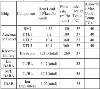
from each equipments is stored in surge tank. It keeps clean by DW makeup system pressuered with nitrogen gas to prevent oxigen. It is sent to each component through cooling water pump for removing heat and returned to surge tank repeatedly. CCW P&ID of Accelerator Tunnel and Klystron gallery for RFQ + Klystron#1(a) and for DTL 1 + Klystron#2(b) is shown in Fig. 1.
a)
b)
Fig. 1 CCW P&ID of Accelerator Tunnel and Klystron gallery : a) for RFQ + Klystron#1 b) for
DTL 1 + Klystron#2
2.2.2. Beam Application Research Area
Total heat load of BARA is 2,052,000 kcal/hr and flow rate/heat load of BARA is the same as that of Accelerator and klystron at 0.0155%. Therefore, total flow rate is calculated to 318 m3/hr. The capacity of
each component is estimated to 350 m3/hr : 110% of
total flow rate due to 10% increasing flow rate entering deionizer and deoxidizer.
2.2.3. Ion Beam Application Building
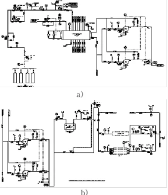
The CCW system of Ion beam application building is similar with that of Accelerator and Klystrons except for capacity of each component. This system is also applied to two 100% water pumps with pump redundancy. The 10 % of total flow rate circulated through deionizer and deoxidizer to supply demineralized water. CCW P&ID of Ion Beam Application Building is shown in fig. 2
Fig. 2 CCW P&ID of Ion Beam Application Building 3. Conclusion
We made the design of component cooling water system of Accelerator tunnel & Klystron gallery, Beam application research area and Ion beam application building in the conventional facilities of PEFP. To keep the cooling water temperature uniformly, the CCW System is comprised of 9 separate and independent subsystems : seven for the accelerator tunnel and klystron area, one for the beam application research area, and one for the ion beam application building.
In the phase Ⅱ, started to July 2005, we are making the detail design of cooling water system in the conventional facilities of PEFP.
ACKNOWLEDGEMENT
This work is a part of the “Proton Engineering Frontier Project” which is sponsored by the Ministry of Science and Technology of Korea under “21C Frontier R&D Program”.
REFERENCES
[1] B. H. Choi, "Status of the Proton Engineering Frontier Project", proceeding of PAC, 2005
[2] KAERI, PEFP, " Operation manual of cooling water system equipments for proton accelerator ", 2003