1. INTRODUCTION
Active lighting [1-6] techniques have been used extensively in vision applications for depth measurement and 3-D surface reconstruction. Although measuring the distance and orien-tation of a planar surface using nonstructured lighting [1] is possible, many studies in this area focused on structured lighting. Multiple striped lights [2,3] and rectangular grid of lines [4] are examples of light patterns. The spatial resolution is usually low using multiple or grid of lines. There are also potential ambiguities in matching stripe segments resulting from object surfaces at different depth [7]. An alternative is to use a single light stripe and have it swept over the scene [5][6] by rotating the light projector. One possible drawback of this method is that the image of projected light could be blurred due to its movement. This deteriorates the measurement precision. Another issue arises from the accuracy of the light projection angle. These systems make use of the principle of triangulation to compute depth. For depth much larger than the distance between the camera and the light projector, a small angular error on light projection could cause a significant measurement error. A very precise and reliable measurement of the projection angle can be difficult while the light projector is being rotated.
In this paper, a setup with the use of a rotational mirror is presented. This system is composed of a single camera, a laser light projector and a rotating mirror. The striped laser light is projected toward the rotational axis of the mirror, and reflected to the surface to be measured. The camera detects the striped light on object surfaces through the same mirror. There
are 5 parameters involved to compute depth in this system. The error sensitivities with respect to these parameters are analyzed and the calibration techniques for major parameters are proposed in this paper.
Calibration of the depth measurement system with a laser pointer, a camera
and a plain mirror
Hyongsuk Kim*, Chun-Shin Lin
**, Seongchan Gim*, and Heesung Chae
**** Division
of Electronics and Information Engineering,Chonbuk National Univ., Republic of Korea, [email protected], [email protected] **Department of Electrical and Computer Engineering
University of Missouri-Columbia, Columbia, MO 65211 USA
***Electronic and Telecommunication Research Institute, Republic of Korea, [email protected]
Abstract: Characteristic analysis of the depth measurement system with a laser, a camera and a rotating mirror has been done and the parameter calibration technique for it has been proposed. In the proposed depth measurement system, the laser beam is reflected to the object by the rotating mirror and again the position of the laser beam is observed through the same mirror by the camera. The depth of the object pointed by the laser beam is computed depending on the pixel position on the CCD. There involved several number of internal and external parameters such as inter-pixel distance, focal length, position and orientation of the system components in the depth measurement error. In this paper, it is shown through the error sensitivity analysis of the parameters that the most important parameters in the sense of error sources are the angle of the laser beam and the inter pixel distance. The calibration techniques to minimize the effect of such major parameters are proposed.
Keywords: depth measurement, mono camera, rotating mirror, laser, calibration, sensitivity
2. The New Depth Measurement System with
Striped Lighting
The new depth measurement system has the single vertical laser light stripe projected to the rotating mirror, and reflected to the scene. The image formed by the same mirror is acquired by the CCD camera. Figure 1 shows the picture of the developed measurement device and the triangulation geometry for the single point projection. Without losing the generality, we focus on the image formation of a single light point. Figure 1(b) shows that the light is reflected by the mirror and projected to an object surface. Note that the mirror can be rotated.
Let the angle between the vertical line and the light source be ζ, and the angle of the mirror from the horizontal axis be θ. Also, let the distance between the camera axis and the rotating axis of the mirror be δo, the distance between the focal point of
the camera and the horizontal axis be dm, and the focal
distance of the camera be f.
The laser light is reflected onto the object at point T with the mirrored image at T’. When the mirror angle is θ, ∠SOT, which is the angle between the projected light and the reflected light, equals 2(θ-ζ) and the angle ∠TOM equals (90o-θ+ζ). Since T’ is the mirrored image of T, we have ∠T’OM = ∠TOM = 90o
Consequently, ∠SOT’ = 2(θ -ζ) + (90o-θ+ζ) + (90o-θ+ζ) = 180o. This shows that T’ will always be on the line along the laser beam, at a distance R from the point O. This character-ristic indicates that if the depth of the scanned points during one frame of capturing period is not changed, the image of laser light will remain sharp. Figure 2 illustrates the effect; the projected light point (near the center of the image) is clear while the background gets blurred due to mirror rotation. In image processing, the blurred background actually makes the light point (or stripe) stand out and easy to detect. Note that the part of clear picture at the right is from the scene outside of the mirror.
(a) The measurement system
(b) Triangulation geometry for a single point projection Fig. 1. Depth measurement with light projection and mirror
reflection
To derive equations for projection in 3-dimensional space, let’s use the cylindrical coordinate system with the mirror axis as the Z-axis. Assume that the light point T with coordinates
coordinates of image plan. Figure 1(b) shows the projection of a point on x-y plane. In this figure, px is the distance from P to the camera optical axis. Using the property of similar triangles, one obtains
'
:
T:
xp
f
=
δ
D
,
whereD
=
d
m+
d
T' . ' '(
)
(1)
or x m T Tp d
+
d
=
f
δ
T ' = cos , ' ' d R T O lT(2)
Note that ζ δ =δ − and lT'=Rsinζ(
cos )
(
sin ).
x m Op d
R
f
R
. Thusζ
δ
ζ
+
=
−
(3)
Solving the above equation for R gives
.
sin
cos
O x m xf
p d
R
f
p
δ
ζ
ζ
−
=
+
:
:
Z(4)
The angle for the observed point T is φ, which is defined as the angle measured clockwise from the vertical axis to the line OT. This angle is determined by the laser light direction and the mirror angle asφ = 2(θ-ζ) + ζ= 2θ - ζ.
(5)
For the value Z, the triangular similarity will givep
f
=
Z
D
. '(
)
Z m Tp d
d
fZ
(6)
or+
=
'/
/
(7)
Dividing (7) by (2), one obtainsZ x T
p
p
=
Z
δ
=
Z
/(
δ
O−
R
sin ).
ζ
(8)
Solving the above equation for Z gives(
sin )
.
z O xp
R
Z
p
δ
−
ζ
=
(9)
As a summary, R, φ, and Z can be computed by.
sin
cos
O x m xf
p d
R
f
p
δ
ζ
ζ
−
=
+
(4)
φ = 2θ - ζ.
(5)
and,(
sin )
.
Z O xp
R
Z
p
δ
−
ζ
=
(9)
Note that the mirror angle is not involved in equation (4) for depth computation. Only the fixed angle ζ is included and needs to be carefully calibrated. Conceptually, one canthe position of T’, which is the intersection of lines SO and PC (see Figure 1(b)); an error arises when either of those two lines is inaccurately determined. In this setup, the error from inaccurate SO can be minimized by calibrating the angle ζ. Note that for a setup with its laser projector rotated, a measurement error of the projection angle is harder to prevent; so is the depth error. The error from inaccurate PC is caused by inaccurate position of P. Since P is the pixel position of the light point, a sharper image tends to provide a more precise and reliable result. The characteristic of sharp image illustrated in Figure 2 helps minimize the error from this factor.
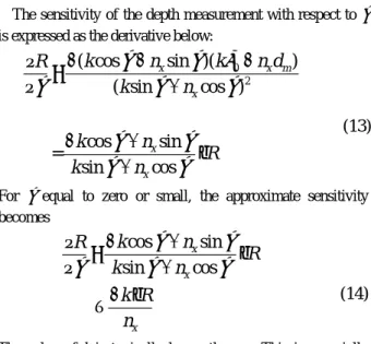
3.1 Sensitivity of the depth measurement with respect to ζ The sensitivity of the depth measurement with respect to ζ is expressed as the derivative below:
0 2
( cos
sin )(
)
( sin
cos )
cos
sin
=
sin
cos
x x m x x xk
n
k
n d
R
k
n
k
n
R
k
n
ζ
ζ
δ
ζ
ζ
ζ
ζ
ζ
ζ
ζ
−
−
−
∂
=
∂
+
−
+
⋅
+
(13)
For ζ equal to zero or small, the approximate sensitivity becomes
cos
sin
sin
cos
x x x
k
n
R
R
k
n
k R
n
ζ
ζ
ζ
ζ
ζ
−
+
∂
=
⋅
∂
+
− ⋅
≈
Projected light(14)
The value of k is typically larger than nx. This is especially
true when ζ is small and R is large (nx is small in this case). A
careful calibration of ζ is important for better precision at a longer distance.
Fig. 2. Laser light point (near the image center) remains sharp while the background is blurred due to mirror rotation
3.2 Sensitivity of the depth measurement with respect to k
3. Error Sensitivities
Similar to the case for ζ, the sensitivity to k is the derivative below:
In this section, the sensitivities of the depth measurement to parameters are derived. Let the integer nx be the pixel number
corresponding to px, which is the distance from the center of
image plane to P and δcell be the inter-cell distance on the CCD
sensor. Then px can be expressed as
2
( sin
cos )
(
)sin
( sin
cos )
sin
=
( sin
cos )
O x O x m x O xk
n
k
n d
R
k
k
n
R
k
n
δ
ζ
ζ
δ
ζ
ζ
ζ
δ
ζ
ζ
ζ
+
+
−
∂
=
∂
+
+
⋅
+
(15)
x cell xp
=
δ
n
(10)
Plugging (10) into (4) gives
When R is large value, (15) is approximated into
sin
cos
sin
cos
O cell x m cell x O x m cell x cellf
n d
R
f
n
f
n d
f
n
δ
δ
ζ δ
ζ
δ
δ
ζ
ζ
δ
−
=
+
−
=
+
sin
sin
xcos
R
R
k
k
n
ζ
ζ
ζ
∂
≅
⋅
∂
+
(16)
(11)
At the longer distance, the inaccurate selection of k will make large effect to the depth measurement error.
3.3 Sensitivity of the depth measurement with respect to nx
Similar to the case for k, the sensitivity to nx is the
derivative below: Replacing by k in (11) results in cell
f
δ
2( sin cos ) (cos )( ) ( sin cos ) cos = sin cos m x O x m x x m x d k n k n d R n k n d R k n
ζ
ζ
ζ
δ
ζ
ζ
ζ
ζ
ζ
− + − − ∂ = ∂ + − − ⋅ +sin
cos
O x m xk
n d
R
k
n
δ
ζ
ζ
−
=
+
(12)
(17)
Depth can be computed using equation (12) after the calibrated values of k and ζ have been obtained.
When ζ is small and R is large value, (17) is approximated into
cos
sin
cos
x xR
R
n
k
n
ζ
ζ
ζ
∂
≅
−
⋅
∂
+
(18)
Since ζ is usually small (i.e. less than
20
o), inaccurate measurement of the pixel position nx will make large effect tothe depth measurement error at long distance.
3.4 Sensitivities of the depth measurement with respect to δo and dm
Derivative of (4) with respect to δo gives
sin
cos
O xR
k
k
n
δ
ζ
ζ
∂
=
∂
+
(19)
Also, the derivative of (4) with respect to dm is
sin
cos
x m xn
R
d
k
ζ
n
ζ
−
∂
=
∂
+
(20)
Comparing the sensitivities of parameters, the sensitivities with respect to ζ, k and nx are proportional to R, while other
two do not. At the places of larger depths, inaccurate parameters of ζ, k and nx are expected to cause large error.
Therefore, these three parameters will make major effects to the measurement accuracy at long distance.
4. Calibration and Depth Computation
Sensitivity analysis at the previous section gives an idea that incorrect parameters of ζ, nx and k are more important thanothers. Since the nx is obtained from the laser image, the
parameter which needs to be calibrated is ζ and k. 4.1 Calibration of the internal parameter
cell
f
k
δ
=
The camera and the projector can be set up in parallel, i.e., with ζ = 0. This is achieved by adjusting the laser light source orientation so that the distance between the laser beam and the camera optical axis at a long distance (e.g., longer than 5 meters) equals δo. Upon having ζ set to 0, experiments can be
performed to obtain nx’s for different known ranges of R. The
collected pairs of R and nx can be plugged into (12) to obtain
the estimated values of parameter k; the average of these estimated values is used. This parameter needs to be calibrated only once.
4.2 Calibration of the external parameter ζ
For a system with unknown ζ, equation (12) can be used for calibration. One can set up the system to measure a known distance R. The value nx can be obtained from image. Values
of δo and dm are known and k has been calibrated. As a result,
value of depth is sensitive to the error of angle ζ, recalibration is recommended if the angle is possibly changed.
5. Experimental Results
In this section, experimental results are reported. A CCD camera (with 512×480 8-bit pixels) has been used in this study. The distances dm and δo were set to 15cm and 8cm,
respectively.
5.1 Calibration of k and ζ
The method described in Section 3 has been used to deter-mine the constant k. The average value of k evaluated at different distances with ζ set to 0o is 1377.56. For depth measurement experiments, ζ was set approximately to 4o. It was difficult to have ζ equal exactly to 4o. The precise value had to be obtained from calibration. The system was set up at a distance of 500cm from an upright planar surface. The value of nx for the projected light point was obtained. The actual ζ obtained through the calibration using (12) was 3.869o. Perfor-mance was evaluated for objects at different distances. Figure 3 shows the results for calculations with ζ = 3.869o and ζ = 4o compared with the real depth. Observing the Figure 3, we see that the calibration improves the measurement accuracy significantly.
Fig. 3. Results with and without having ζ calibrated.
6. Conclusions
A new depth measurement system that consists of a single camera, a laser light stripe projector and a rotating mirror has been investigated. There are 5 parameters involved to compute depth in this system. The sensitivity analysis shows that the ζ, k and nx are proportional to depth, which cause big depth
the major parameters are is ζ and k. The calibration techniques for is ζ and k are proposed in this paper. Simulation results show that the depth measurement results after the calibration are improved significantly than that before the calibration.
REFERENCES
[1] T. Tsukiyama, “Measuring the distance and orientation of a planar surface using nonstructured lighting - 3D measurement system for indoor mobile robots,” IEEE Tr. on Instrumentation and Measurement, vol. 45, no. 5, Oct. 1996.
[2] V. Srinivasan and R. Lumia, “A pseudo-interferometric laser range finder for robot applications,” IEEE Tr. on Robotics and Automation, vol. 5, no. 1, Feb. 1989. [3] M. Baba and T. Konishi, “Range imaging system with
multiplexed structured light by direct space encoding,” Proceedings of the 16th IEEE Instrumentation and Measurement Technology Conference, vol. 3, pp. 1437-1442, May 24-26, 1999.
[4] 4. P. M. Will and K. S. Pennington, “Grid coding: A preprocessing technique for robot and machine vision,” Artificial Intelligence, vol. 2, pp. 319-329, 1971. [5] 5. Y. Shirai and M. Suwa, “Recognition of polyhedrons
with a rangefinder,” in Proc. 2nd Int. Joint Conf. on Artificial Intelligence, pp.80-87, 1971.
[6] T. C. Strand, “Optical three-dimensional sensing for machine vision,” Optical Engineering, vol. 24, no.1, pp. 33-40, 1985.
[7] 7. R. Jain, R. Kasturi and B. G. Schunck, Machine Vision, McGraw-Hill Inc., 1995.