ICCAS2005 June 2-5, KINTEX, Gyeonggi-Do, Korea
Load Flow Calculation and Short Circuit Fault Transients in AC Electrified Railways
Seyed Hossein Hosseini*, and Farhad Shahnia**
*
Azarbaijan Regional Electric Company, Tabriz, Iran (Tel : +98-914-3134864; E-mail: [email protected])**Electrical and Computer Engineering Faculty, University of Tabriz, Tabriz, Iran
(Tel : +98-411-3393711; E-mail: [email protected])
Abstract: A load flow and short circuit fault simulation of AC electrified railway distribution systems is presented with DIgSILENT PowerFactory software. Load flow of electrified railways distribution system with concerning multi train lines and dynamic characteristics
of train load is studied for different time laps. The dynamic characteristics of train load in starting and braking conditions with different starting and stopping times and its moving positions makes the load flow complicated so there is a great need in studying the effects of electrified railways on load flow. Short circuit fault transients is also studied and simulated for both power system or traction distribution system and their effects on the operation of the train sets is investigated.
Keywords: AC Electrified railway, power distribution system, load flow, dynamic behavior, short circuit fault.
1. INTRODUCTION
The AC Electrified railways play an important role for public or mass transportation because of high efficiency, heavy ridership and fast transportation. To serve such a mass public transportation, the reliability of the whole power network is significant for the full performance of the railway system.
An electrified railway line resembles a typical power distribution system but the major difference is the changes in the positions of the trains called as the frequently moving loads. To solve the power consumption of the trains operation on the track, it is also necessary to investigate the dynamic load behavior of the train along the route. The dynamic behavior of the train loads mostly includes starting and stopping time intervals near the stations. Power demand of the traction substations vary over a wide range and a load may even become a power source when regenerative braking is allowed. Other factors such as train speed, traffic and service schedule and track layout have also great influence on the power demand of the electrified railway system.
The electrical power system feeding the railway should be designed in such a way that the voltages at the train sets are in the admissible range and the conductor currents and transformer powers are smaller than their rated values. The over design problems of the railway power system during the planning stage should be solved through load flow analysis which can lead to appropriate selection of the ratings of the transformers and feeder cables and enhancing the operation efficiency of the power system. The power substations have to be designed so that sufficient capacity can be provided for the normal operation and the scheme of load transfer can be implemented for the emergency condition when one of the substations is outaged. It is necessary to find the substation loading according to the ridership and operation timetable of the traction system [1,2].
The design of the electrical supply system of AC electrified railways lines mostly involves the selection of single 25 kV overhead contact system being fed through transformers or 50 kV being fed through +25/-25 kV autotransformers depending on different railway applications. The design of the catenary system and the location and sizing of the substations including transformers or autotransformers in AC traction substations
should be designed in such a way that the train voltages would be in the admissible range and the conductor currents and transformer ratings are smaller than their rated values, which can be studied and investigated through load flow analysis.
In this paper, a power distribution system including a railway traction system is simulated with DIgSILENT PowerFactory software. The dynamic characteristics of the train load such as starting, conventional and regenerative braking with different time intervals is simulated. The traction line is a multi train line, which the changes in the positions of the trains is also simulated at a specific time interval. The traction system is fed through some substations with transformer. Short circuit fault presence in power distribution network or traction distribution system is also simulated for considering its effects on both of the systems and the performance of traction system under faulty conditions. Meanwhile the voltage, current, active and reactive power dispatch on the whole system is measured in healthy and faulty conditions.
2. ELECTRICAL POWER SUPPLY SYSTEM
Several alternatives are used for designing the electrical scheme of the power distribution system for electrified railways [3]. Medium 15/25 kV, 60/50 Hz AC systems are usually used for medium power demands of 4-6 MW loads. High voltage 50 or 2x25 kV, 60/50 Hz system is appropriate for systems with higher power demand of 8-20 MW. Also, low frequency systems such as medium voltage 25 kV or 2x12.5 kV, 25 Hz is good for 4-8 MW load. Medium voltage 15 kV, 162/3 Hz is capable of feeding medium power levels. Lower frequency helps in reducing the cost, and the lower voltage help in reducing civil clearances.The commuter trains serving suburban areas, usually travel at top speed of up to 125 mph are fed from 15/25 kV catenary system feeding 3-4 MW. The traction substations are fed from 69, 115 or 220 kV systems. Since the stations are 5-10 miles apart, they do not need frequent stopping.
The high speed trains run at higher speeds up to 330 mph and may have more carriages; therefore, the power demand is higher. It is expected that more and more of high speed trains will be in operation in the near future. These systems are usually fed
through +25/-25 kV autotransformers. The power to the traction substation is supplied from the high voltage systems at 275 or 400 kV, which provides added reliability to the traction system.
The freight trains have much higher power demands, running slower than 80 mph but use much higher tractive power. The train sets for freight trains run on the same electrified railway tracks as the commuter or high speed trains do. The power needs are between 4 to 10 MW considering that higher power demands require very strong utility networks, traction substation and catenaries.
The traction substations are connected in parallel so that the power source of each traction substation can be switched from one traction substation to the other in the case of emergency outage of the related traction substation, resulting in increasing the reliability of the traction power distribution system [4,5]. This is especially useful when a fault is occurred in the line feeders or the traction substations, therefore an intelligent protection system can lead to feeding the rest of the system and preventing the outages on the whole part of the traction system.
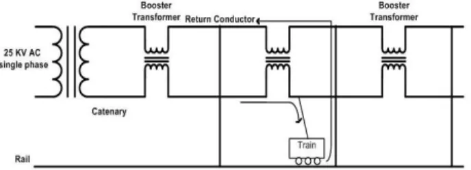
Single line diagram of power distribution system for AC electrified railway systems being fed through transformers and autotransformers is shown respectively in Figures 1 and 2. The transformers in Fig. 1 are single phase transformers which are feed through 3 phase power network but the secondary side and the overhead contact system is single phase. In addition, there are some booster transformers along the track between two respective traction substations for reducing the voltage drop along the track.
Fig. 1. Single line diagram of power distribution system for AC electrified railway systems with transformers.
Fig. 2. Single line diagram of power distribution system for AC electrified railway systems with autotransformers.
3. DYNAMIC TRAIN LOAD
For studying the load flow analysis of the traction power distribution systems, the power consumption of the train operation is necessary to be investigated and the dynamical behavior of the traction system loads along the route to be studied. Fig. 3 shows the typical speed profile of a train set between two stations. When the train starts from the first station, it operates in constant acceleration mode, shown in region I. As the speed reaches 22 km/hour, the operation mode is changed to
constant power, shown in region II. When the speed is above 37 km/hour, the train set is operated with the constant slip where the traction effort is inversely proportional to the square of the train speed, shown in region III. After the speed reaches the cruising speed, the train operates with coasting mode without applying any input propulsion power, shown in region IV. When the train approaches the next station, the electric regeneration braking is applied by operating the induction motors as induction generators so that the kinetic energy of the train set can be converted into electricity to achieve the energy conservation, shown in region V. For each operation mode, the power demand of the train set can be solved based on the acceleration and various types of train resistance.
Fig. 3. Speed characteristics of the train sets with time and place
variations.
The track layout has also a great effect on the dynamic load behavior of the traction systems. The route gradient and curvatures of the traction system, the distance between the adjacent stations and the headway time of the trains for different traffic and service schedules can differ the power demand of the traction systems greatly. The power demand of the train sets of a sample railway from the first station to the last one is shown in Fig. 4.
Fig. 4. Power demand characteristics of the train sets form the first station to the last.
4. LOAD FLOW AND FAULT CALCULATIONS
For performing power load flow analysis of the power distribution system of AC electrified railways, input train information, route gradient and curvature, data of the AC network, operation timetable, and the ridership of the traction system should be studied and analyzed for determining the accurate data of the power consumption of the train sets. Then, the power demand of the train performance according to the train speed, position and motion equation should be analyzed. At first, the power demand at the secondary side of the traction transformers should be done, then, the load flow analysis should be studied for the power network for each snapshot.Several papers have been previously presented about studying the load flow analysis of the electrified railway systems each using a self-created program packages through programming in C++ or other programming softwares [6-8]. In this paper, power system dedicated DIgSILENT PowerFactory software is used for power distribution system analysis of an AC electrified railway. The required programming for the dynamic behavior and the timetable of the train positions and starting and stopping periods are done through Dynamic Programming Language
(DPL) commands of the software based on FORTRAN.
Power load flow analysis of the software can be conducted using Raphson current iteration, classic Newton-Raphson and linear equation methods for the unbalanced power system feeding the traction substations. The software is also capable of studying the fault calculations and transients in the AC distribution system feeding the traction system and the traction system itself according to IEC, VDE and ANSI standards. It is possible to define any type of fault at any location such as the traction substations, train overhead contact system or the AC network feeding the traction substations using this software. Therefore, the stability and the reliability of the traction system can be investigated.
Studying the load flow analysis results during design period, accurate ratings of electrical equipment can be achieved and tested through simulation cases. It is also necessary to study power dispatch in the system under faulty conditions. For increasing the reliability of the traction electrical system, it is necessary to design the structure of the power distribution system in a way that it would be able to still be fed from other feeders when a disconnection occurs in a feeder. For that reason, the electrical distribution system as shown in Figures 1 and 2 is designed to be able to feed all of the traction substations without any problems such as overloading.
5. SIMULATION RESULTS
In this paper, an AC electrified railway distribution system is simulated with DIgSILENT PowerFactory software. The simulated system represents a 25 kV, 50 Hz railway electrified system consisting of 5 traction posts each with two single phase transformers, one for feeding the uptrack and the other for downtrack line. A schematic of the simulated study case is shown in Fig. 5. Because of using the educational version of the software with limits on the number of buses, no booster transformers between the traction substations are applied in this simulation.
Fig. 5. Schematic of the power distribution system for an AC electrified railway with DIgSILENT PowerFactory software.
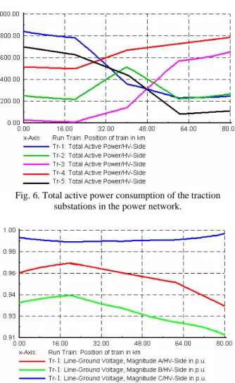
A dynamic program has been applied for the power consumption of the train sets being fed through every traction substation; therefore, the active power consumption of the traction substations is shown in Fig. 6. Also the magnitude of the phase voltage of a traction substation in the study case is shown in Fig. 7, where the same graph for the other traction substations has almost the same characteristics with little difference in magnitudes.
Fig. 6. Total active power consumption of the traction substations in the power network.
Fig. 7. Magnitude of line-ground voltage for a traction post. Faults in the AC electrified railway are divided into two categories. The first is the faults in the power network feeding the traction substations that depending on the fault type and duration can cause poor performance of the traction system. Three phase faults in the transmission lines feeding the traction substations have the worst effect resulting in the traction transformers to be outaged. However, considering a single phase or two phase faults, lower power can be fed to the traction substations and the rest power demand can be gained from adjacent traction substations, therefore the trains along the track would not suffer unless the high tractive force is needed by the trains. In Figures 8 and 9 the phase voltage and current and also the active power waveforms of a traction substation during a single phase short circuit fault in the transmission line feeding that traction substation are shown.
Fig. 8. Phase voltage and current of a traction substation at the presence of a fault in the feeding line of the traction substation.
Fig. 9. Active power variations of a traction substation at the presence of a fault in the feeding line of the traction substation.
The second and worst type of the faults is the short circuit fault in the overhead contact system of the trains. Considering that the overhead contact systems of the trains are single phase, short circuit fault appearance can cause great troubles for the train sets along that track. Such faults can result in the stopping of the trains along the track or the power equipment can be damaged severely. The phase current and voltage and the active power waveforms of a traction substation with a short circuit fault on the overhead contact system connected to that substation are shown in Figures 10 and 11.
Fig. 10. Phase voltage and current of a traction substation at the presence of a fault in the overhead contact system of the trains.
Fig. 11. Active power variations of a traction substation at the presence of a fault in the overhead contact system of the trains.
6. CONCLUSION
Load flow and short circuit fault calculations and transient simulations of the power distribution system of an AC electrified railway were presented in this paper. The simulation was conducted with DIgSILENT PowerFactory software. The load flow of the traction system was studied with considering the dynamic characteristics of the train sets at starting and baking times and the moving characteristic of the train sets using the DPL commands of the software. Short circuit fault transients were also studied for both power system or traction distribution system and their effects on the operation of the train sets were investigated.
REFFERENCES
[1] T.K. Ho, Y.L. Chi, J. Wang, K.K. Leung, "Load flow in electrified railway", IEEE 2nd Int. Conf. on Power Electronics, Machines and Drives, Vol. 2, Pages:498-503,
April 2004.
[2] C.S. Chen, H.J. Chaung, J.L. Chen, "Analysis and dynamic load behavior for electrified mass rapid transit systems",
IEEE 34th Int. Conf. Industry Applications, Vol. 2, pp.
992-997, October 1999.
[3] B. Bhargava, “Railway electrification systems and configurations”, IEEE Power Engineering Society Summer
Meeting, Vol. 1, pp. 445-450, July 1999.
[4] S. Sagareli, "Traction power systems reliability concepts",
Proc. of ASME/IEEE Joint Rail Conf., pp. 35-39, 2004.
[5] I. Zamora, E. Fernandez, E. Torres, A.J. Mazon, "Influence of faults in electric railway systems", IEEE 2nd Int. Conf. on Power Electronics, Machines and Drives, Vol. 2, pp.
504-509, April 2004.
[6] I. Dzafic, M. Glavic, S. Tesnjak, "An object oriented graphical package for power system simulation and analysis", IEEE 12th Mediterranean Int. Conf. on Electrotechnical, Vol. 3, pp. 835-839, Croatia, May 2004.
[7] T.K. Ho, J. Wang, K.K. Leung, C.T. Tse, L.K. Siu, "Probabilistic load flow calculation for AC traction supplies with AT feeding", IEE 6th Int. Conf. on Advances in Power System Control, Operation and Management, pp.
530-534, 2003.
[8] E. Pilo, L. Rouco, A. Fernandez, A. Hernandez-Velilla, "A simulation tool for the design of the electrical supply system of high speed railway lines", IEEE Power
Engineering Society Summer Meeting, Vol. 2, pp.
1053-1058, July 2000.