저작자표시-비영리-변경금지 2.0 대한민국 이용자는 아래의 조건을 따르는 경우에 한하여 자유롭게 l 이 저작물을 복제, 배포, 전송, 전시, 공연 및 방송할 수 있습니다. 다음과 같은 조건을 따라야 합니다: l 귀하는, 이 저작물의 재이용이나 배포의 경우, 이 저작물에 적용된 이용허락조건 을 명확하게 나타내어야 합니다. l 저작권자로부터 별도의 허가를 받으면 이러한 조건들은 적용되지 않습니다. 저작권법에 따른 이용자의 권리는 위의 내용에 의하여 영향을 받지 않습니다. 이것은 이용허락규약(Legal Code)을 이해하기 쉽게 요약한 것입니다. Disclaimer 저작자표시. 귀하는 원저작자를 표시하여야 합니다. 비영리. 귀하는 이 저작물을 영리 목적으로 이용할 수 없습니다. 변경금지. 귀하는 이 저작물을 개작, 변형 또는 가공할 수 없습니다.
A THESIS
FOR THE DEGREE OF MASTER OF SCIENCE
Development of Film-assisted Honey Bee Egg Collection System
(FECS) and Its Application to Honey Bee Genome Editing.
필름교환식 꿀벌 알 수집 시스템(FECS)의 개발과
꿀벌 유전체 편집에 대한 응용
By
Jaeho Lee
Department of Agricultural Biotechnology Seoul National University
A THESIS
FOR THE DEGREE OF MASTER OF SCIENCE
Development of Film-assisted Honey Bee Egg Collection System
(FECS) and Its Application to Honey Bee Genome Editing.
필름교환식 꿀벌 알 수집 시스템(FECS)의 개발과
꿀벌 유전체 편집에 대한 응용
By
Jaeho Lee
Department of Agricultural Biotechnology Seoul National University
Development of Film-assisted Honey Bee Egg Collection System
(FECS) and Its Application to Honey Bee Genome Editing
필름교환식 꿀벌 알 수집 시스템(FECS)의 개발과 꿀벌 유전체편집에 대한 응용
UNDER THE DIRECTION OF ADVISER SI HYEOCK LEE SUBMITTED TO THE FACULTY OF THE GRADUATE SCHOOL OF
SEOUL NATIONAL UNIVERSITY By
Jaeho Lee
DEPARTMENT OF AGRICULTURAL BIOTECHNOLOGY SEOUL NATIONAL UNIVERSITY
February 2019
APRROVED AS A QUALIFIED THESIS OF JAEHO LEE
FOR THE DEGREE OF MASTER OF SCIENCE BY THE COMMITTEE MEMBERS
CHAIRMAN Seunghwan Lee VICE CHAIRMAN Si Hyeock Lee
Development of Film-assisted Honey Bee Egg Collection System
(FECS) and Its Application to Honey Bee Genome Editing
Major in Entomology
Department of Agricultural Biotechnology, Seoul National University
Jaeho Lee
Abstract
Despite the huge potential of genome editing in honey bee research and breeding program, only a few successful cases of honey bee genome editing have been reported so far. With an aim of improving conventional protocol, I developed film-assisted honey bee egg collection system (FECS), which provides streamlined protocol in egg collection and microinjection procedure as well as potential applicability to other researches that require massive collection of high quality honey bee eggs. By employing FECS in honey bee genome editing to generate spinosad-resistant honey bee, I could generate mutant honey bees with their nicotinic acetylcholine receptor alpha 6 subunit (nAChR α6) knocked down
of successful honey bee genome editing using Cas9 ribonucleoprotein(RNP) instead of Cas9 mRNA. Although there were problems in assessing spinosad resistance with a limited number of mutant drones, I proved that haploid honey bees without functional nAChR α6 gene can develop into adult drones, of which various phenotypes, including behavioral characteristics and spinosad resistance, can be further analyzed.
Key words: Honey bee, Apis mellifera, Egg, Embryo, Microinjection, CRISPR,
Genome Editing, Knock-out, Spinosad, Resistance, Nicotinic Acetylcholine Receptor, Alpha 6, nAChR
CONTENTS
ABSTRACT... 1
LIST OF TABLES ... 8
LIST OF FIGURES... 9
CHAPTER 1. Development of Film-assisted Honey Bee Egg Collection System (FECS)... 1
Abstract ... 2
1. Introduction... 3
2. Materials and methods... 6
2.1. Source of honey bees ...6
2.2. Design, 3D printing and post processing of FECS components ...6
2.3. Use of plug-based system ...7
2.4. Comparison of collection efficiency and hatching rate ...9
2.5. Statistical analysis ...10
3. Results...12
3.1. Specification of FECS components...12
3.2. Feature of FECS...29
3.3. Comnparison of collection efficiency and hatching rate ...18
4. Discussion...20
Appendix: User Guide of FECS...20
Part1. 3d printing of FECS comb box and queen excluder ...23
Part2. Silicone coating of the comb box...29
CHAPTER 2.
Knockout of Nicotinic Acetylcholine Receptor α6 Subunit (nAChR α6) in the Western Honey Bee Apis mellifera - The Application of FECS to Genome
Editing...39
Abstract ...40
1. Introduction...41
2. Materials and methods...44
2.1. Source of Honey bee and egg collectioin ...44
2.2. DAPI (4′,6-diamidino-2-phenylindole) staining and fluorescent imaging ...44
2.3. Design, synthesis, and purificatno of single-guide RNA (sgRNA)...45
2.4. Design of single-stranded oligo DNA (ssODN)...48
2.5. Cas9 RNP assembly and In-vitro cleavage assay...49
2.6. Microinjection, in vitro rearing and grafting...50
2.7. Maintenance of mosaic queens and F1 drones...51
2.8. Bioassay...52
2.8. Sequencing of F1 drones ...52
3. Results...53
3.1. Florescne imaging of early embryos ...53
3.2. In-vitro cleavage asssay...56
3.3. Microinjection, grafting, and maintenance ...57
3.4. Sequencing of F1 drones ...59
3.5. Bioassay and phenotype observation...60
4. Discussion...63
LITERATURE CITED ...68
LIST OF TABLES
CHAPTER 2.
Knockout of Nicotinic Acetylcholine Receptor a6 Subunit (nAChR a6) in the
Western Honey Bee, Apis mellifera - The Application of FECS to Genome Editing
Table 1. Primers used in this study...48 Table 2. Injection conditions and results from following procedures. The number
of hatching embryos, grafted embryos, emerged queens and queens with offspring is also noted in the table ...58
Table 3. Injection condition of the queens and sequencing result of each queen.
Two out of three queens (66.7%) had genome edited offsprings ...60
LIST OF FIGURES
CHAPTER 1.
Development of Film-assisted Honey Bee Egg Collection System (FECS)
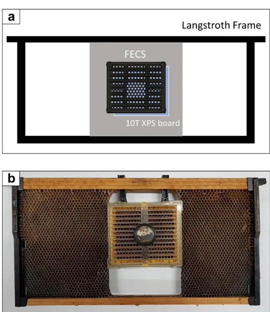
Figure 1. Diagram and picture of FECS and Royal queen rearing system used for
yield comparison test a FECS installed in a plastic frame housing. b Royal queen rearing comb box installed in a Langstroth deep frame.. ... 8
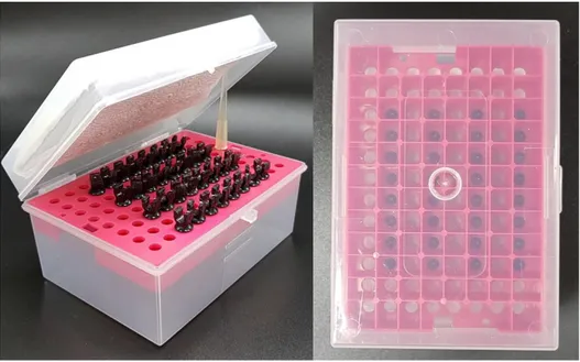
Figure 2. Plugs aligned on a micropipette tip box. Boxes were stored at incubator
upside down. Cardboard covered with paper towels were used to fill the gap between the lid and plugs. ...11
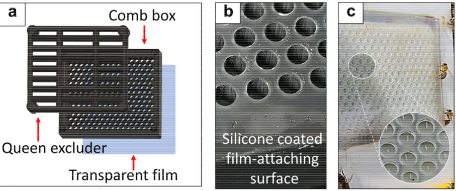
Figure 3. Overview of FECS. a Transparent film is attached to the back side of
the comb box. b Silicone rubber coating offers tight and easy attachment of film. c Eggs are deposited on the film surface...13
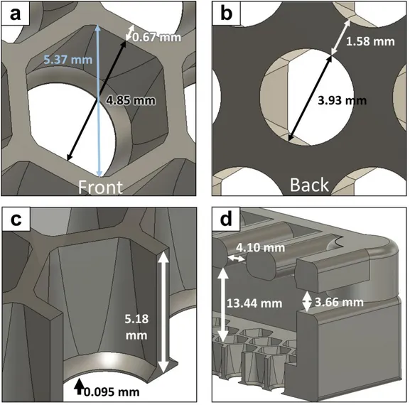
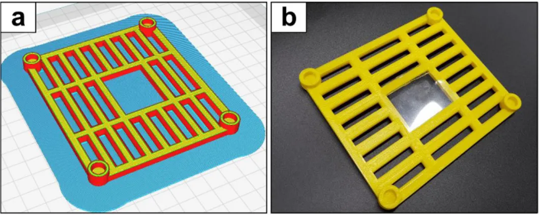
Figure 4. Specification of FECS comb box and queen excluder a Front view of a
cell unit b back view of a cell unit c cross section view of a cell unit d cross section view of a comb box and queen excluder ...14
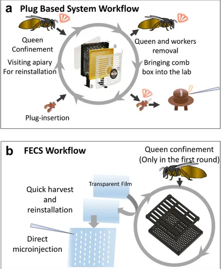
Figure 5. Schematic diagram of the plug-based queen rearing system and FECS a
Workflow of egg collection and microinjection using the Royal queen rearing kit.
b Work flow of egg collection and microinjection using FECS. Eggs can be
harvested continuously without repeated queen confinement. Collected eggs can be readily applied to experiments like microinjection ...16
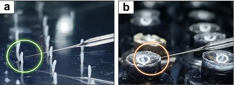
Figure 6. Comparison of flim and plugs as an egg harvesting platform a
Approach of the needle is not hindered during injection of the embryos collected on a film. b Microinjection to posterior end is hindered by the concave structure of the plug. ...17
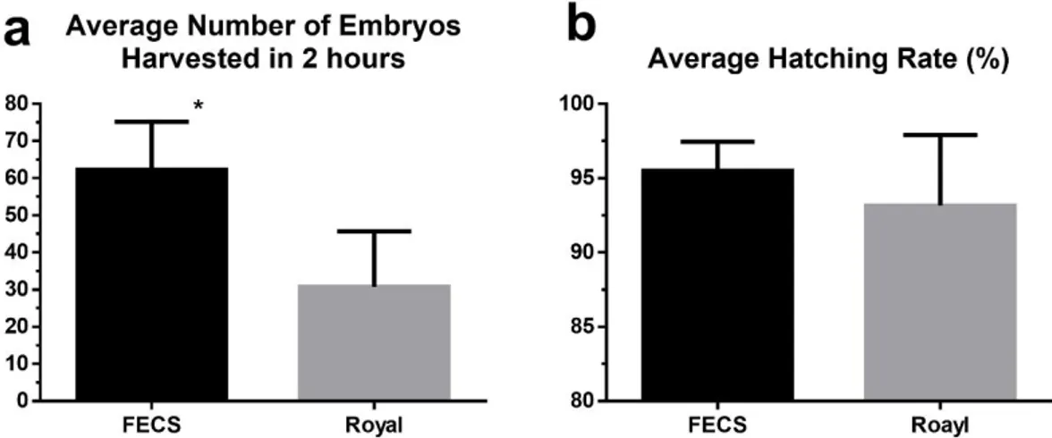
Figure 7. Hatching rate comparison of Royal queen rearing kit and FECS a High
hatching rate was recorded in FECS (95.5%) as in the Royal queen rearing kit (93.2%). b FECS showed significantly higher egg yield (62.3 eggs/ 2 h) than Royal queen rearing kit (30.8 eggs/ 2 h). ...19
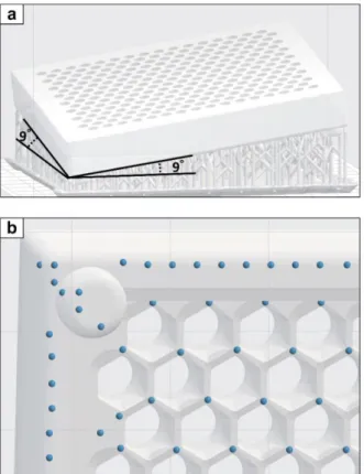
Figure 8. Generation of supports a A comb box model positioned in 9° angle and supports generated using Preform software (Formlabs). b Distribution of support touchpoints over a comb box. ...25
Figure 9. 3D printing and door attachment of the queen excluder a Preparation of
software (Ultimaker B.V., Geldermalsen, Netherlands). b A printed queen excluder with a flippy film door attached...28
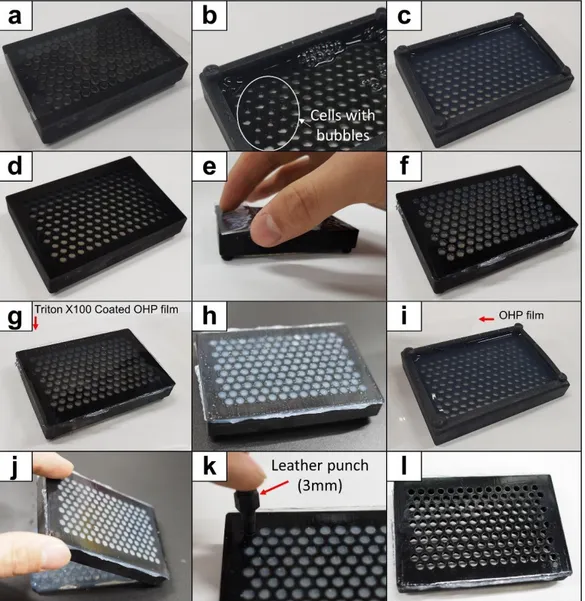
Figure 10. FECS Silicone coating procedure shown with 140-cell comb box. The
same procedure is applied to the standard 256-cell comb box. a Sticky tape attached to the back side of the FECS comb box. b 1% agar poured into the cells with some remaining bubbles. c Solidified agar without critical bubbles. d Agar-masked comb box. e Silicone scraping with a slice of slide glass. f Roughly coated comb box. g Surfactant coated film attached to set to touch state silicone. h Silicone surface after film removal i Detaching agar from comb box wall. j Agar removal with tapping. k Hole punching with 3mm leather punch. l Silicone-coated 140 cell FECS comb box ...34
Figure 11. Diagram and picture of FECS without silicone coating. a FECS unit
using rubber bands and glass plate to fix the film (Front view). b Hind view of FECS unit with rubber bands. Eggs can be collected as long as the comb box is not warped. Reduced warping can be achieved by adopting resins with enhanced physical property. ...36
CHAPTER 2.
Knockout of Nicotinic Acetylcholine Receptor a6 Subunit (nAChR a6) in the
Western Honey Bee, Apis mellifera - The Application of FECS to Genome Editing
Figure 1. sgRNA design to induce DSB in Am nAChR a6 gene. DSB occurs +27
highly conserved transmembrane domain, knock out event is likely to be induced even without frameshifting. ...47
Figure 2. Sequence of ssODN used as HDR template for G275E mutation. The
ssODN consists of 50 bp homology arm (left and right, respectively) and sequence to be altered, including recoded sequence ...49
Figure 3. Fluorescent image of honey bee embryos in early developmental
process. The cleavage cycle over time can be estimated from the number of nucleus. ...55
Figure 4. Digestion of nAChR α6 PCR product by sgRNA-Cas9 RNP. The 615
bp PCR product was digested into 459 and 156 bp fragments. ...56
Figure 5. Plot of injection batches based on average age of embryos at injection
and hatching rate. Hatching rate of embryos increased with the embryonic age at injection ...59
Figure 6. Indels detected from the mutant F1 drones. 7 different types of indels
were found from 8 mutant drones. First two digits of the drone’s name indicate the name of the queen which laid the drones. Drone 18-8 and 18-18 had same 7 bp deletion. Insertion events were observed from two mutants (18-10 and 18-17). I (ATC) to T (ACC) mutation (-6 bp from DSB) was also found in 18-23 drone ...61
Figure 7. Bioassay result of F1 Drones. The two KO mutant died at 7 and 14 h
after topical application of spinosad, both of which belongs to the range recorded in wildtype drones ...62
Figure 8. Dorsal (a) and ventral (b) view of nAChR α6 KO Drone (18-8) ...62
develop. Orange dots indicates genome edited nuclei, whereas blue dots indicate nuclei which were not affected by Cas9 RNP. OF18, in accordance with the scenario, showed the highest germline genome editing rate ...63
1 2 3
CHAPTER 1.
4 5 6Development of Film-assisted Honey Bee Egg Collection
7
System (FECS)
Development of Film-assisted Honey Bee Egg Collection
System (FECS)
Abstract
Despite the huge potential of genome editing in honey bee research and breeding program, only a few successful cases have been reported so far, implying the presence of several obstacles. One of such obstacles is the difficulty in obtaining large quantity of young eggs. To facilitate overall procedures for embryo collection and microinjection, I developed the film-assisted honey bee egg collection system (FECS), in which a removable transparent film is used as the platform for consecutive collection and injection of embryos. FECS provides a significantly higher collection efficiency and usability compared to the conventional plug-based queen rearing system while maintaining a high hatching rate. The system can be readily utilized for various researches that require a large number of honey bee embryos, including honey bee genome editing.
1. Introduction
The western honey bee, Apis mellifera, plays a pivotal role in the pollination of many crop plants, thereby being one of the key elements of modern agriculture, and produces honey and other useful hive products(Klein et al., 2007). In addition, honey bees have a variety of interesting biological features, including polyphenism, polyethism, swarming etc., unlike typical model insects, such as
Drosophila and Tribolium. Despite such economic importance in agriculture and
the value as a unique model with unusual biological characteristics, researches on honey bee biology have been limited by the lack of the classical reverse genetic tools. Although transgenesis and genome editing, in particular, have huge potentials to be utilized in both honey bee researches and breeding programs, they have not been available to honey bee researchers until the first report of transgenic honey bee by Schulte et al. in 2014 (Schulte, Theilenberg, Muller-Borg, Gempe, & Beye, 2014).
Despite various attempts for germline transformation in honey bees (Pen, 2018; Robinson, Ferguson, Cobey, Vaessin, & Smith, 2000), microinjection to young embryo has been the only successful method for the delivery of manipulated genetic materials, leaving the egg collection as the first prerequisite(Hiroki Kohno & Kubo, 2018; H. Kohno, Suenami, Takeuchi, Sasaki,
for honey bee egg collection either in small (Collins, 2002; Milne Jr, Phillips, & Krell, 1988; Taber, 1961) or large (Evans, Boncristiani, & Chen, 2010; Omholt, Hagen, Elmholdt, & Rishovd, 1995) quantities. Among these, the plug-based queen rearing kits have been commonly employed for successful transgenesis and genome editing researches (Hiroki Kohno & Kubo, 2018; H. Kohno et al., 2016; Schulte et al., 2014) as they enable collection of intact eggs with minimal damage. It appears that collection of intact eggs is crucial because embryos in early stages are particularly fragile (Collins, 2002).
In the plug-based system, the plugs are inserted one by one into the back of the plastic honeycomb, and queens are allowed to lay eggs onto the plugs. Harvesting the plugs without any direct contact of eggs ensures the collection of high quality eggs. In this method, however, egg collection efficiency is limited because only 1/3 of cells can be used for the installation of plugs. Also, repeated removal and re-confinement of the queen and worker bees are required whenever plug is installed and retrieved. There are more chances for accidental physical damages that can be given to eggs during such complex procedures. Furthermore, the concave structure of plug bottom hinders the approach of injection needle to the posterior end of embryos, thereby impeding efficient injection (Fig 6).
report the film-assisted honey bee egg collection system (FECS) that provides simplified procedures and significantly enhanced egg collection efficiency. Acquisition of a large number of high-quality honey bee eggs of any embryonic stage via FECS would greatly facilitate the transgenesis or genome editing of honey bees.
2. Materials and methods
2.1. Source of honey bees
Bees were maintained at an apiary located on the rooftop of an eight-story building in Seoul National University, South Korea. Queens were Italian hybrids with some potential Carniolan backgrounds. Two 5-month-old sibling queens were used for comparison test. The numbers of bees in each hive were adjusted to a similar level, both being maintained in two-story hives, each with one super and 10 frames. Both colonies were fed sufficiently with pollen patties throughout the experiment whereas sugar syrup was not provided.
2.2. Design, 3D printing, and post processing of FECS components
Prototypes and final version of FECS components (queen excluder and comb box) were designed using Fusion 360 program (Autodesk inc, San Rafael, CA, USA). For high resolution printing of the comb box, a SLA (stereolithography apparatus) type 3d printer (Form2; Formlabs, Somerville, MA, USA) was used. Supports were generated using the Preform software (Formlabs), and support-added comb box model was printed with a z-axis resolution of 50 μm. Printed boxes were soaked in 90% isopropyl alcohol (IPA) for 15 min and supports were
radiation (395 nm) to the back and front sides of boxes for 10 min each. The back side of the cured comb boxes was coated with silicone rubber using aquarium sealant (Marineland® 31003; Spectrum Brands Pet, Blacksburg, VA, USA). The front surface of the comb boxes was rubbed with beeswax in advance to promote comb building.
Queen excluders were printed with FDM (fused deposition modeling) type 3d Printer (DP200; Sindoh, Seoul, Korea), which has better accessibility with less printing cost compared to SLA type 3d printer. Supports were generated using 3d Wox software (Sindoh) and prints were directly used after removing supports and adding a film door.
The transparent polyester film, conventionally used for overhead projector (OHP), was purchased from local stationary store and used as the platform, onto which queens were guided to lay eggs.
2.3. Use of plug-based system
Description of the plug-based system is based on the Royal queen rearing comb box, which is a part of the Royal queen rearing kit (Yasaeng inc, Gwangju, Korea). The kit was fixed to a Langstroth deep frame as shown in Fig 1b. The frame was installed in advance to let worker bees build wax comb on the plastic
Figure 1. Diagram and picture of FECS and Royal queen rearing system used for
yield comparison test a FECS installed in a plastic frame housing. b Royal queen rearing comb box installed in a Langstroth deep frame.
2.4. Comparison of collection efficiency and hatching rate
For the egg collection by FECS, queens were placed into the FECS unit by relocating them directly from the brood frame. Queens were encouraged to move toward the comb box by themselves instead of transferring by hand to reduce the risk of stressing queen bees. To minimize any putative effects of residual queen pheromones on the behavior of worker bees, designated FECS or Royal queen rearing kit was provided to each queen. Queens were confined to the comb box for 120 – 130 min and the number of harvested eggs per 120 min was calculated. Films were collected at the apiary and brought into the laboratory using a plastic chamber filled with 30˚C water saturated with K2SO4. The number of the eggs on
the film was counted, and films were stored at 34˚, 95% humidity for 80 h.
As for the egg collection using the plug-based system, queens were confined to the Royal queen rearing comb box for 24 h before experiment in order to pre-fill the plugless cells with eggs. Then, the queen bee was transferred to the queen cage, the plugs were replaced, and the experiment was initiated by placing the queen and retinue bees back into the comb box. To harvest eggs from royal queen rearing comb box, bees were removed by gentle shaking and brushing. Frames with comb box were brought into the laboratory and plugs were removed at room temperature (24˚C). Plugs with egg were inserted into plastic pipette tip box (Fig
2) within 15 min from the removal from the frame, and stored at 34˚, 95% humidity for 80 h. The number of hatched larvae was counted at 80 h time point. The frame housing the FECS (Fig 1a) or Royal queen rearing kit (Fig 1b) was inserted in between the 1st and 3rd frames of supers where eggs were laid by the queen bee. All egg collection experiments, either using the FECS or Royal queen rearing kits, were conducted in parallel during the same period of season (late September).
2.5. Statistical analysis
T- test was performed to identify statistical significance in the egg yields and hatching rate between FECS and Royal queen rearing kit using GraphPad Prism 6 software.
Figure 2. Plugs aligned on a micropipette tip box. Boxes were stored at incubator
upside down. Cardboard covered with paper towels were used to fill the gap between the lid and plugs.
3. Results
3.1. Specification of FECS components
The FECS unit is composed of three major components: the plastic comb box, queen excluder and the film (Fig 3a). The standard comb box consists of 256 cells (16*16), and the diameters of inscribed and circumscribed circles of each hexagonal cell are 4.85 mm and 5.37 mm, respectively (Fig 4a, b). The cell wall is 0.67 mm-thick, which allowed reliable 3d printing with SLA 3d printers. The wall height from the back side is 5.18 mm (Fig 4c). The opening of the queen excluder is 4.1 mm, and the gap between comb box and the queen excluder is 3.66 mm (Fig 4d). The space between the queen excluder and the comb surface is 13.44 mm (Fig 4d). Backside of the comb box was designed to have large surface area for tighter film attachment. The circular opening on the back side has 3.93 mm diameter (Fig 4b). The queens were found to lay eggs normally into the fabricated cell units without any extra comb building by worker bees.
Figure 4. Specification of FECS comb box and queen excluder a Front view of a
cell unit b back view of a cell unit c cross section view of a cell unit d cross section view of a comb box and queen excluder
3.2. Feature of FECS
The major feature of FECS distinct from conventional egg collection systems is that the removable OHP film is used as the platform for egg laying (Fig 3a, c), which can be subsequently detached for egg collection and consecutive in situ injection. The film is attached to the back side of the comb box. The flexible nature of the film enables the easy attachment/detachment processes and the tight contact with the back side of comb box coated with silicone (fig 3b). The simple detachment process allows mass collection of eggs of any embryonic stages. The transparent nature of film enables easier observation of oviposition without removing queen excluder and brushing out bees. Unlike the cumbersome procedures of plug collection and reinstallation, which necessitate removing the queen and workers from the comb box as well as bringing the comb box from the apiary (Fig 5a), the film can be readily harvested and reinstalled on site in the apiary within a minute without repeated removal and confinement of the queen (Fig 5b). As eggs are attached on the flat film surface with the original alignment maintained, they are ready for consecutive microinjection without additional alignment or disturbance by the surrounding structure (Fig 6a, b).
Figure 5. Schematic diagram of the plug-based queen rearing system and FECS a
Workflow of egg collection and microinjection using the Royal queen rearing kit.
b Work flow of egg collection and microinjection using FECS. Eggs can be
harvested continuously without repeated queen confinement. Collected eggs can be readily applied to experiments like microinjection.
Figure 6. Comparison of flim and plugs as an egg harvesting platform a Approach of the needle is not hindered
during injection of the embryos collected on a film. b Microinjection to posterior end is hindered by the concave structure of the plug.
3.3. Comparison of collection efficiency and hatching rate
To investigate the overall performance of FECS and the Royal queen rearing comb box (plug type), I compared the collection efficiency and hatching rate between these two egg collection systems. Within 2 h after the confinement of the queen for egg laying, 62.3 eggs in average were collected by FECS, which is more than twice of the number (30.8 eggs) collected by the Royal queen rearing comb box (p=0.019, Fig 7a), demonstrating the significantly enhanced egg collection efficiency of FECS. Although no significant differences were observed in hatching rate comparison, eggs collected by FECS showed a slightly higher hatching rate (95.5%) than those by the Royal queen rearing comb box (93.2%) (p=0.39, Fig 7b).
Figure 7. Hatching rate comparison of Royal queen rearing kit and FECS a High
hatching rate was recorded in FECS (95.5%) as in the Royal queen rearing kit (93.2%). b FECS showed significantly higher egg yield (62.3 eggs/ 2 h) than Royal queen rearing kit (30.8 eggs/ 2 h).
4. Discussion
I have developed a novel honey bee egg collection system that is optimized for microinjection of embryos, which should facilitate downstream processes in transgenesis or genome editing. The adoption of transparent film and silicone coating enhanced collection efficiency significantly and simplified overall collection protocol (Fig 5). Before completing the current version of FECS, various types of egg-collecting materials, including integrated plugs, beeswax, parafilm and parchment paper, had been tested. Among those, only the OHP film satisfied all the criteria of removability, flexibility and durability. The silicone coating was necessary to ensure the performance of FECS as the long-term use of printed comb box usually resulted in a slight distortion of the box and eventually left the gap between the box and film. Queens were observed to be hesitant to lay eggs in such comb boxes until workers filled the gaps with beeswax. Silicone coating gives tolerance to such distortion by ensuring tight adhesion of the film onto the back side of the comb box.
In our collection efficiency comparison, the plug type comb box showed a significantly lower collection efficiency than FECS even though the plugless cells were pre-filled with eggs before the beginning of experiment. This finding
suggests that, if empty cells are scattered around the honeycomb, the queen may spend extra time to find them.
The full egg collection capacity of FECS estimated during the spring season (120–180 eggs/2 h), which was almost identical to the intrinsic egg laying capacity of a queen bee, is much larger than the currently reported egg collection efficiency (i.e., 62 eggs/ 2 h) that which was estimated during the fall season. Therefore, the collection efficiency of FECS is likely more dependent upon the egg laying capacity of a queen bee, which changes due to various factors, including seasonal temperature fluctuation, worker bee number and available food resource.
By employing FECS in genome editing experiment (Chapter 2), a total of 1,900 eggs could be routinely collected in 20 days by a single person while carrying out beekeeping, egg collection, microinjection and grafting. For any researcher with average experience in beekeeping and microinjection, this number of eggs collected by FECS would be enough for any subsequent procedures, and at least would not work as a limiting factor in the whole procedures of successful honey bee genome editing.
Aside from the usage for the honey bee genome editing, the FECS can be applied to other researches. For instance, when applied to toxicity assessment, it
embryonic development and their ovicidal activity. The FECS can be also employed for the honey bee developmental biology. In honey bee, it is unclear yet about the location and timing of the germ cell development as well as the exact mitotic cycles of embryos (Cridge et al., 2017; Dearden, 2006; Pires, Freitas, Cristino, Dearden, & Simoes, 2016). As transparent nature of the film enables the real-time observation of egg laying from the back side of the comb box, researchers can easily record or mark the egg, thereby being able to obtain a large quantity of eggs with known ages. Recently, Fine et al. developed the Queen Monitoring Cage (QMC) to monitor honey bee egg laying under laboratory condition and evaluated the effect of pollen source (Fine et al., 2018). As the authors mentioned, the QMC can be improved further for the enhanced egg laying capacity by queens, and thus the optimization based on the use of film and silicone coating as in the FECS can be a feasible option.
Chapter 1 Appendix
User Guide of Film-assisted Honey Bee Egg Collection System
(FECS)
Contents
Part I. 3D Printing of FECS Comb Box and Queen Excluder Part II. Silicone Coating of the Comb Box
Part III. Installation, Egg Harvesting Manual.
Part I. 3D Printing of FECS Comb Box and Queen Excluder
FECS consists of three major parts: the comb box, queen excluder, and transparent film. Among them, the comb box and queen excluder have to be built with 3D printers. I recommend outsourcing as there are many local companies that offer 3D printing services. Printing service will cost around 70-200 USD per unit. If you have your own 3D printer, the printing will require only 5-40 USD worthy materials. This figure is based on the price in 2018, South Korea. If you decide to outsource the 3D printing service, always be aware that the supports should not be generated on the back side of the comb box and the surface has to be as smooth as
1. 3D Printing of the Comb box
The comb box is the most important component of FECS. In order for FECS to work properly, the comb box must meet the two requirements: 1) the rear side to which the film is attached has to be flat and smooth; 2) the surface and edges of the honey comb structure has to be smooth and uniform. To satisfy these requirements, the comb box has to be made with high resolution 3d printing method, and SLA (DLP) type 3d printer can achieve the above conditions at relatively low cost. Following protocol is based on the use of ordinary bottom-up SLA Printer. If you are using a high-end top-down SLA printer, support conditions may vary and I recommend following the manufacturer’s manual.
1.1 Opening and orienting of the model
Open the provided stl file using software compatible with your 3D printer. Orient the model so that the film-attaching side faces the air. Tilt both sides of a corner of comb box to form 9˚ angles from the build platform (Fig 8a). Tilted printing improves the overall quality of your prints.
Manually create a support structure. Supports should be connected to every other corner of each hexagonal comb (i.e., three touchpoints per a cell, Fig 8b). Be careful not to create supports either inside the comb wall or the back side (smooth side) of the comb box. Insufficient number of supports will create poor quality prints.
Figure 8. Generation of supports a A comb box model positioned in 9° angle and supports generated using Preform software (Formlabs). b Distribution of support
1.3 Printer inspection and beginning of printing
Check the printer status and proceed with printing. The printer should be operated after checking whether the amount of resin is sufficient, the bottom surface of the resin tank is clear, and there are no impurities in the resin. Always follow the safety rules of 3D printer and resin manufacturer. The recommended printing resolution is 25 or 50 μm. It takes around 3 - 16 h depending on the printer type and resolution.
1.4 Post processing and supports removal
Immerse prints in isopropyl alcohol or ethyl alcohol for 10-20 min according to the guidelines of the resin and printer manufacturer. It is recommended holding the print with a large tweezers, rinsing for 20 seconds, and soaking for 15 min.
Remove the prints from the alcohol, then dry at room temperature for 10 min to remove the alcohol. Remove supports from the print when the alcohol is dry. Supports can be easily removed by holding the prints and raft in each hand and then exerting force in the opposite direction. The remaining supports can be removed using a cutting plier.
405 nm UV radiation is required for curing of the prints. If no UV curing machine is available, prints can be cured with sunlight or a gel-documentation
the front and back sides for 5-10 min respectively, depending on the light intensity. Immersion for longer than 1 h and excessive UV radiation may cause deformation of the print.
2. 3D printing of the Queen Excluder
The queen excluder allows the worker's access while confining the queen on the comb box. I printed queen excluders using FDM 3D printers and PLA filaments for cost savings and mass production. Although overall print quality from FDM printer was lower than that of SLA, no apparent problem was noticed when using the printed queen excluder.
2.1 File importation, orientation, and support generation
Open the stl file using any software that is compatible with your 3D printer. FDM printing does not require tiling of the model. Orient the lid so that the top of the lid faces the bottom of the bed for printing convenience. Create supports through the tools provided by the software. It is recommended creating raft for reliable printing (Fig 9a).
Figure 9. 3D printing and door attachment of the queen excluder a Preparation of
queen excluder printing with FDM printers. The image was generated using Cura software (Ultimaker B.V., Geldermalsen, Netherlands). b A printed queen
excluder with a flippy film door attached.
2.2 Printing
We had good result with 0.4 mm nozzle. Z-axis resolution of 0.2mm is recommended. You can print more than one product at a time, depending on your printer's capacity. I recommend 20% to 30% infill. It takes about 4 - 16 h depending on the type and setting of the printer.
2.3 Supports removal and attaching film door on the entrance.
queen excluder makes it easier to insert the queen (Fig S5b). I recommend using silicone glue (Aquarium sealant 31003, Marineland Spectrum Brands, VA, USA) as the coating substance.
Part II. Silicone Coating of the Comb Box
Although it is not mandatory, silicone coating on the back side of the comb box is highly recommended. The coating not only guarantees tight adhesion of the film after repeated usage, but also makes it easier to attach and detach the film. Although there are many types of silicones available in the market, I have only confirmed the effectiveness of the Marineland® aquarium sealant 31003 (Spectrum Brands Pet, Blacksburg, VA, USA). As the set-to-touch time of silicone sealants or glues can differ between product lines and manufacturers, I recommend the use of the same product in this guide.
Materials
Leather Punch (3mm) FECS comb box (cured)
Glass plate (recommended)
1g of Triton-X 100 or Dish washing liquid (surfactant) 5ml Ethanol (96% or absolute)
OHP film Kimwipe
1. Preparation of surfactant-coated film.
Add 1g of surfactant (for dish washing) or Triton-X 100 to 8 ml Ethanol. Mix thoroughly and apply 1ml of the mixture on a clean OHP (overhead project) film. Spread the solution on the film so the film can be coated with the surfactant. The surfactant-coating area of the film must be large enough to completely cover the entire back side of the FECS comb box (12cm x 11cm for standard 256 cell unit). Dry the solution in the room temperature. Cover the film with baskets to prevent dust landing on the surface.
2. Taping (Fig 10a)
Attach sticky tape over the back side of the comb box to seal the bottom openings of combs.
Prepare 1% agar by adding 1 mg of agar to 100 ml tap water using a microwave oven. Boil the mixture until the agar dissolve thoroughly. Cool down the agar solution to 55-60°C. Pour the agar over the top of the taped comb box to fill all the combs.
4. Bubble inspection (Fig 10b, c)
Gently tap the comb box to remove air bubbles in the cells. Inspect thoroughly and remove any remaining bubbles using a 1000 p pipette. Remaining bubble will make empty space in the agar and allow silicones to smear into the space. Silicone cannot be removed easily once stick to the cell wall. Solidify the gel for 30 min at the room temperature.
5. Tape removal and silicone coating (Fig 10d, e, f)
Remove the sticky tape on the back side and wipe out the surface with Kim’s
wipe to remove any water on the surface. Squeeze 4~6 g of Silicone paste (Marineland® 31003) onto the slide glass. Spread silicone over the back side of the comb box by scraping the surface with the slide glass. Scrape 2~3 times while maintaining the glass surface at 10° angle from the comb box. Try to make sure all
silicone to make flat surface whereas excessive coating can make puncture in the next process very hard. Finish scraping within 2 min after silicone squeezing.
6. Flattening of silicone at set-to-touch time (Fig 10g)
Although the surface of the coating already seems flat by the scraping process, the film will not attach evenly without additional flattening process. At 8 min after scraping, gently apply the surfactant-coated OHP film prepared in the step 1. The 8-min time point is critical to adjust the surface texture before complete curing. The set-to-touch time can also change according to the temperature and humidity (Faster curing at high temperature and humidity). The 8 min is based on the conditions of 25°C and 40% RH. Scrape the film so the film can flatten the surface. Remove all the air trapped between silicone and the film. Surfactant (Triton X-100) will block the adhesion of silicone to the film surface. If possible, leave the film on a flat glass plate and gently press the comb box. Stay overnight until the silicone is completely cured.
7. Film and Agar Removal (Fig 10h, I, j)
Remove the film and wash off the surfactant left on the silicone coat. Remove agar using a slice of OHP film and tapping.
8. (Optional) Wax coating
Front coating with beeswax can be applied during this step. Rub the front side of the comb box with beeswax. Wax maintained at 35-40°C will be more easily applied onto the surface. Melt the beeswax with a hairdryer. Try to melt the beeswax in low temperature as possible (the melting point of the beeswax is 62 to 64°C) because exposure to high temperature above 70°C can cause deflection of the comb box.
9. Punching (Fig 10k, l)
Bore a hole into the silicone coat by gentle pushing and twisting with a leather punch (3 mm diameter). Remove silicone disks made by punching. Attach a slice of clean OHP film to protect silicone surface.
Figure 10. FECS Silicone coating procedure shown with 140-cell comb box. The
same procedure is applied to the standard 256-cell comb box. a Sticky tape
masked comb box. e Silicone scraping with a slice of slide glass. f Roughly coated comb box. g Surfactant coated film attached to set to touch state silicone. h Silicone surface after film removal i Detaching agar from comb box wall. j Agar removal with tapping. k Hole punching with 3mm leather punch. l Silicone-coated 140 cell FECS comb box
Part III. Installation and egg harvesting manual
1. Assembly of the FECS and the housing
1.1 OHP film
The OHP film is readily available through any office supplies and the internet. Use a box cutter to cut to 10 cm x 10.5 cm in size to match the comb box. If you divide the A4 size OHP film into six equal parts, you can get the right size film. It is recommended keeping the cut film in zipper bag. Attach the film on the silicone-coated surface. Film can be fixed using rubber band and glass plate instead of silicone coating as shown in Fig 11.
the comb box is not warped. Reduced warping can be achieved by adopting resins with enhanced physical property.
1.2 Extruded polystyrene (XPS) board
The XPS board is used to fix the comb box to the frame. Purchase a 10T (10 mm) thick XPS board and cut to the size of the frame. The vertical length of the XPS board should be the same as the inner length of the frame, and the width (width) of 18 cm is recommended. The trimmed XPS board should fit into the frame with a little stiffness. Cut the inside into a rectangle of 109 mm * 95 mm so that FECS can be inserted.
2. Installation and harvesting
2.1 Installation and preparation
Bring the FECS installed frame to apiary and confine the queen inside the FECS unit. Insert the frame in between brood frames. I recommend confining the queen a day before the experiment, thus allowing the bees to get accustomed to the new environment. Visit the apiary next morning and remove the old film and eggs attached on it. Attach new film and wait for 1-3 h depending on your experimental design.
Visit the apiary again and harvest age-synchronized eggs. I recommend bringing an insulated container pre-warmed with a 35°C water bag. Store embryos under a dedicated environment condition until use.
CHAPTER 2.
Knock Out of Nicotinic Acetylcholine Receptor (nAChR)
a6 Subunit in the Western Honey Bee, Apis mellifera
Knock Out of Nicotinic Acetylcholine Receptor (nAChR)
a6 Subunit in the Western Honey Bee, Apis mellifera
-The Application of FECS to Genome Editing
Abstract
Breeding of honey bees with artificial selection and crossing has been one of the most effective methods to acquire honey bee strains with favorable traits. This method, on the other hand, requires a lot of time and effort to obtain desirable results. Recently, advance in CRISPR-Cas9 allowed the first genome edited honey bee, thereby paving another way for honey bee breeding. In this study, I aimed to prove the concept of pesticide-resistant honey bees that can tolerate exposure to environmental pesticide as well as in-hive miticides. By employing FECS in egg collection and microinjection, I could inject more than a thousand honey bee eggs, three of which developed into queens with mutant offsprings whose nicotinic acetylcholine receptor α6 subunit gene is impaired. Although the number of mutant drones was not sufficient for bioassay to prove the concept, I comfirmed that haploid honey bees (drones) can develop into adults, which can be used to phenotype analysis in further studies. Also, the high germline genome editing rate of OF18 queen, which developed from the embryo injected with an
1. Introduction
The survival of honey bee has been threatened by various factors including exposure to pesticides (Henry et al., 2012; Tsvetkov et al., 2017) and spread of parasitic mites (Le Conte, Ellis, & Ritter, 2010; Oldroyd, 1999; Wenner & Bushing, 1996). Use of chemical miticides, such as coumaphos and fluvalinates, has been the most effective way to control parasitic mites; however, extensive use of these miticides has resulted in mite resistance problem, which is one of the serious challenges that can threat the future of apicultural business. Due to the similarities between mites and honey bees in their toxicological targets, however, it is extremely difficult to develop novel and effective miticides that exert selective toxicity only to mites, by which negative impacts to honey bees are minimized. Breeding honey bees with enhanced resistance to certain miticides, thus enabling honey bees to withstand the lethal dose against mites, could be an alternative strategy, but traditional honey bee breeding is very tedious and time-consuming (Oxley & Oldroyd, 2010), requiring more effective measures to modify honey bee’s genetic traits like genome editing.
Until recently, despite its effectiveness, genetic engineering was only applicable to certain types of organisms, either of which genome could be easily manipulated
During recent several years, however, the clustered regularly interspaced short palindromic repeats (CRISPR), originally identified as bacterial adaptive immune system (Barrangou et al., 2007), has been rapidly employed as the major genome editing tool for various organisms including honey bees(Hiroki Kohno & Kubo, 2018; H. Kohno et al., 2016). Theoretically, it is now possible to create honey bees with resistance to certain insecticides, thereby employing them as in-hive miticides or insecticides applicable during pollination season without much negative impacts to honey bees. With this in mind, following experiments were designed to prove the concept of such honey bee breeding through the genome editing based on CRISPR.
One of the two things done at the beginning of this study was to develop a new system for egg collection, thereby increasing the efficiency of egg collection and microinjection, which is essential for successful honey bee genome editing (Chapter 1). The other thing was selecting a proper target gene among a variety of insecticide target genes in honey bee genome. The target gene has to meet following criteria to ensure the successful experiment: 1) The gene has to encode pesticide target protein with well described point mutations that gives resistance to the pesticide, 2) The pesticide has to have different mode of action from existing in-hive miticides, 3) Toxicity of the pesticide against acari should have been
does not affect the survival of mosaic queen. By comparing almost all types of insecticides on the market, I confirmed that spinosyns best meet the above criteria.
First discovered in secondary metabolites of bacterial species
Saccharopolyspora spinosa, spinosad is an insecticide with novel mode of action
distinguished from all other groups of insecticides (Sparks, Dripps, Watson, & Paroonagian, 2012). Since its first introduction to the market in 1997, target site resistance has been reported from several different orders of insects, including Diptera, Lepidoptera, and Thysanoptera (Bao et al., 2014; Baxter et al., 2010; Hsu et al., 2012; Perry, McKenzie, & Batterham, 2007; Perry, Somers, Yang, & Batterham, 2015; Puinean, Lansdell, Collins, Bielza, & Millar, 2013; Somers, Nguyen, Lumb, Batterham, & Perry, 2015; Wan et al., 2018; Zimmer et al., 2016). Interestingly, it was also reported that the knock-out (KO) of nAChR a6, the target protein of Spinosad, confers resistance as well as the G275E point mutation. This unique resistance mechanism provides additional merit to nAChR a6 gene as the target of genome editing since the KO event occurs more frequently than the knock-in event through which point mutation can be inserted into the honey bee genome (Chu et al., 2015; Maruyama et al., 2015).
In this study, I discussed the overall honey bee genome editing procedure after embryo collection, including the ideal condition of microinjection based on the
in nAChR a6 gene of western honey bee and examined the impact of the KO of nAChR a6mutation.
2. Materials and methods
2.1. Honey bee source and egg collection
Western honey bee (Apis mellifera L.) colonies presumed to have both italian and carniolan hybrid backgrounds, were purchased from a local bee keeper. Colonies were maintained at a rooftop apiary of an eight-story building in Seoul National University, South Korea. Eggs were collected using FECS, as described in Chapter1. Eggs were harvested at 120 – 150 min intervals and stored at 34°C and 95% RH until injection.
2.2. DAPI staining and fluorescent imaging
Fluorescent images of embryos in early developmental process (1 ~ 9 h after egg laying) were obtained using Axio Imager A1 (Carl Zeiss, Jena, Germany). Eggs were collected at 1 h interval and stored at 34°C, 95% RH until the embryos reach the age to be fixed. Films were then placed on ice to prevent aging of embryos during the procedure. Embryos were fixed by placing eggs into the 1 ml fixative solution (1:1 mixture of heptane and 4% formaldehyde in PBS) using
removed 12 h later, followed by addition of methanol that was prechilled at -20°C. Upon the addition of methanol, the vial containing embryos were shaken vigorously. Embryos were washed with methanol three times and stored at -20°C until next step. Embryos were rehydrated by removing methanol and adding 495 ml PBTA (1´ PBS with 1% BSA, 0.05% Triton X-100, and 0.02% sodium azide).
To stain nucleus of embryos, 5 ml of 100x DAPI (0.01% DAPI in methanol) was added and stored on a rotator. 1´ DAPI-PBTA solution was washed with 1´ PBS for 30 min, washing was repeated three times. Washed embryos were then cleared with a series of 30, 50, and 70% glycerol and mounted on concavity slides. The fixation protocol was modified from pre-existing protocols (Sullivan, Ashburner, & Hawley, 2000; Wotton, Jiménez-Guri, Matheu, & Jaeger, 2014) referring Osborne and Deardon’s method (Osborne & Dearden, 2005).
Multiple fluorescent images obtained from microscope by manual focusing were stacked using Zerene Stacker (Zerene Systems, Richland, WA, USA). Pictures were further processed with Microsoft PowerPoint for orientation and back ground control.
As I aimed to introduce both KO mutation and G275E point mutation (GGG to GAA or GAG) using SpCas9, protospacer associated motif (PAM) sites near the G275 sequence were listed as candidate sequence. Among those candidate sites, the one located at +31~33 base from the beginning of the exon 9 was selected as the final target sequence (Fig 1) since it has relatively high GC contents at seed region (1-8 base from the PAM site).
Templates for in-vitro transcription (IVT) of sgRNA was produced by polymerase reaction of two single stranded oligo DNA, which have 15-bp overlaps to each other (Table 1). 1 mg of Template DNA and MEGAscript™ T7 Transcription Kit (Thermofisher Scientific, Waltham, MA, USA) were used for IVT reaction following manufacturer’s instruction. After DNase treatment, synthesized sgRNA was then purified with RNeasy® Mini Kit (QIAGEN, Hilden, Germany) following the RNA cleanup protocol provided by the manufacturer. In order to capture sgRNA which is smaller than ordinary mRNA, increased amount of ethanol (270 ml) was added to the mixture of RNA-RLT buffer (50 ml+175 ml). Purified sgRNA was quantified with Nanodrop ND1000 (Thermofisher Scientific) and gel electrophoresis.
Figure 1. sgRNA design to induce DSB in Am nAChR a6 gene. DSB occurs +27 base from the codon of G275,
which is close enough to induce point mutation through homology directed repair (HDR). Since the DSB is in the middle of highly conserved transmembrane domain, knock out event is likely to be induced even without
Table 1. List of Primers used in this study
2.4. Design of single-stranded oligo DNA (ssODN)
To introduce G275E point mutation to the honey bee genome, ssODN was employed as homology-directed repair (HDR) template (Figure 2). The sequence between G275 and DSB site was recoded (silent mutation) in order to promote the incorporation of the edit as described by Paix et al (Paix et al., 2017). The 133-base single strand DNA was purchased from IDT (Coralville, IA, USA).
Figure 2. Sequence of ssODN used as HDR template for G275E mutation. The
ssODN consists of 50 bp homology arm (left and right, respectively) and sequence to be altered, including recoded sequence.
2.5. Cas9 RNP assembly and In-vitro cleavage assay.
Cas9 enzyme (Alt-R® S.p. HiFi Cas9 Nuclease V3) was purchased form IDT. Before the assembly, purified sgRNA re-annealed by slowly decreasing temperature from 80°C to 37°C. Cas9-sgRNA RNP was assembled by mixing mixing Cas9 emzyme, sgRNA, and ssODN in injection buffer (20mM HEPES pH 7.0, 130 mM NaCl, 15 mM KCl, 4 mM MgCl2, 5 mM CaCl2, and 1 mM TCEP at
final concentration) to become 5 µM, 10 µM, and 40 ng/ml final concentration, respectively.
In vitro cleavage assay was conducted to confirm enzyme activity after RNP
assembly. In short, 0.5 pmol (104 ng) of 316-bp substrate DNA was prepared by PCR reaction using primers on table x, was mix with 5pmol pre-assembled RNP at 37°C 30 min. Reaction was stopped by adjusting temperature to 70°C for 10 min.
2.6. Microinjection, in vitro rearing and grafting
Micro injection needle was pooled with lazer pooler P-2000 (Suttur instrument, Novato, CA 94949, USA). The needle back-filled with RNP-ssODN solution was then fitted into pneumatic microinjector that was built according to Handler et al.(Handler & James, 2000). The Needle tip was opened by gentle rubbing with kimwipes under stereomicroscope. The injection volume was controlled by foot pedal and pressure knob to have droplet of 100mm diameter. On average, 300-600 pl of injection solution was expected to be delivered. Cas9 RNP-ssODN solution was injected to either the medial or posterior region of embryos. Age of embryos differed from batch to batch, ranging from 1 h to 12 h AEL (After Egg Laying). During injection, the environment was maintained at 28~31°C and 50-90% RH. Injected embryos were stored at 34°C 95% RH until hatching.
vitro rearing, larvae were then grafted into a queenless colony. Closed queen cells
were moved out 9 day after injection and stored at 34°C and 75% humidity until emergence.
2.7. Maintenance of mosaic queens and F1 drones
On the day of emergence, the queens were marked with different colors and their wings of were clipped. Queens were stored at 31°C and 50% RH until the 6th day after emergence. On the 6th and 8th day after emergence, queens were anaesthetized with CO2 for 7 min to promote laying of unfertilized eggs without
mating. From the 6th day after emergence, queens were introduced to a nucleus hive with the door allocated for each queen. The nucleus hives were maintained in a mosquito net installed in a separate room registered for rearing LMO rearing. To promote egg laying, the pollen patties and sugar syrups were supplied to each colony. Since the number of workers declined continuously during the in-door rearing, colonies were supplemented with nurse bees captured from the roof top apiary.
The F1 drones, which began to emerge from nearly 2 months after the mosaic queen emergence, were kept in the nucleus hive by switching the rotating door into queen/drone excluding state until being collected for bioassay and sequencing.
2.8. Bioassay
To assess the resistance level of mutants, drones were caught a day before the topical application and allowed to feed comb honey ad libitum. On the day of bioassay, ages of each drone ranged from 2 to 6 day after emergence. Although all drones did not qualify as good for bioassay, any drones that were able to walk longer than 5cm were used. A total of eight drones from the OF12 queen and 12 drones from the OF18 queen were used for bioassay.
Analytical standard grade Spinosad (Merck KGaA, Darmstadt, Germany) was diluted with acetone to 100mg/ml, and 1 ml aliquot was topically applicated to the notum of each drone (100mg spinosad/drone). The time until death of each drone was recorded, and drones were then sampled for sequencing.
2.9. Sequencing of F1 drones
A total of 68 drones in various stages were sampled for gDNA extraction and PCR. The samples included dead larvae, pupae, and adults, along with those collected right after bioassay. Parts of collected specimens (2 to 3 legs of adults or equivalent volume of larval/pupal tissue) were flash-frozen with liquid nitrogen in a 1.5-ml centrifuge tube, pulverized with chilled pestle, and then used for gDNA extraction using DNeasy Blood and Tissue kit (QIAGEN). The 316-bp gDNA
of 62 samples passed quality check by gel electrophoresis and their nucleotide sequences were analyzed by the Sanger sequencing method.
3. Results
3.1. Fluorescent imaging of early embryos.
Florescent images of honey bee embryos in different cleavage cycles were obtained to confirm optimal injection site depending on the age of embryos. Unfortunately, I had difficulties in obtaining a large number of high-quality samples mainly due to the delicacy and opaqueness of honey bee embryos, which only allowed rough observation of the process. Nevertheless, my observation conformed to the previous observations by Schnetter et al.(Fleig & Sander, 1986; Schnetter, 1934; Yu & Omholt, 1999)
At 1-2 h AEL, nuclei were found in the anterior end of embryos. As presented in the figure 3a, maternal nuclei at its end of meiosis were seen, whereas a single male nucleus were observed in the middle of anterior cytoplasm. The embryo fixed at 3-4 h AEL had four nuclei, implying the stage to be in-between the 2nd and 3rd mitotic cycles (Fig 3b). Sixteen pairs of nuclei, which refer to the end of the 4thmitotic cycle, were observed in the endoplasm of 4-5 h embryo (Fig 3c). At 6-7 h AEL, approximately 60 to 200 nuclei were observed (Fig 3d, e), whereas roughly 500 nuclei were observed in the embryo fixed 8-9 h AEL (Fig 3f). This information was reflected in establishing the injection scheme for more reasonable
Figure 3. Fluorescent image of honey bee embryos in early developmental
process. The cleavage cycle over time can be estimated from the number of nucleus.
3.2. in-vitro cleavage assay
Most of the substrate DNA was cleaved by the sgRNA-Cas9 RNP, thereby indicating robust biding activity of both synthesized sgRNA and Hifi Cas9 enzyme. The RNP retained activity after more than five freeze-thawing. Since the RNP showed in-vitro activity in injection buffer, the same RNP solution was directly employed to microinjection.
Figure 4. Digestion of nAChR α6 PCR product by sgRNA-Cas9 RNP. The
3.3. Microinjection, grafting, and maintenance
A total of 1667 eggs were injected with various injection conditions (table 2). A total of 253 larvae (15.2%) hatched from the injected eggs and moved to plastic dish prepared for in vitro rearing. Next, I selected 85 larvae for grafting based on healthy appearance and representativeness of each injection batches. A total of 15 queens (17.6%) emerged from the queen cell, and each queen was introduced to exclusive nucleus hives. I lost 12 queens during introduction and maturation process of virgin queens, leaving only three queens that successfully laid unfertilized eggs, which developed into drones. These queens were named after the injection batches, OF12, OF13, and OF18, respectively. Queens began to lay eggs more than a month after emergence.
Although the hatching rate varied even between the batches that were injected under similar conditions, overall tendency of increasing hatching rate depending on the larval age was observed (Fig 5).
Table 2. Injection conditions and results from following procedures. The number
of hatching embryos, grafted embryos, emerged queens and queens with offspring is also noted in the table.
Figure 5. Plot of injection batches based on average age of embryos at injection
and hatching rate. Hatching rate of embryos increased with the embryonic age at injection.
3.4. Sequencing
The OF12 queen, which was injected at 6.4 h on posterior end, produced 29 offsprings, one (3.4%) of which was determined to be a mutant. The OF13 queen, which was injected at 6.9 h to medial point, produced 10 offsprings, with none of which being mutant. OF18 queen, which was injected at 4 h to medial point, produced 23 offsprings, with 7 (30.4%) of which being mutants (Table 3).
A total of eight mutant drones, displaying seven different genotypes, were detected from sequencing of 63 drones. Six drones, including four adults, had
gene (Fig 6). Any knock-in event was not detected.
Table 3. Injection condition of the queens and sequencing result of each queen.
Two out of three queens (66.7%) had genome edited offsprings.
3.5. Bioassay and phenotype observation.
Survival time for each drone was recorded after topical application of spinosad, with the shortest time being 3 h whereas the longest time marked 24.5 h. Among 20 drones tested, only two drones were confirmed as mutant in the subsequent sequence analysis. Mutants drones showed survival times that are similar to those of the wildtype group (fig 7) and did not display any noticeable difference in appearance compared to the wildtype drones (fig 8).
Figure 6. Indels detected from the mutant F1 drones. 7 different types of indels were found from 8 mutant drones.
Figure 7. Bioassay result of F1 Drones. The two KO mutant died at 7 and 14 h
after topical application of spinosad, both of which belongs to the range recorded in wildtype drones.
4. Discussion
In this study, I examined the potential of genome editing technique in generating a honey bee breed with insecticide resistant traits. In order to prove my concept, I selected the honey bee nAChR α6 as the target of editing and demonstrated that honey bee nAChR α6 gene can be knocked-out by injecting Cas9-sgRNA RNP, and adult drone can emerge from haploid egg even without fully functional nAChR α6. To the best of my knowledge, this is the third successful genome editing following Kohno et al. (Hiroki Kohno & Kubo, 2018; H. Kohno et al., 2016) and fifth if transgenic honey bees are included (Otte et al., 2018; Schulte et al., 2014).
Also, I showed that FECS can be readily applied to honey bee genome editing. Plentiful supply of honey bee embryos allowed microinjection with various conditions as well as the unprecedented number total injection counts, both of which can facilitate the optimization of honey bee genome editing technique.
Despite the limited information on honey bee germline formation, honey bee germ cells are also assumed to originate from nuclei in the posterior end of embryo as in most other insects. Based on this assumption, I planned an injection scheme with different injection time and spot from those of Kohno et al. and
Schulte et al. (Hiroki Kohno & Kubo, 2018; H. Kohno et al., 2016; Schulte et al., 2014), both of which injected to posterior end of embryos within 3 h AEL.
Figure 9. Genome editing scenario expected in embryos injected with different
conditions. White circles indicate the location where germline is assumed to develop. Orange dots indicates genome edited nuclei, whereas blue dots indicate nuclei which were not affected by Cas9 RNP. OF18, in accordance with the scenario, showed the highest germline genome editing rate.
Although it is almost impossible to draw meaningful conclusion from the limited number of observations, which is only one sample per condition, the
9). The OF18 queen, which was injected to medial region at 4 h AEL, showed a high germline genome editing rate of 30.2%. In contrast, when injected either at 6.9 h to medial region (OF13) or 6.4 h to posterior end (OF12), the germline genome editing rates were reduced to 0% or 3.4%, respectively. It appears that the injection to the medial region of embryo at a relatively early embryonic stage when smaller numbers of nuclei exist (i.e., 4 h AEL) increased the ratio of genome-edited cells compared to the injection at a later time (i.e., 6.4 AEL). Thus, it can be speculated that the injection timing (i.e., age of embryo at injection) is one of the factors determining the success rate of germline genome editing. The high germline genome editing rate of OF18 which targeted medial part of embryo at 4 h AEL, also supports the result of Otte et al.(Otte et al., 2018), which achieved increased germline transformation rate by adopting anterior injection to early stage of embryo (i.e., 1.5 AEL). Further optimization can be achieved when more samples with different injection timing and spot are available, and the genome editing rate in the ovary is analyzed through deep sequencing.
One of the problems during this study was the low hatching rate of injected embryos. Although different injection batches are expected to produce inconsistent results, those with similar conditions (e.g. OF15 to 16 and OF14 to 28) also showed fluctuating results, implying that other factors, along with expertise