Tracing Algorithm for Intelligent Snake-like Robot System
Woo-Kyung Choi, Seong-Joo Kim and Hong-Tae Jeon
School of Electrical and Electronics Engineering, Chung-Ang University, Seoul, Korea (Tel : +82-2-820-5297; E-mail: [email protected])
Abstract: There come various types of robot with researches for mobile robot. This paper introduces the multi-joint snake robot having 16 degree of freedom and composing of eight-axis. The biological snake robot uses the forward movement friction and the proposed artificial snake robot uses the un-powered wheel instead of the body of snake. To determine the enable joint angle of each joint, the controller inputs are considered such as color and distance using PC Camera and ultra-sonic sensor module, respectively. The movement method of snake robot is sequential moving from head to tail through body. The target for movement direction is decided by a certain article be displayed in the PC Camera. In moving toward that target, if there is any obstacle then the snake robot can avoid by itself. In this paper, we show the method of snake robot for tracing the target with experiment.
Keywords: Mobile Robots, Snake, Modular Robot, Collision Avoidance
1. INTRODUCTION
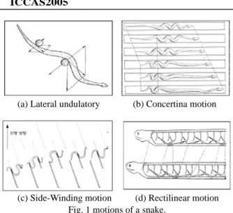
Structure and various character of a biological snake to realize snake robot were researched. The backbone of a snake consists of over 300 and its joint can shift with perfect freedom. A framework of snake is simpler than different vertebrates to the number and the form and consists to 3 parts of skull, backbone and rib. The body is covered with overlapping scales and skin that consist on scale and flat acts role that prevent dehydration of body. A snake hears and divides voice by sensing minute oscillation that occurs on the ground through skin. The scale has been covered on snake skin at regular intervals from front to back. Therefore, tail of snake does moving forward because frictional force acts mainly backward if snake bend its body. And if snake unfold circumflex body, fore-end of snake is advanced by frictional force of tail. If these movements become accustomed, a snake can move with the fast velocity that whole body does not touch on surface of land and it use only body part. The basic motions of snake divide into 4 motion of lateral undulatory motion, rectilinear motion, concertina motion and side-winding motion[1][2][3].
The robot industry is developing from the manufacturing industry to the various fields. At present, not only the robot for exercise of human arm and exercise of the lower part but also the robot that imitate various animals and the robot that express emotion of human are growing. Also in everyday life we are widely utilizing human-friendly robot that accomplish similar action of human in the dynamic environment. Such the development of robot technique has brought entrance of intelligent robot and we are showing an interest in it. In this paper we studied intelligent snake robot that use a sort of robot for probes. The robot that imitate snake is easy to run in the complex environment and it don’t fall on its back.
An aim in the paper is that the snake robot distinguishes between obstacle and target using vision information and sensor information that get by autonomous traveling in complicated environment that have obstacles. And we do the experiment of minimum course that snake robot arrive at goal through avoidance of obstacle by a specified motion that a biological snake move. A snake robot consist of 8 module that use 16 linear-linked servo motor and each module have 2 degree of Freedom. In the main discourse we described movement and motion method of a biological snake and interpreted a moving theory that it advance to direction that want. We calculated the joint angle of each link by analysis of the structure of system and the inverse kinematics of system to realize mechanical snake robot that act like biological snake. We proposed tracing algorithm using minimum path that arrive at a target point through avoidance of obstacle when obstacle is forward direction. Experiment result was simulation based on algorithm proposed and applied to snake robot in online. Conclusion in the paper interpreted the supplementary matters and the action character of snake robot and took notes of the later assignment.
Lateral undulatory motion is most general way of moving sneak. This way use a configuration or things of the ground. Side-winding means that it moves with contacting ground of two part of a sneak when the back side of sneak instantly stops moving. The fore part is moving to upper side and front. After this, the back side also moves same as the front. Rectilinear motion is like this. First, the snake put their scale into a ground and they push up their inner body to front side. Next, they pull over their skin. Concertina motion that is one of snake movement is method for a slippery road, an alley or situation that can not use surrounding topography(Fig. 1-(b)). This method push and stretch out long the front of body until search place that can support body after snake fold body like wind-chest of accordion. And snake pulls the backside of body if it searches the place that can pull supporting. After it stretch out the front of body again, it newly search place that can pull supporting. Concertina motion, movement method that repeats contraction and relaxation like accordion alternating between the front of body and the back side of body, is the most suitable way that can realize motion of snake robot[2].
2. SNAKE ROBOT CHARACTER AND
STRUCTURE
Fig.3 shows a diagram of the snake robot’s heat part. A main controller of the head part transmits six joint angles’ value to be processed by main computer, actuator number of each link and actuator velocity to each module by using serial protocol. A main controller transmits signals to receive from sub controller to a main computer. And it also transmits signals from USB PC Camera and ultrasonic sensor, which are color and distance information about target and obstacle to a main computer.
(a) Lateral undulatory (b) Concertina motion
B. Sub-Controller of the body part
Sub modules to drive servo motors modulate received signal by serial protocol to PWM which is a motor control signal. PWM makes motor drive in a proper angle. Specific criteria is following this. Data to transmit consist of the own number of servo motor, velocity and value of angle. Sub controllers distinguish servo motors with using the own number of servo motor. Therefore, the signal to be transmitted from a main controller is transmitted to a proper sub module correctly. A servo motor is operated by using values of velocity and link. A module which is a minimum unit in control of a sub controller has two servo motors to guarantee two degree of freedom, and AT89C2051 of ATMEL is used with each motor as a controller. Two AT89C2051 in a sub module operate two servo motors after all.
(c) Side-Winding motion (d) Rectilinear motion Fig. 1 motions of a snake.
2.2 The constitution of robot system
With considering features and moving in advance of a biological snake, a frame of the snake robot was designed. The snake robot has seven links and twelve degrees of freedom which are implemented using twelve linear-linked servo motors(Fig.2). The snake robot consisted of main controller used as one link and six sub controllers, and each sub controller controls two servo motors.
Sub Controller 89C2051 TX F rom Ma in Modu le Reset Servo Motor 605BB PWM Sub Controller 89C2051 Servo Motor 605BB Sub Controller 89C2051 TX F rom Ma in Modu le Reset Servo Motor 605BB PWM Sub Controller 89C2051 Servo Motor 605BB
Fig. 4 The body block diagram of snake robot. Figure 5 show us a module that it constitute vertically connection of two servo-motor.
Fig. 2 Multi-joint snake robot. A. Composition of the head part
Fig. 5 Body module of snake robot.
3. INVERSE KINEMATICS EQUATION OF
SNAKE ROBOT
We proposed motion pattern that travel to target point by regular repetition movement of concertina motion that is one Fig. 3 Black diagram of head part.
of biological snake’s motions[7]. If obstacle is situated in the front, snake robot avoid obstacle with 2 motion pattern when it is moving by this method. Snake robot distinguish between target(red) and obstacle(blue) as using color information obtained from PC Camera. Range of PC Camera installed on the snake robot is . Also ultrasonic sensor measure the target distance and the obstacle distance. Inverse kinematics can be induced as input of distance and angle information[4][5][6]. ° ± 20 7 4 5 6 4 2 5 4 6 4 5 2 4 6 5 4 7 5 4 6 4 5 2 ] ) sin( ) sin( ) sin( [ ] ) cos( ) cos( ) cos( [ p p y l l l x l l l d − + + + + + + − + + + + + =
θ
θ
θ
θ
θ
θ
θ
θ
θ
θ
θ
θ
(3)
To become minimum distance, joint angle 4, 5 and 6 are calculated by solutions that partially differentiate equation 3 about each joint angle and the calculated result described to the next.
3.1 Inverse kinematics equation
0 )] sin( ) sin( ) sin( [ ] ) cos( ) cos( ) cos( [ )] cos( ) cos( ) cos( [ ] ) sin( ) sin( ) sin( [ 6 5 4 7 5 4 6 4 5 4 6 5 4 7 5 4 6 4 5 6 5 4 7 5 4 6 4 5 4 6 5 4 7 5 4 6 4 5 4 2 = + + + + + × − + + + + + − + + + + + × − + + + + + = ∂ ∂ θ θ θ θ θ θ θ θ θ θ θ θ θ θ θ θ θ θ θ θ θ θ θ θ θ l l l x l l l l l l y l l l d p p
(4)
Figure 5 is a system of coordinates for each link of snake robot[8][9]. A head and a tail belong to link 7 and link 1.
Snake robot divides into 3 parts that consist of a head, a body and a tail and it shifts by repeated moving method. Snake robot catches a target through a gradual probing process when it puts any place. 6 Joint angles that are influenced by input of distance and angle information between snake and goal is calculated by next process.
0 )] sin( ) sin( [ ] ) cos( ) cos( ) cos( [ )] cos( ) cos( [ ] ) sin( ) sin( ) sin( [ 6 5 4 7 5 4 6 4 6 5 4 7 5 4 6 4 5 6 5 4 7 5 4 6 4 6 5 4 7 5 4 6 4 5 5 2 = + + + + × − + + + + + − + + + + × − + + + + + = ∂ ∂ θ θ θ θ θ θ θ θ θ θ θ θ θ θ θ θ θ θ θ θ θ θ θ l l x l l l l l y l l l d p p
(5)
0 )] sin( [ ] ) cos( ) cos( ) cos( [ )] cos( [ ] ) sin( ) sin( ) sin( [ 6 5 4 7 4 6 5 4 7 5 4 6 4 5 6 5 4 7 4 6 5 4 7 5 4 6 4 5 6 2 = + + × − + + + + + − + + × − + + + + + = ∂ ∂ θ θ θ θ θ θ θ θ θ θ θ θ θ θ θ θ θ θ θ l x l l l l y l l l d p p(6)
Result of equation 4, 5 and 6 is the same equation 7.
0 , tan 5 6 4 4 1 4 ⎟⎟ = = ⎠ ⎞ ⎜ ⎜ ⎝ ⎛ = −
θ
θ
θ
p p x y(7)
Fig. 6 Mechanical structure of the snake robot. First step, link 3 and 4 between body and tail are fixed on the ground. At this time actuator 8 and 10 that have verticality degree of freedom maintain as regular verticality angle against the ground because of frictional force. Joint angle 1 and 2 that is between link 1 and link 2 and joint angle 4, 5 and 6 accomplish calculation. First, joint angle 1 about target point maintain fixed angle(0˚) and values of joint angle 4, 5 and 6 are calculate by the next equation. We calculate angle(
γ
) and distance between head of link 7 and target. So we calculate coordinates of target point through joint angle 4 that is based at coordinates and calculate distance from joint angle 4 to target.After finishing first step about target point, the body and the tail with movement distance of head part begin to moving. Second step is moving step of the body and it is the next. Joint angle 1 of link 1, 2 and joint angle 6 of link 7 are fixed by maintenance of angle value of first step on the ground. At this time considering frictional force, angle of actuator 12 maintain as regular verticality. We calculate joint angle 2 and 3 of link 3 and 4 and joint angle 4, 5, and 6 of link 5 and 6. At this time coordinates relation between joint angle 2 that become basic coordinates and joint angle 6 represent as equation 5 and 6.
) cos( ) cos( ) cos( ) cos( 5 4 3 2 6 4 3 2 5 3 2 4 2 3 62
θ
θ
θ
θ
θ
θ
θ
θ
θ
θ
+ + + + + + + + + = l l l l x(8)
) cos( ) cos( ) cos( ) cos( 6 5 4 6 5 4 7 5 4 6 4 5 4γ
θ
θ
θ
θ
θ
θ
θ
θ
θ
− + + + + + + + + = d l l l xp(1)
) sin( ) sin( ) sin( ) sin( 5 4 3 2 6 4 3 2 5 3 2 4 2 3 62θ
θ
θ
θ
θ
θ
θ
θ
θ
θ
+ + + + + + + + + = l l l l y(9)
) sin( ) sin( ) sin( ) sin( 6 5 4 6 5 4 7 5 4 6 4 5 4γ
θ
θ
θ
θ
θ
θ
θ
θ
θ
− + + + + + + + + = d l l l y p(2)
To induce joint angle 2 and 3, distance between joint angle 4 and joint angle 6 show to equation 10.
Joint angle 4, 5 and 6 are induced by the equation 3 to become minimum distance value between a snake robot and a
target. 42 62 2 2 62 42 2 64 (x x ) (y y ) d = − + −
(10)
If we calculate solution of partial differentiation to become minimum value of distance between joint angle 4 and 6, we search joints angle 2 and 3 and the next is the result calculated.
0 )] sin( ) sin( [ ] ) cos( ) cos( [ )] cos( ) cos( [ ] ) sin( ) sin( [ 3 2 4 2 3 62 3 2 4 2 3 3 2 4 2 3 62 3 2 4 2 3 2 2 64 = + + × − + + − + + × − + + = ∂ ∂ θ θ θ θ θ θ θ θ θ θ θ θ θ l l x l l l l y l l d
(11)
0 )] sin( [ ] ) cos( ) cos( [ )] cos( [ ] ) sin( ) sin( [ 3 2 4 62 3 2 4 2 3 3 2 4 62 3 2 4 2 3 3 2 64 = + × − + + − + × − + + = ∂ ∂ θ θ θ θ θ θ θ θ θ θ θ l x l l l y l l d(12)
Result of equation 11 and 12 is the same equation 13.
0 , tan 3 62 62 1 2 ⎟⎟ = ⎠ ⎞ ⎜⎜ ⎝ ⎛ = −
θ
θ
x y(13)
Joint angle 4, 5 and 6 can calculate by application of trigonomentrical function law[5].
Fig. 7 Determine of joints angle 4, 5 and 6.
⎟⎟ ⎠ ⎞ ⎜⎜ ⎝ ⎛ + − = − + = − 64 5 2 6 2 64 2 5 1 4 4 64 5 2 64 2 5 2 6 2 cos cos 2 d L L d L d L d L L
θ
θ
(14)
⎟⎟ ⎠ ⎞ ⎜⎜ ⎝ ⎛ + − = − − + = − 6 5 2 64 2 6 2 5 1 5 5 6 5 2 6 2 5 2 64 2 cos ) cos( 2 L L d L L L L L L d θ θ π(15)
2 6 6 42 2 5 2 6 2 64 1 6 6 64 6 2 64 2 6 2 5 2 cos cos 2 before L d L L d d L d L Lθ
θ
θ
θ
+ − ⎟⎟ ⎠ ⎞ ⎜⎜ ⎝ ⎛ + − = − + = −(16)
Joints angle 2, 3, 4, 5 and 6 that consider at the second step are calculated by operation of the upper equations. The third step keep joint angle 5 and 6 of the second step. And joint angle 1, 2, 3 and 4 move forward a regular distance by maintenance with the same value of first step. Verticality joint angle 2, 4 and 6 of the link 5, 6 and 7 are maintained as fixed
value. In the third step, snake robot goes back to motion of the first step.
4. ALGORITHM FOR OBSTACLE AVOIDANCE
AND SIMULATION
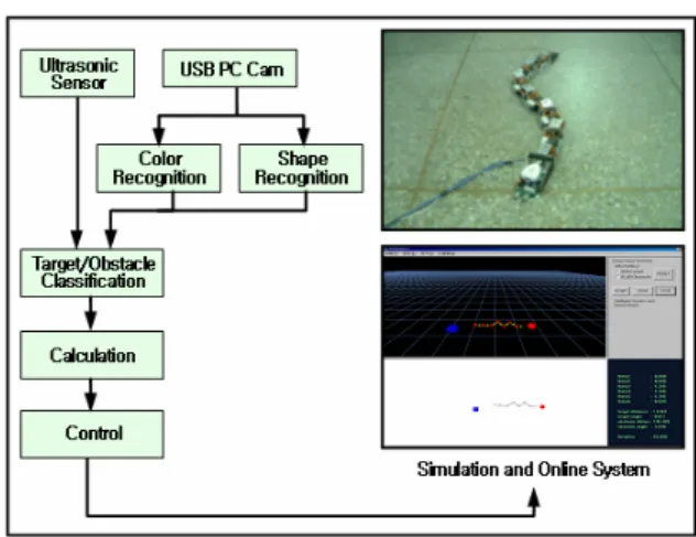
Snake robot divides target of red and obstacle of blue through utilization of USB PC Camera and it acquires the distance information by ultrasonic sensor. The Color and the distance information uses to 2D and 3D simulation using computer and experiment to realize in the on-line system. Figure 8 is model for simulation and online system.
Fig. 8 Model for simulation and online systme. 4.1 Algorithm for collision avoidance
The snake robot can be used to noxious environment that person's access is difficult, the bottom of the sea and an exploration universe. To realize autonomous robot that have intelligence, we must study important skills for environment recognition, avoidance, mapping skill and planning path. In the paper we have studied the optimal planning path so that snake robot can avoid obstacle.
Fig. 9 Moving forward of the snake robot.
Figure 9 depicts moving forward of the snake robot to target of red color. The experiment used the distance and the
angle(+2.82480˚) between target and a head of snake robot. The snake robot advances to a target by basic motion that is proposed in the front. If obstacle of blue is near than target of red when snake robot is being an advance, snake robot calculates intermediately point and act a forward. Intermediately point determine by using distance value and angle value between a head of snake robot and obstacle of blue. Also it fixed range differently about input range and obstacle position. ) ( ) ( nce tely_dista Intermedia = γ2 + li2
(12)
ance dist obstacle range tput in li i = = ⎟⎟ ⎠ ⎞ ⎜⎜ ⎝ ⎛ = − γ γ θ , 50 tan 1 4.2 Simulation Fig. 13 Simulator(3D). Method that avoid obstacle was showed as picture under.Figure 10 and 11 is to do simulation about intermediately point setting by obstacle position and advanced direction of snake robot.
Also figure 14 and 15 is experience result that show movement route of robot about each obstacle position
Fig. 10 Collision avoidance algorithm(I).
Fig. 14 The result of simulation(I). Fig. 11 Collision avoidance algorithm(II).
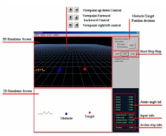
Simulator experimented about path selection of snake robot about obstacle position and it made to 2D and 3D. Figure 12 is 2D simulator and Figure 13 is 3D simulator.
Fig. 15 The result of simulation(II). Fig. 12 Simulator(2D).
5. CONCLUSION
In this paper we explained snake robot that is made as module type with imitation of biological snake. Motion of snake robot selected one sort of motions. Experience for collision avoidance and target arrival realized as simulator and we illustrated intelligent method. We could make a snake robot similar to a biological snake by structure of module type. We showed result about movement decision of snake robot that used intelligent method. Because algorithm that proposed in the front eliminated sensing ability of sensors, it showed superior ability in the simulation but it showed many difference against theory according to sensing ability if we execute collision avoidance algorithm in the online system. We will continuously have to research because system has problems that suitably compose them according to robot shape and control technique, a sort and angle of sensor and arrangement method. Also we will study motion of snake robot similar to a snake than present robot by use method of Side-Winding Motion instead of Concertina Motion.
ACKNOWLEDGMENTS
This research was supported by Wearable Intelligent & Interactive Module Development Program under Ministry of Commerce, Industry and Energy
REFERENCES
[1] J. Gray and H. Lissmann, “The Kinemetics of locomotion of the grass-snake,” J. Exp. Biol., vol. 26, pp. 354-367, 1950.
[2] H. Lissmann, “Rectilinear locomotion in a snake (Boa occidentalis),” J. Exp. Biol., vol. 26, pp. 368-379, 1950. [3] B.C. Jayne, “Kinemetics of terrestrial snake
locomotion,” Copeia, vol. 4, pp. 915-927, 1986.
[4] Craig, J. J., Introduction to Robotics: Mechanics and Control, Addison-Wesley, 1988.
[5] B.C.Jayne, and J.D. Davis, “Kinematics and performance capacity for the concertina locomotion of snake (Coluber constrictor),” J. Exp. Biol., Vol. 156, pp. 539-556, 1991. [6] Y. Shan, Obstacle accommodation: Mechanics, control,
and applications, Univ. Mich., Ann Arbor, 1992. [7] B.C Jayne, “Muscular mechanisms of snake locomotion:
An electromyographic study of the sidewinding and concertina modes of Crotalus cerastes, Nerodia fasciata and Elaphe obsoleta,” J. Exp. Biol., Vol. 140, pp. 1-33, 1988.
[8] S. Hirose, Biologically Inspired Robots: Snake-Like Locomotors and Manipulators. New York: Oxford Iniv. Press, 1993.
[9] W. Nelson and I. Cox, “Local Path Control for a Autonomous Vehicle,” Proc. IEEE Conf. on Robotics and Automation, 1504-1510, 1988.
![Figure 5 is a system of coordinates for each link of snake robot[8][9]. A head and a tail belong to link 7 and link 1](https://thumb-ap.123doks.com/thumbv2/123dokinfo/4891559.37086/3.892.95.419.488.689/figure-coordinates-link-snake-robot-head-tail-belong.webp)