1. INTRODUCTION
LonWorks network developed from Echelon Co. is a complete system that incorporates a communication standard with ANSI/EIA 709.1[1-2]. It also includes management and control. LonWorks technology has become so prevalent in building and process control systems that it has open, multi-vendor control systems. Use of the LonWorks technology significantly improves the easiness of network design and installation for the distributed control system. The LonWorks technology, now available as an open standard to all manufactures, however, is the platform that is driving the same sweeping changes in control system architectures displacing proprietary centralized systems with open, highly distributed, interoperable systems. Therefore, it is very important to connect LonWorks network to any existing microprocessor which is used widely in the industrial fields. We utilize the ShortStack to add the widely used microprocessor to LonWorks networks, which is provided freely from Echelon Co. We also describe how to develop an application for a LonWorks device using Echelon's ShortStack 2 Micro Sever. A ShortStack Micro Server consists of a Neuron Chip and transceiver, or an Echelon Smart Transceiver, running the ShortStack firmware. The ShortStack firmware for power line, free topology, and link power designs is included with ShortStack developer’s Kit [3]. The ShortStack Micro Sever provides a simple way to add LonWorks networking to
new or existing smart devices. It implements the LonTalk protocol and provides the physical interface with the LonWorks communication. The ShortStack host processor can be an 8, 16, or 32-bit microprocessor or microcontrollers. The ShortStack API and driver typically require about 4kbytes of program memory on the host processor and less than 200 bytes of RAM. The 4Kbyte program memory can be ROM, PROM, or flash. The ShortStack firmware requires a Smart Transceiver or Neuron Chip with minimum of 4Kbytes of application memory and 2Kbytes of RAM[3,4].
The interface between host processor and the ShortStack Micro Server may be a Serial Communication Interface (SCI). The LonWorks control module with a high performance is developed, which is composed of the 8 bit PIC Microprocessor for host processor and the smart neuron chip for the ShortStack Micro Server. This intelligent control board is verified as proceeding the various function tests from experimental system with an boost pump and inverter driving systems. It is also confirmed that the developed control module provides stably 0-10VDC linear signal to the input signal of inverter driving system for varying the induction motor speed. Thus, the experimental results show that the fabricating intelligent board carried out very well the various functions in the wide operating ranges of boost pump system. This developed control module expect to apply to industrial fields to require the comparatively exact control and monitoring such as multi-motor driving system with inverter, variable air volume system and the boost pump water supply systems[5,6].
Development of High Performance LonWorks Based Control Modules for Network-based Induction Motor
Control
Jung Gon Kim, Won –Pyo Hong*, Byeong Ju Yun**, Dong-Hwa Kim***
Maintenance section ,Hyundae Elevator Co, Daejeon, Korea(Tel: +82-42- 1065: E-mail:
[email protected])*Department of building Services Engineering,
Hanbat National University, Deajeon, Korea(Tel : +82-42-821-1179; E-mail: [email protected]) ** R & D Institute , Vitzros Co., Ltd.Seoul Korea (Tel : +81-2-460-2090; E-mail: [email protected])
***Department of Control Engineering, , Hanbat National University, Deajeon, Korea (Tel : +81-42-821-1170; E-mail: [email protected])
Abstract:
The ShortStack Micro Server enables any product that contains a microcontroller or microprocessor to quickly and inexpensively become a networked, Internet-accessible device. The ShortStack Micro Server provides a simple way to add LonWorks networking to new or existing smart devices. . It implements the LonTalk protocol and provides the physical interface with the LonWorks communication. The ShortStack host processor can be an 8, 16, or 32-bit microprocessor or microcontrollers. The ShortStack API and driver typically require about 4kbytes of program memory on the host processor and less than 200 bytes of RAM. The interface between host processor and the ShortStack Micro Server may be a Serial Communication Interface (SCI). The LonWorks control module with a high performance is developed, which is composed of the 8 bit PIC Microprocessor for host processor and the smart neuron chip for the ShortStack Micro Server. This intelligent control board is verified as proceeding the various function tests from experimental system with an boost pump and inverter driving systems. It is also confirmed that the developed control module provides stably 0-10VDC linear signal to the input signal of inverter driving system for varying the induction motor speed. Thus, the experimental results show that the fabricating intelligent board carried out very well the various functions in the wide operating ranges of boost pump system. This developed control module expect to apply to industrial fields to require the comparatively exact control and monitoring such as multi-motor driving system with inverter, variable air volume system and the boost pump water supply systems.
2. LonWorks Network and PIC Microprocessor
The section of microprocessors is governed by various factors, being mainly dependent on the nature of the applications to be addressed. Among field-bus systems and control networks on the market. LonWorks offers perhaps the most powerful features in term of architecture, communication flexibility and network management. LonWorks is chosen for the research study largely to take advantage of its architectural features, flexibility and its comprehensive range of development tools. The case study is based on the use of Neuron chips which are sophisticated VLSI devices that make it possible to implement low-cost local operating networks applications.2.1. Intelligent LonWorks node[3]
LonWorks from Echelon is a complete system that incorporates a communication standard with ANSI/EIA 709.1. It also includes management and control. The neuron chip contains three eight-bit processors. The application processor is executing user code written in a variant of Neuron C language with powerful input/output functions. A network processor handles addressing, routing, authentication of packets and the presentation of data to the application processor. The MAC processor is responsible for encoding I/O, importing measurement, calculating, calibration and transmission of packets of data to the network. Most of intelligent functions are implemented by embedded neuron networks stored in EEPROM. These two processors comply with six layers of the ISO reference model. This allows the transparent use of the network to pass information between the different programs in the application processors.
• Simplified interface module design
There are 34 different I/O objects available within a Neuron chip. Various I/O objects may be used simultaneously if desired. With this provision, the interface circuit between the controller and the physical devices can be greatly simplified, reducing the size and the costs of the devices and offering enhanced reliability.
•Three dedicated CPUs and built-in firmware
Three CPUs are employed on a Neuron chip, with two of them handling the layers one to six which conform to the seven-layer network protocol stack, i.e. driving the communications subsystem hardware, executing the collision avoidance algorithm, network variable processing, addressing, transaction processing, authentication, background diagnostics, software timer, network management, and routing functions, This enables the development effort to focus on application programming, instead of spreading a considerable amount of time in dealing with the communications protocol and communication interface circuit. The firmware embedded in the Neuron chip contains communication protocol, an operating system and data I/O applications library. This simplifies applications programming as the data I/O communication and I/O devices are automatically handled through a library call.
•Multi communication medium and communication data rates
Neuron chip based on LonWorks supports multi-communication medium, such as; twist pair cable, coaxial cable, power line, radio frequency, infrared and optical fiber. It also supports a wide range communications data rates from 4.9-1250Kbit/s. The versatility in communication medium and data rates in fact a unique feature among fieldbus systems and control networks currently available on the market.
•High level programming language
Neuron C is a programming language designed for Neuron chips and is based on the ANSI C language. It includes extension to ANSI C that directly supports the Neuron chip firmware, which make it a power tool for the development of LonWorks application. The use of high level programming languages is a desirable feature now offered by controller developer and suppliers. This can be seen as a move towards code portability and self-documentation. The dependency of software code on a particular processor or platform is seen as a stumbling block for developers from quickly adapting to the use of the latest and most appropriate processing platforms.
• Exploitation of network variables
Using the Neuron chip as the controller of the intelligent devices you can use Standard Network Variable Types (SNVTs). SNVTs provide a data-oriented application protocol. Application data items such as speed, length, states, text strings, and other data items are exchanged between devices in standard engineering and other defined units. Commands are encapsulated within the application programs of the receiver devices rather than being sent over the network. In this way, the same engineering value can be sent to multiple devices even though each device has a different application program for the data item. SNVTs facilitates interoperability by providing a well-defined interface for communication between nodes made by different manufactures, A node may be installed in a network and logically connected to other nodes via network variables as long as the data types match. Comparing network variables with commands and using network variables rather than commands will result in smaller application programs, implicit buffer allocation/freeing and optimizing communication services at installation rather than during application development. A developer does not then have to concern himself with how and where the devices will be connected and the communication with other devices is established.
• ID of the devices
A unique 48-bit ID is assigned with each Neuron chip when manufactured. The 48 bit ID may be read and used by application programs as a unique product serial number. It can also be used as a network address during installation and
configuration.
2.2 PIC Microprocessor [8,9]
This powerful (200 nanosecond instruction execution) yet easy-to-program (only 35 single word instructions) CMOS FLASH-based 8-bit microcontroller packs Microchip's powerful PIC® architecture into a 40- or 44-pin package.
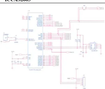
PIC16F877 features 256 bytes of EEPROM data memory, self programming, an ICD, 8 channels of 10-bit Analog-to-Digital (A/D) converter, 2 additional timers, 2 capture/compare/PWM functions, the synchronous serial port can be configured as either 3-wire Serial Peripheral Interface (SPI™) or the 2-wire Inter-Integrated Circuit (I²C™) bus and a Universal Asynchronous Receiver Transmitter (USART). All of these features make it ideal for more advanced level A/D applications in automotive, industrial, appliances and consumer applications. PIC16F877 8 bit microcontroller is selected to the host processor because of simple programming and general purpose. Fig. 3 shows a designed PIC circuits to use to the host processor.
Fig.3 PICF877 circuits of host processor
3. ARCHITECTURE OF SHORTSTACK
The ShortStack device consists of the following components:1) ShortStack Micro Server running the ShortStack firmware 2) SCI or SPI serial driver for the host processor
3) ShortStack API for the host processor
4) ShortStack application using the ShortStack API
Figure 1 below illustrates the software architecture of a ShortStack device.
Fig. 1 ShortStack architecture
2.1 ShortStack Micro Server
A ShortStack Micro Server consists of ShortStack firmware running in an Echelon Smart Transceiver, or running in a Neuron Chip with a separate LonWorks transceiver. The ShortStack Micro Server implements layers 1-6 layers of LonTalk protocol. A ShortStack can be created by loading a ShortStack firmware image in an Echelon Smart Transceiver, Neuron Chip, or control module. The ShortStack Micro Server communicate with host processor using either a serial communication Interface (SCI) or a Serial Peripheral Interface (SPI). The ShortStack SCI interface is a half-duplex asynchronous serial interface with 1 start bit, 8 data bits, and 1
stop bit.
You can program the ShortStack firmware into Atmel flash memory device that you can use with an Echelon FT 3150 Smart Transceiver or a Neuron 3150 Chip. The ShortStack3150_v2.nei file in the LonWorks ShortStack/Micro Servers folder holds the image for such a flash memory device. You can load the ShortStack firmware in the flash memory device using a third-party PROM programmer.
2.2 ShortStack Serial driver
The ShortStack serial driver provides a hard-independent interface between ShortStack API and ShortStack Micro Sever. It manages data exchange between your host ant the ShortStack Micro Server. You must create the serial driver that resides on your host microprocessor. The driver needs to exchange link layer messages with ShortStack Micro Server. The link layer header consists of two parts: the length byte and the network interface command byte. Following the link-layer header is the message payload
The ShortStack API uses several functions to transmit and receive message to and from the ShortStack serial driver. These functions are declared in the ShortStack API files. The ShortStack serial driver is required to support these functions. 2.3 SCI Interface
A ShortStack Micro Server has 11 pins that control the configuration of Micro Server and provide the interface to the host. We choose SCI interface because it is typically faster and easier to implement, both in hardware and software.
An SCI interface is selected by setting the ShortStack IO3 input to 0. The speed of the interface depends on whether SCI or SPI is used, and the clock speed of the ShortStack Micro Server. SCI serial bit rates is 9600 bps because of the clock rate of Neuron chip with 10MHz and IO5 and IO6 with VDD. Figure 2 shows the SCI communication interface. In an SCI uplink operation, data is transferred from the ShortStack Micro Server to the host processor. In the other hand, data is transferred from the host processor to the ShortStack Micro Server in an SCI downlink operation. To send a message downlink the driver needs to initiate two downlink operation: one for the link layer message header and the other for the message payload. The driver first initiates the transfer of the link-layer message header, then, if allowed, transfers the link-layer message header. Next, the driver initiates the transfer of the message payload, then, if allowed, transfers the message payload.
3. DEVELOPMENT PROCESS
The development process for creating a ShortStack device is described as the following sequences.
• Build a ShortStack Micro Server by loading a Smart Transceiver, Neuron Chip, or control module with the ShortStack firmware
• Integrate the ShortStack Micro Server with PICF877 host processor.
• Create the serial driver to reside on the host processor. •Use the Nodebuilder Resource Editor and the SNVT and SCPT Master list to select and define the functional profiles and resource types for host processor.
A Neuron C model file is used to define the inputs and outputs for the ShortStack application. The Neuron C model file describes the set and attributes of the functional blocks, network variables, and configuration properties that make up the interface for a ShortStack device. The NodeBuilder Code Wizard is used to automatically create a Neuron C model file. This can save you a great deal of work over manually creating a Neuron C model file. Using the NodeBuilder Code Wizard, you can define your device interface by dragging functional profiles and type definition from a graphical view of the resource catalog to a graphical view of the device interface. When you have completed the device interface definition, click the Generate Code and Exit button to automatically generate the Neuron C model file.
– Defining the device interface
A Neuron C model file is used to define the device interface for the host microprocessor. The device interface for a LonWorks device consists of its functional blocks, network variables, and configuration properties. Functional profiles, network variables types, and configuration property types are defined in resource files. LonWorks resource files use a standard format that is recognized by all interoperable network tools such as the LonMaker Integration Tool.
– Declaring a functional block
A functional block in a Neuron C model file can be declared. A functional block must be defined by a standard or user functional profiles within a resource file as described in the pervious paragraph. A functional block declaration does not cause the ShortStack Wizard to generate any executable code, though the wizard does create some data structures that are used to accomplish various functional block features.
– A network variable in a Neuron C model file can be declared. A ShortStack application can declare a maximum of 62 network variables. The syntax for a single network variable object and an array of network variable are declared.
– Declaring a configuration property
A configuration property using one of two different technique can be implemented. The first, called a
configuration network variable, uses a network variable to
implement the configuration property. This ha the advantage of enabling the configuration property to be modified by another LonWorks device, just like any other network variable. The second method of implementing configuration properties uses configuration files to implement the configuration property for a device. Rather than being separate externally-exposed data items, all configuration properties implement within configuration files are combined into one or two blocks of data called value files A value file consists if configuration property records of varying length concatenated together. Each value file must fit as contiguous bytes into the memory space in the device that is accessible by the application.
–Instantiating a configuration property
As discussed above, the cp_famaly declaration is similar to a C language typedef because no actual variable are creared as a result of the declaration. In the case of a type definition, variables are instantiated when the type definition used in a later declaration that is not, itself, another typedef. At that time, variables are instantiated, which means that variables are are declared and memory is allocated for and assigned to the variables. The variables can then be used in later expressions in the executable code of the program. The instantiation of CP family members occurs when the CP family declaration’s identifier is used in property list.
– Declaring a message tag
A message tag is a connection point for application messages. Application messages are used for 속 LONWORKS transfer protocol, and are also used to implement proprietary interface to LonWorks devices.
– Using authentication
Authentication is a special form of an acknowledged service between one writer device and from 1 to 63 reader devices. Authentication is used by the reader devices to verify the identity of the writer device.
• Structure the layout and interoperable interface of the ShortStack device by creating a Neuron C model file.
• Use the ShortStack Wizard to generate device interface data and a device interface file
The ShortStack Wizard makes the process easy by generating the device interface data required to implement the device interface. It also generates a device interface file that is used by a network tool when designing a network that uses the device.
• Port the ShortStack API to the host processor
Most ShortStack applications need to perform only six tasks: persistent storage, initialization, calling the event handler, sending and receiving network variables, and handling network management commands.
• Complete the ShortStack API callback functions to handle application-specific LonWorks events.
• Modify the ShortStack application to interface with a LonWorks network by using the ShortStack API function calls.
• Install and integrate the ShortStack device using a LonWorks network tool such as the LonMaker Integration Tool.
4. EXPERIMENTAL RESULTS AND
DISCUSSIONS
4.1 Implementation method of ShortStack system
• ShortStack3150.net is downloaded to the ShortStack Micro Server. In this study, we download ShortStack3150.net from AT29c512. Fig 3 shows the ShortStack board included the ShortStack Micro Server and the host microprocessor, PIC16F877 CMOS FLASH-based 8-bit microcontroller packs Microchip's powerful PIC® architecture into a 40- or 44-pin package.
• A ShortStack Micro Server consists of ShortStack firmware running in an Echelon Smart Transceiver, or running in a Neuron Chip with a separate LonWorks transceiver. The ShortStack Micro Server implements layers 1-6 layers of LonTalk protocol. A ShortStack can be created by loading a ShortStack firmware image in an Echelon Smart Transceiver, Neuron Chip, or control module. The ShortStack Micro Server communicate with host processor using either a serial communication Interface (SCI) or a Serial Peripheral Interface (SPI). The ShortStack SCI interface is a half-duplex asynchronous serial interface with 1 start bit, 8 data bits, and 1
Fig.3 Developed ShortStack board
stop bit. We could program the ShortStack firmware into Atmel flash memory device that you can use with an Echelon FT 3150 Smart Transceiver or a Neuron 3150 Chip. The ShortStack3150_v2.nei file in the LonWorks ShortStack/Micro Servers folder holds the image for such a flash memory device. You can load the ShortStack firmware in the flash memory device using a third-party PROM programmer. We choose SCI interface because it is typically faster and easier to implement, both in hardware and software
• A Neuron C model file is used to define the inputs and outputs for the ShortStack application. The Neuron C model file describes the set and attributes of the functional blocks, network variables, and configuration properties that make up the interface for a ShortStack device. The NodeBuilder Code Wizard is used to automatically create a Neuron C model file. This can save you a great deal of work over manually creating a Neuron C model file. Using the NodeBuilder Code Wizard, you can define your device interface by dragging functional profiles and type definition from a graphical view of the resource catalog to a graphical view of the device interface. When the device interface definition has been completed, click the Generate Code and Exit button to automatically generate the Neuron C model file.
• Using ShortStack Wizard, the interface data and device interface files is generated. The ShortStack Wizard creates the table of all network variables and then initializes ShortStack Micro Server. It also automatically generates the needed codes. In the case of configuration property, Direct memory read/write is not supported.
When the ShortStack Wizard is driving, the five files is created as following:
– platform.h: Platform dependent flags, basic data type – NvTypes.h: structure and enumerations of network variables
– LonDevice.h & LonDevice.h: NV definition and utility functions
– filedir.h: structure of FTP transaction
• After event application of LonWorks is modified and supplemented for using in the ShortStack device, it is complied by Hi-Teck compiler and then is completed the burning works.
• The ShortStack device is tested by the LonMaker for Windows
• Finally, the Device Plug-In is developed.
4.2 Implementation of Experimental equipment for ShortStack system
Fig. 4 shows the view of experimental equipment for performing the developed ShortStack devices. This consist of the ShortStack board that the ShortStack Micro Server and host processor included, an inverter system for vector controller, and pump system drived to induction motor at 2.2kW. LonMaker for Windows is used to monitor the experimental system. Fig. 5 shows the software configuration diagram of the experimental system. It is included the network configuration and the diagram results of the binding network variables of function blocks represented the installed devices.
Fig. 4 Experimental test bed for ShortStack device
Fig 5 Software configuration diagram of the experimental system
Fig. 6 shows the data of input and output network variables of function blocks by the LonMaker for Windows. It represents that the developed ShortStack device has a good performance in operating the boosted pump system.
Fig. 6 Data of input and output network variables of function blocks
4.3 Experimental results
• Host microprocessor PIC 16F877 has the 10bit A/D converter. It can convert the pressure sensor signal (0-5V)to the digital signal.
• The low and high limit value is set by key pad or the LonMaker for Windows. The digital signal within the low limit and high limit value is converted to the analog signal value (0-10V). This value is added to the input of inverter system for regulating the speed of induction motor and then commands the speed of induction motor.
• If the pressure is near to the low limit value, the revolution of pump system becomes higher. In the other hand, if the pressure installed in the exiting pipe of pump is near to the high limit value, the revolution of pump system become lower. • To confirm the performance of the ShortStack device, we use the oscilloscope and LCD display to measure the inverter input value. It is certain that the input variation according to the change of the detection value of pressure sensor is very sensitive and linear. When pressure sensing value has the high limit, Fig 7(a) shows that inverter input signal is 0. Also, when the pressure sensing value has the lower limit, Fig, 7(b) represents the inverter input signal is 10V. Table 1 represents the experimental results of linear variation of motor speed according to the pressure sensing value. We verify that the ShortStack device provides the linear value to the inverter input according to the change of pressure sensing value over the full range from the low limit to high limit value.
(a) Inverter input value 0V
(b) Inverter input value 10V
Fig, 7 Inverter input value according to pressure sensing value
Table 1 Inverter input value and motor speed versus
pressure sensing value
Setting high limit Setting low limit Inverter input value output value(V) Motor speed (rpm) 1000 200 1004 0 0 1000 200 807 2.5 425 1000 200 602 5 850 1000 200 405 7.5 1275 1000 200 194 10 1700
5. Conclusions
The LonWorks control module with a high performance is developed, which is composed of the 8 bit PIC16F877 microprocessor as a host processor and the smart neuron chip for the ShortStack Micro Server. This intelligent control board is verified as proceeding the various function tests from experimental system with a boost pump and inverter driving systems. It is also confirmed that the developed control module provides stably 0-10VDC linear signal to the input signal of inverter driving system for varying the induction motor speed. Thus, the experimental results show that the fabricating intelligent board carried out very well the various functions in the wide operating ranges of boost pump system. This developed control module expect to apply to industrial fields to require the comparatively exact control and monitoring such as multi-motor driving system with inverter, variable air volume system and the boost pump water supply systems.
In near future, a development of application algorithm for the general purpose microprocessor chip will be carried out to apply adaptively in the various industrial field. Also, we plan to study for developing the accurate ShortStack device including feedback loop to regulate motor speed in the networked multi-motor system.
ACKNOWLEDGMENTS
The authors would like to gratefully acknowledge the financial support of KESRI (Korea Electrical Engineering & Science Research Institute) and also ETPT of KEPRI under the project number A3050.
REFERENCES
[1] W.P. Hong," Implementation of Internet Based Control by Developing LonWorks Intelligent Control Modules," ICCAS 2001, Oct. 17-21, Cheju National Univ., Jeju Island, Korea, 2001.
[2] W.P. Hong, “A Novel Design of Intelligent Fire Alarm Signaling System for the integration of BAS by Developing Intelligent I/O Control Modules with LonTalk Protocol”, The International Conference on Electrical Engineering(ICEE 2002), Korea, July 7-11, 2002.
[3] Echelon, "ShortStack User's Guide", 2002.
[4] D. Loy, "Open Control Networks", Kluwer Academic Publishers, pp.217-229, 2001.
[5] Won-Pyo Hong, “Networked Intelligent Motor-Control Systems Using IEEE/EIA 709.1 Fieldbus," International Symposium on Computational Intelligence and Industrial Applications (ISCIIA2004), DEC.20-24, Hainan Univ., Haikou, China, 2004
[6]Won-Pyo Hong, “ Internet-Based Control and Monitoring System Using LonWorks Fieldbus for HVAC Application,” ICCAS2004, August25-27, Bangkok, Thailand, pp1205-1210, 2004.
[7] Echelon Co, "LonMaker for Windows User's Guide", 2003.
[8] Microchip, "16F877 Data Sheet", 2003.
[9] Microchip, "HI_TECH_PICC piclite User's Guide" [10] Echelon, "LonBuilder User's Guide", 1999. [11] Echelon, "Neuron C Programmer's Guide", 2001. [12] Echelon, "Neuron C Reference Guide", 2001. [13] Echelon, "NodeBuilder User's Guide", 2001.