ICCAS2005 June 2-5, KINTEX, Gyeonggi-Do, Korea
Force Control of Hybrid Actuator using
Learning Vector Quantization Neural Network
Kyoung Kwan AHN
*, and NGUYEN Huynh Thai Chau
** *School of Mechanical and Automotive Engineering, University of Ulsan,San 29, Muger 2dong, Nam-gu, Ulsan 680-749, Korea
**Graduate School of Mechanical and Automotive Engineering, University of Ulsan, San 29, Muger 2dong, Nam-gu, Ulsan 680-749, Korea
Abstract: Hydraulic actuators are important in modern industry due to high power, fast response, and high stiffness. In recent years, hybrid actuation system, which combines electric and hydraulic technology in a compact unit, can be adapted to a wide variety of force, speed and torque requirements. Moreover, the hybrid actuation system has dealt with the energy consumption and noise problem existed in the conventional hydraulic system. Therefore, hybrid actuator has a wide range of application fields such as plastic injection-molding and metal forming technology, where force or pressure control is the most important technology. In this paper, the solution for force control of hybrid system is presented. However, some limitations still exist such as deterioration of the performance of transient response due to the variable environment stiffness. Therefore, intelligent switching control using Learning Vector Quantization Neural Network (LVQNN) is newly proposed in this paper in order to overcome these limitations. Experiments are carried out to evaluate the effectiveness of the proposed algorithm with large variation of stiffness of external environment. In addition, it is understood that the new system has energy saving effect even though it has almost the same response as that of valve controlled system.
Keywords: Hybrid Actuator, Hydraulic System, Neural Network, Intelligent Control, Switching Control, Force Control.
1. INTRODUCTION
Nowadays, hydraulic systems play an important role in the industrial field. Hydraulic technology has been developed rapidly to enhance their performance parameters such as accurate speed control, high power weight ratios, physical size, controllability, reliability, cost and so on. Recently, energy consumption and the level of noise have become an important factor to evaluate the performance of machines and equipment. However, the previous hydraulic actuators are controlled completely by valve, thus a lot of energy was wasted to heat due to throttle losses at the control valves. Moreover, these models are difficult to apply for mobile machines because of complication of components. To overcome these weak points in a conventional system and to satisfy new requirements, a new concept of hydraulic actuator, which is called as hybrid actuator, is proposed.
The joint integrated rotary servo actuator, so-called hybrid actuator system, is known as the powershift system, which shifts from the high speed electric to high force hydraulic, thus creating the sleeker, the cleaner and more energy efficient way to produce high force. Besides, the new design is highly suitable for end-effector joints especially in robot technology. These energy saving features of hybrid actuator were proved clearly by Robert Rahmfeld and Monika Ivantysynova [14]. They developed a precise mathematical model describing the losses of hybrid actuator including servo pump losses, cylinder losses and pressure losses in hydraulic lines. In addition, the comparison between conventional actuator and hybrid actuator in the load-sensing system was also presented on that paper.
Hybrid actuator has a wide range of application fields such as plastic injection-molding and metal forming technology especially in aeronautics [3], where force or pressure control is most important technology. Therefore, the control of force or position of hybrid system should be of great interest. In particular, force tracking is important for some applications, because the actuators need to make contact with environment during the execution of their tasks. In recent years, various
force control strategies have been proposed in conventional hydraulic system, such as robust control [11-13][15], neural network control [10], optimal control based on the Lyapunov function [7], fuzzy switching control [9] and so on. However, hybrid actuator is new and there are little application examples using this actuator. Jörg Grabbel [8] presented two different control strategies in order to control position/velocity of hybrid actuator, and succeeded in overcoming the low damping ratio problem but the result was not good if the load changes. To show the tradeoff of hydraulic servo system and hybrid system, Johan Andersson and his colleague [4-6] used multi-objective genetic algorithm to optimize these system and elucidate the advantages of different concepts based on optimization results and sensitive analysis.
The objective of this paper is to introduce the new energy-saving and low noise hybrid actuator and to develop force control strategy. Furthermore, the intelligent switching control algorithm by LVQNN [1-2] is newly proposed in order to overcome these limitations such as low damping and deteriorations of the performance of transient response due to the change of environment stiffness. Experiments were carried out to evaluate the effectiveness of the proposed algorithm.
The rest of this paper is organized as follows: In section 2, the model of hybrid system used in this study is described. In section 3, the detailed control algorithm of the proposed method is described and section 4 shows the experimental procedure and results. Finally, some conclusions are made in section 5.
2. EXPERIMENT SETUP
The schematic diagram of the hybrid system is shown in Fig. 1. The system hardware consists of an IBM compatible personal computer (Pentium 1GHz), which is used to get the feedback signal through A/D board (Advantech, PCI 1711), and calculates control input, a hydraulic pump, AC servo motor (OTIS-LG, FMA-LN09-AB00), and a pressure sensor (SETech, PMSA010QKAAA) used to measure the pressure at
one chamber. The force is measured using the load cell (SETech, YC 60-500K). The control input is converted to an analog signal by the D/A board (Advantech, PCI 1720). Springs with different stiffness are used to represent the environments.
In the field of fluid power control, the driving concept using hydraulic pump with variable rotational speed to control flow is a new approach. In the operation of hybrid system, the bidirectional rotational pump is driven by the AC servo motor so that the pump can supply pressured oil in a bidirection. The pump sucks in oil by supplying oil from the cylinder return line and by using the self-support valve to compensate for the excessive and deficient quantity of oil in the area difference of the cylinder. Because the hybrid system operates in the rotational angle and speed to satisfy the machine requirements such as pressure and flow rate, it provides energy savings and ensures lower noise generation than conventional systems.
Fig. 1 Schematic diagram of Hybrid System.
Fig. 2 Photograph of experimental apparatus
3. INTELLIGENT SWITCHING CONTROL
ALGORITHM
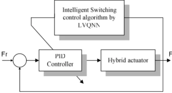
3.1 The overall control systemIn hybrid system, the position and speed of AC servo motor is controlled in order to adjust and supply pressure and flow rate of the hydraulic pump. Therefore, the performance of hybrid actuator depends on the control performance of AC servo motor. Low damping ratio, which is a weakness of hybrid system, had been solved by using PI controller where the integral action was necessary to compensate for control deviation in the velocity control loop [8]. However, the control performance could not be guaranteed if controller with fixed gain were used. Therefore, it is necessary to recognize the changing environment stiffness in order to switch to the suitable gain. Figure 3 show the overall structure of the proposed algorithm. Here, we used learning vector quantization neural network (LVQNN) as a classifier which classifies different stiffness environments (10, 30, 50kN/m).
Fig. 3 Structure of newly proposed control algorithm. To control force of hybrid system, the switching control strategy is applied where conventional PID control algorithm is used as the basic controller. The controller output can be expressed in the time domain as:
( )
( )
( )
( )
dt t de T K dt t e T K t e K t u p d t i p p + + =∫
0 (1) The Laplace transform of (1) is:( )
( )
E( )
s K TE( )
s s T K s E K s U p d i p p + + = (2)And the resulting PID transfer function is:
( )
( )
+ + = T s s T K s E s U d i p 1 1 (3)A typical real-time implementation at sampling sequence k can be expressed as:
( )
( )
( )
( ) (
)
T k e k e T K k e T T K k u k e K k u p d i p p 1 ) 1 ( − + + − − + = (4)where u(k), e(k) are control input to control velocity of AC servo motor and error between desired force set point and the output, respectively.
3.2 Recognition of environment stiffness by using LVQNN 3.2.1 Structure of Neural Classifier
There are some types of learning in neural network such as supervised, unsupervised and hybrid learning. Supervised learning is the training using desired response for given stimuli; unsupervised learning is classification by “clustering” of stimuli, without specified response; and hybrid is combination of the above. LVQNN combines competitive learning, which is a form of unsupervised learning but combinable with supervised learning, with supervision.
To classify the stiffness of environments which have nonlinearity characteristic, we use the neural network structure
as show in Fig. 4, where D represents Euclidean distance weight function as shown in the following equation:
( )
(
)
∑
(
( )
( )
)
= − = R i i W i P i W P D 1 2 1 1 , (5)W1: number of neurons of competitive layer.
C is a competitive transfer function, which return output vector with 1 where each net input vector has its maximum value, and 0 elsewhere. LVQNN consists of a hidden competitive layer and linear output layer. The principle of that is as following: first, competitive learning achieves clusters. Next, assign a class (or output value) to each cluster. Finally, reinforce cluster representative (a neuron) when it classifies input in the desired class. In the learning process, the weights of LVQNN are trained by the well-known Kohonen rule, which is show as the following equation:
( )
( )
(
( )
)
( )
( )
(
( )
)
= − − = = − + = + + y incorrectl classified is P if ..., , 2 , 1 , correctly classified is P if ..., , 2 , 1 , 1 1 1 1 1 1 1 1 1 1 S i i W P i W i W S i i W P i W i W t t t t t t α α (6)where αis learning ratio with positive and decreasing, . 1 n = α Fig. 4 Structure of LVQNN
The objective of LVQNN is to classify the stiffness of environments in an online manner. The structure of LVQNN input/output data is shown as Fig. 5, which consist of force, pressure and control input value as inputs, an integer value between 1 and 3 as output, which represents the stiffness of environment.(50, 30, 10 kN/m).
Fig. 5 Learning data for LVQNN 3.2.2 Training of the neural classifier
a) Acquisition of a training data
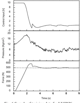
Generally, the more input vector we set the better recognition result we have. However, it takes more calculation time and makes the recognition time delay. In our experiment, the input vectors into LVQNN are set to be control input, contact force and pressure; the output of LVQNN is an integer value between 1 and 3, where class 1,2 and 3 mean that the stiffness of environment is approximately 50, 30, 10 kN/m, respectively. To obtain the learning data for LVQNN, a series
of experiments were conducted under 3 different stiffness springs, which simulate soft, medium and stiff environments. One sample of training data for LVQNN is shown in Fig. 6 which corresponds to class 2. In the generation of training data, the target force is set to be 500N and PID controller with fix gain was used.
b) Training process of LVQNN
The main feature of training the learning vector quantization neural network is to classify environment stiffness. Thus, determination of suitable input and number of neuron in the competitive layer in LVQNN are one of the essential issues in practical implementation of the neural
0 2 4 6 8 10 0 100 200 300 400 500 600 Time (s) F o rc e (N ) 0 4 8 12 16 20 P re s s u re (K g /c m 2) -2 0 2 4 6 8 10 C o n tro l In p u t [V ]
Fig. 6 Sample of training data for LVQNN
classifier. To determine the number of inputs, several training was performed by adjusting the number of inputs from 10 to 18, where the number of neuron of competitive layer is changed from 15 to 30. The training results (successful training rate [%]) for LVQNN are shown in table 1 and Fig. 7. From these results, we can see that the training result is almost satisfactory in the case of 22 neurons in competitive layer and 11 input data in the input layer with the learning success rate 82,33[%], which is enough to utilize in the recognition of environment stiffness.
Fig. 7 Learning success rate of the LVQNN
P(1) P(2) . . . . P(R) ( )2 1 W D D D
C
( )1 2 n ( )2 2 n ( )1 2S n∑
( )1 1 W ( )1 1S W∑
∑
( )1 1 a ( )2 1 a ( )3 1 a ( )1,1 2 W (2 1) 2S, S W y(1) y(2) . . . . y(n) ( )1 2 n ( )2 2 n ( )2 2S n ( )1 2 a ( )2 2 a ( )2 2S a P yTable 1. Learning success rate of LVQNN [%]. Inputs Neuron 10 11 13 16 18 30 78.89 78.72 78.78 80.9 79.10 28 78.48 78.67 79.08 79.28 78.30 26 79 81.54 79.24 79.22 78.20 24 79.1 81.52 78.68 78.63 78.84 22 79.17 82.33 79.38 78.23 78.56 20 79.01 82.19 79.14 78.56 78.67 18 78.69 81.4 78.62 79.08 78.56 15 79.63 78.51 78.82 79.22 78.82
Table 2. Optimal parameters of PID controller.
Class No. KP KI KD Class 1 (50kN/m) 0.04 1.10 -6 0.021 Class 2 (30kN/m) 0.05 2.10 -5 0.04 Class 3 (10kN/m) 0.07 1.10 -6 0.0722
3.2.3 Proposition of smooth switching algorithm
If the environment stiffness is between the stiffness of previous training condition, the output may belong to the mixed classes. Therefore, the following switching algorithm is proposed to apply for the abrupt change of class recognition result. The switching algorithm is described by the following equation:
( )
k class(
k) (
)
class( )
kclass =η× −1+1−η × (7)
where k is the discrete sequence, η is forgetting factor and
( )
kclass is the output of LVQNN at k time sequence. The optimal parameters of PID controller in accordance with environments stiffness are obtained by trial and error through experiments, which are shown in Table 2.
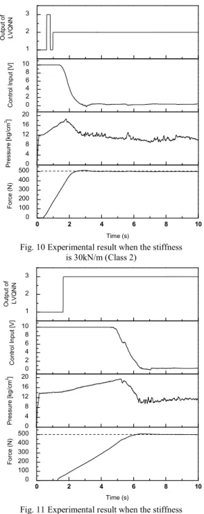
4. EXPERIMENTAL RESULTS
In this section, experiments were conducted to show the effectiveness of the proposed algorithm. Fig. 8 is the experimental result of the force response with different spring stiffness (10, 30, 50kN/m), where the control gains are fixed as the maximum environment stiffness. From Fig. 8, it is understood that the system response becomes more oscillatory and more overshoot when decreasing the stiffness of environment. Therefore, the control parameters must be adjusted according to the change of stiffness. Hence, the neural classifier LVQNN is necessary for recognition of the change of stiffness. The experimented results are shown in Fig. 9, 10 and 11, which corresponds to maximum stiffness (class 1), medium stiffness (class 2) and minimum stiffness (class 3), respectively. In control algorithm, the output of LVQNN starts to calculate when the cylinder contacted to the environment. From experiment results, it is verified that the environment stiffness was almost exactly recognized to the correct class and the tracking force response is realized with 5 [N] steady state errors.The comparison between 2 different stiffness environments (30, 10 [kN/m]) in case with and without using LVQNN are shown in Fig. 12 and 13. Through these experiments, we can see that the proposed algorithm is very effective in the accurate force control of hybrid system even if the environment is changed. 0 2 4 6 8 10 0 100 200 300 400 500 600 F o rce (N ) Time (s) Ref_Force (N) Stiffness 1 Stiffness 2 Stiffness 3
Fig. 8 Force response of hybrid actuator with conventional PID control (KP = 0.04; KI = 1.10-6; KD = 0.021) 0 2 4 6 8 10 0 100 200 300 400 500 Time (s) F o rc e ( N ) 0 4 8 12 16 P re s s u re [ k g /c m 2] 0 2 4 6 8 10 C o n tr o l In p u t [V ] 1 2 3 O u tp u t o f L V Q N N
Fig. 9 Experimental result when the stiffness is 50kN/m (Class 1)
5. CONCLUSIONS
In this study, a new energy saving hybrid actuator system that may be applied to a variety of industrial fields was developed. The force control was successfully implemented and the steady state error was reduced within 5 [N].
The second contribution of this paper is to propose a learning vector quantization neural network (LVQNN) as a supervisor of the switching controller in the hybrid actuator, where the LVQNN function to recognize the contacted environment stiffness and to select suitable gains for each environment.
From the experiments of the force control of hybrid actuator, it was verified that the smooth switching algorithm is very effective to overcome the deterioration of control
performances of transient responses even if the environment stiffness changed for 500 [%].
0 2 4 6 8 10 0 100 200 300 400 500 Time (s) F o rc e ( N ) 0 4 8 12 16 20 Pr e s s u re [ k g /c m 2] 0 2 4 6 8 10 C o n tr o l In p u t [V] 1 2 3 O u tp u t o f L VQ N N
Fig. 10 Experimental result when the stiffness is 30kN/m (Class 2) 0 2 4 6 8 10 0 100 200 300 400 500 Time (s) F o rc e ( N ) 0 4 8 12 16 20 P re s s u re [ k g /c m 2] 0 2 4 6 8 10 C o n tr o l In p u t [V ] 1 2 3 O u tp u t o f L V Q N N
Fig. 11 Experimental result when the stiffness is 10kN/m (Class 3) 0 2 4 6 8 10 0 100 200 300 400 500 600 F o rc e (N ) Time (s) Ref_Force (N) Without LVQNN With LVQNN
Fig. 12 Comparison between with and without using LVQNN when the stiffness is 30 kN/m.
0 2 4 6 8 10 0 100 200 300 400 500 600 F o rc e ( N ) Time (s) Ref_Force (N) Without LVQNN With LVQNN Fig. 13 Comparison between with and without using
LVQNN when the stiffness is 10 kN/m. ACKNOWLEDGMENTS
This work was supported (in part) by Ministry of Commerce, Industry and Energy (MOCIE) of Republic of Korea, through the Research Center for Machine Parts and Materials Processing (ReMM) at the University of Ulsan.
REFERENCES
[1] AHN, K. K., “Development of Force Reflecting Joystick for Hydraulic Excavator,” JSME Int. Journal, Series C, vol. 47, No. 3, pp. 858 ~ 863, 2004.
[2] AHN, K. K., Tu, D. C. T., “Improvement of the Control Performance of Pneumatic Artificial Manipulator using Intelligent Switching Control Method,” in KSME, Int. Journal, Vol. 18, No. 8, pp. 1388 ~ 1400, 2004.
[3] Andersson, J., Krus, P., Nilsson, K., “Optimization as a Support for Selection and Design of Aircraft Actuation Systems,” In Proc. of the Seventh AIAA/USAF/NASA/ISSMO Symposium on Multidisciplinary Analysis and Optimization, St. Louis, USA, September 2-4, 1998.
[4] Andersson J., “Sensitivity analysis in Pareto optimal design,” in Proc. of the 4th Asia-Pacific Conf. on Simulated Evolution and Learning, SEAL 02, Singapore, November 18-22, 2002.
[5] Andersson J., Krus P., Nilsson K., Storck, K., “Modelling and Simulation of Heat Generation in Electro-Hydrostatic Actuation Systems,” In proc. of the 4:th JHPS Int.
Symposium on Fluid Power, Tokyo, Japan, November 15-17, 1999.
[6] Andersson J., Krus P., Wallace D., “Multiobjective Optimization of Hydraulic Actuation Systems,” In Proc. of ASME Design Automation Conf., Baltimore, USA, September 11-13, 2000.
[7] Andrew Alleyne, Rui Liu, “A simplified approach to force control for electro-hydraulic systems,” Control Engineering Practice 8, pp. 1347-1356, 2000.
[8] Jörg Grabbel, “On the control of joint integrated servo actuators for mobile handling and robotic applications,” Proc. of 1st FPNI-PhD Symp. Hamburg, pp. 449-465,
2000.
[9] Ha, Q. P., Nguyen, Q. H., Rye, D. C., Durrant-Whyte, H. F., “Fuzzy Sliding-Mode Controllers with Applications,” IEEE Trans. on Industrial Electronics, vol. 48, No. 1, pp. 38 ~ 46, 2001.
[10] He, S., Sepehri, N., “Online Modeling and Prediction of a Hydraulic Force-acting System Using Neuron Networks,” IEEE Int., Conf., on Systems, Man, and Cybernetics, pp. 2667 ~ 2672, 2000.
[11] Hung-Ching Lu, Wen-Chen Lin, “Robust Controller with Disturbance Rejection for Hydraulic Servo Systems,” IEEE Trans. on Industrial Electronics, vol. 40, No. 1, pp. 157 ~ 162, 1993.
[12] Laurent Laval, Nacer K. M’Sirdi, Jean-Charles Cadiou, “
H
∞ Force Control of a Hydraulic Servo-Actuator with Environment Uncertainties,” Proc. of the 1996 IEEE International Conf. on Robotics and Automation, pp. 1566 ~ 1571, 1996.[13] Navid Niksefat, Nariman Sepehri, “Robust Force Controller Design for a Hydraulic Actuator Base on Experiment Input-Output data,” Proc. of the American Control Conf., San Diego, California, 1999.
[14] Rahmfeld, R., Ivantysynova, M., “Displacement Controlled Linear Actuator with Differential Cylinder - A Way to Save Primary Energy in Mobile Machines,” 5th Int., Conf., Fluid Power Transmission and Control (ICFP'2001), Hangzhou, China, S. 296-301, 2001. [15] Y. Yen, C. Lee, “Robust speed control of a pump control
motor system,” IEE Proc. – D, Vol.
![Fig. 8 Force response of hybrid actuator with conventional PID control (K P = 0.04; K I = 1.10 -6 ; K D = 0.021) 0 2 4 6 8 100100200300400500 Time (s)Force (N)0481216Pressure [kg/cm2]0246810Control Input [V]123Output ofLVQNN](https://thumb-ap.123doks.com/thumbv2/123dokinfo/4891323.37048/4.918.494.793.350.792/response-actuator-conventional-control-pressure-control-output-oflvqnn.webp)