1. INTRODUCTION
Disturbance observer (DOB) has been known to compensate effectively by observing it from the view point of linear system. After DOB was proposed by Ohnishi [1, 2], its design method and performance have been analyzed theoretically [3]. Recently the definition of disturbance has been expanded to modeling uncertainty including parameter variation, internal disturbance such as torque disturbance and friction. The purpose of using DOB is to enhance the performance of the system by observing and canceling such undesirable disturbances [4, 5]. In DOB, the disturbance rejection performance depends on Q-filter’s (low pass filter) order and its robustness against modeling uncertainty depends on relative degree and denominator order of Q-filter [6].
DOB is also applied to robot system, high speed system, precision position control, optical disk drive system [7]-[11]. Disturbances in optical disk drive system such as CD and DVD are composed of disk surface vibration, disk eccentricity and actuator resonance. In tracking servo, optical spot has to follow track with less than ±0.1 mµ tracking error. Thus the above mentioned disturbances cause it difficult to track follow such narrow track pitch in high speed and high density ODD system [11]. It is proposed that DOB is very effective in rejecting the disturbances in ODD system [10, 11]. However, only the tracking error is available in ODD system instead of reference input or output.
To overcome this problem, there were some attempts. One method is to use an additional sensor to estimate reference input and to apply the estimated reference input to DOB [10]. Another method is to apply an error based DOB (EDOB) which is a modified DOB [12] without using additional sensor to measure the reference input. Besides these methods, various types of DOBs, to improve disturbance rejection performance and sensitivity, were proposed for example PAC, RIC, MPEC and IMC. There has been a trial to reduce cross-coupling effect and improve sensitivity by adjusting gain between PAC (Passive Adaptive Controller) and DOB. RIC (Robust Internal
loop Compensator) can transform DOB to unity dc gain equivalent feedback with feed-forward. Its performance is determined by the bandwidth of Q-filter [9]. MPEC (Multi loop Perturbation Compensator) is another compensator design method with multi loop structure. Single loop DOB has a limitation for the compensation value of disturbance rejection due to time-delay and phase lag. We are able to get improved performance by adding additional external loop since the incomplete disturbance rejection in the inner loop can be compensated at the external loop DOB. This multi loop structure improves system robustness [13]. IMC (Internal Model Controller) compensates uncompensated disturbance of internal loop at external loop [14]. Although IMC improves sensitivity function by multiplying its external loop, it is very sensitive to measurement noise due to increase of complimentary sensitivity function peak.
The multi loop DOBs, which are proposed up to now, tend to bring poor transient response due to cross-coupling inter loops and phase lag [3]. Therefore, there need trade-off between sensitivity function in frequency domain and transient response in time domain. In this paper, Dual-DOB is proposed to maintain disturbance rejection performance of former multi loop DOB, reducing cross-coupling effect, and robust against measurement noise. The Dual-DOB structure consists of internal loop and external loop. Actually, it is similar to IMC structure however it has a different design method of external loop. Although IMC could improve disturbance rejection performance by adding its external loops, it is very sensitive to measurement noise due to the increased peak of complimentary sensitivity function. Therefore, in this paper to resolve this problem we use a different nominal model for designing the external loop DOBs. This is a major difference from IMC structure. As a result, the Dual-DOB proposed in this paper improves the sensitivity function at low frequency without increasing the peak of the sensitivity function. By designing DOB of internal and external loop independently, we could avoid degrading performance of transient response while improving the sensitivity function. The proposed
Optical Disk Drive Servo System Using Dual Disturbance Observer
Sang Han Lee*, Dong Seul Jeong
**and Chung Choo Chung
**** Department of Electronics and Computer Engineering, Hanyang University, Seoul 133-791, Korea (Tel : +82-2-2282-5307; E-mail: [email protected])
** Department of Electronics and Computer Engineering, Hanyang University, Seoul 133-791, Korea (Tel : +81-2-2282-5307; E-mail: [email protected])
*** Division of Electrical and Biomedical Engineering, Hanyang University, Seoul 133-791, Korea (Tel : +82-2-2220-1724; E-mail: [email protected])
Abstract: Using disturbance observer (DOB) is effective in enhancing the performance of dynamic system in the presence of
disturbances. Recently the definition of disturbance has been expanded to modeling uncertainty including parameter variation, internal disturbance. Various structures of DOB have been proposed to improve sensitivity of system for better disturbance rejection performance. However in the case of improvement of sensitivity function, it tends to bring poor transient response due to cross-coupling and phase lag. Furthermore it could be very sensitive to measurement noise due to increased peak of complementary sensitivity function. In this paper, a dual disturbance observer (Dual-DOB) is proposed to reduce the effect of such cross-coupling. It is possible for us to improve the sensitivity function with additional external DOB with hardly affecting complementary sensitivity function. Thus it is able to have robustness against measurement noise. Since we are able to design DOBs of internal and external loop independently, we could prevent transient response quality from degrading while improving the sensitivity function. The proposed Dual-DOB is applied to a commercial optical disk drive tracking servo system. The experimental result shows that the Dual-DOB is an effective method in rejecting the disturbance as well as improving the tracking performance.
Dual-DOB is applied to a tracking system of commercial optical disk drive. The experimental result shows that the Dual-DOB is an effective method in rejecting the disturbance as well as improving the tracking performance.
2. PRINCIPLE AND ANALYSIS OF
DISTURBANCE OBSERVER
2.1 Principle of Disturbance Observer
The DOB system rejects disturbance by injecting into the control input a compensation value, which is the difference between the commanded control input to the plant and the plant output filtered by the inverse of the nominal plantP sn( ),
i.e. 1
( ) n
P− s , as shown in Fig. 2. If unity dc gain Q-filter is used, the compensation value of DOB becomes idin low frequency bandwidth as in Eq. (1). Without consideration of uncertainty of plant modeling, the compensation value can completely reject torque disturbance in the input and output disturbance.
i
[
]
1 1 ( ) 1 1 lim ( ) ( ) . in n n out Q s in n out d u d P s P s u P d d P d − − → − = + − + ≅ +(1)
However, due to 1 ( ) nP− s generally contain pure differential term, often it is not physically realizable. Thus, it is common to use Q-filter with 1
( ) n
P− s . In addition using Q-filter reduces it less sensitive to measurement noise. This Q-filter has typically the characteristic of low pass filter (LPF) with a unity dc gain. In this paper, binomial Q-filter is used as a low pass filter [15].
( )
(
0 1)
,(
!)
! ! n i mi i mn m mi a s m Q a m i i s τ τ = = = − +∑
(2)
where
τ
is filter time-constant, ami are binomial coefficients,m
is the denominator order andn
is the numerator order of filter satisfyingm n
>
. The higher order of the filter is, the better performance of low pass filter can be obtained. However, high-order filter could have an adverse effect on controller performance due to phase lag. On the other hand, the bandwidth of Q-filter has also an effect on system response. As the bandwidth of Q-filter is increased, we can reject fast undesirable disturbance. Thus Q-filter is an important factor in the performance of DOB [6].2.2 Analysis of Applied Disturbance Observer System
It is not easy to analyze the performance of DOB through usual expansion of transfer function in the presence of modeling uncertainty even though we could analyze the performance of DOB from characteristic equation of transfer function. However, if we eliminate the real plant from the transfer function by using a new parameterδ( )s representing system uncertainty, it could be easy to manipulation equations and an intuitional analysis is further possible [3]. δ( )s is denoted as in Eq. (3) and there is a close affinity betweenδ( )s and ∆M( )s which is multiplicative modeling uncertainty. ( ) C s ( ) Q s ( ) P s 1 ( ) n ( ) Q s P− s + - + -- + + + n
r
y
in d dout + + + + i du
Fig. 1 System Structure of DOB.The real plant is defined as
[
]
( ) n( ) 1 M( ) P s =P s + ∆ s where ( ) ( ) ( ) ( ) n M n P s P s s P s − ∆ = .Then
δ
( )s is defined such that ( ) ( ) ( ) ( ) ( ) ( ) ( ) ( ) ( ) ( ) ( ) ( ) n M n n n n P s s s P s P s P s P s P s P s P s P s P s δ = ∆ ⋅− − − = ⋅ − =(3)
The total input-to-output relationship from the reference signal ( )r , the torque disturbance (din) , the output disturbance (dout), and the measurement noise ( )n to the
output are expressed in Eq. (4).
_ _ _
( ) ( ) ( ) ( )
Dob Dobin in Dobout out Dobnoise
y=G s r+S s d +S s d +T s n
(4)
where[
]
( ) ( ) ( ) ( ) 1 ( ) ( ) ( ) ( ) ( ) ( ) ( ) n Dob n n C s P s P s G s Q s P s Q s P s C s P s P s = − + +(5)
[
]
[
]
_ 1 ( ) ( ) ( ) ( ) 1 ( ) ( ) ( ) ( ) ( ) ( ) ( ) n Dob in n n Q s P s P s S s Q s P s Q s P s C s P s P s − = − + +(6)
[
]
[
]
_ 1 ( ) ( ) ( ) 1 ( ) ( ) ( ) ( ) ( ) ( ) ( ) n Dob out n n Q s P s S s Q s P s Q s P s C s P s P s − = − + +(7)
[
]
[
]
_ ( ) ( ) ( ) ( ) ( ) 1 ( ) ( ) ( ) ( ) ( ) ( ) ( ) n Dobnoise n n Q s C s P s P s T s Q s P s Q s P s C s P s P s − + = − + +(8)
For simplicity and intuitional analysis of Eqs. (5)~(8), we rewrite these as Eqs. (9)~(10) using parameter, δ( )s .
[
( )]
( ) ( ) ( ) 1 ( ) 1 ( ) ( ) n Dob n C s P s G s s Q s C s P s δ = − + +(9)
[
]
[
]
_ 1 ( ) ( ) ( ) ( ) 1 ( ) 1 ( ) ( ) n Dob in n Q s P s S s s Q s C s P s δ − = − + +(10)
[
][
]
[
]
_ 1 ( ) ( ) 1 ( ) ( ) 1 ( ) 1 ( ) ( ) Dob out n Q s s S s s Q s C s P s δ δ − + = − + +(11)
[
]
[
]
_ 1 ( ) 1 ( ) ( ) ( ) ( ) 1 ( ) 1 ( ) ( ) n Dob noise n Q s C s P s T s s Q s C s P s δ − − − = − + +(12)
If we assume that disturbance exists only in low frequency range in Eqs. (9)~(12), closed loop system acts like nominal
model system in low frequency due to Q-filter implement as low pass filter with a unity dc gain.
+ - + -- + + +
r
C s( ) P s( ) y 1 ( ) n ( ) Q s P− s ( ) Q s - + ( ) Q s + 1 ( ) DOB( ) Q s G− s -η in d dout + + + +Fig. 2 System Structure of Dual DOB
3. ANALYSIS OF DUAL-DOB STRUCTURE
3.1 Structure of Dual-DOB
Various structures of DOB have been proposed to improve sensitivity of system for better disturbance rejection performance [3, 9, 12, 14, 15]. Due to cross-coupling of multiple DOB structure, the performance of DOB needs trade-off between sensitivity of frequency domain and transient response of time domain. In this paper, the Dual-DOB is proposed to reduce the effect of cross-coupling. By designing DOB of internal and external loop independently, we could prevent the decreasing of transient response quality during improvement the sensitivity function. The Dual-DOB structure adds the external loop to the system including internal DOB loop as shown in Fig. 2. It is similar to IMC (Internal Model Controller) structure which is multiple DOB but Dual-DOB has different design method of external loop. Although IMC improves sensitivity function by multiplying its external loop, it is very sensitive to measurement noise due to increasing of complimentary sensitivity function peak [14]. Therefore we designed nominal system model used fro designing of external loop, differently from IMC structure in order to improve this problem.
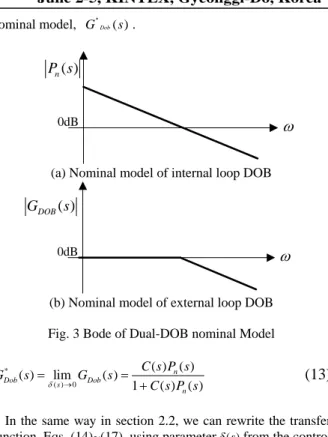
A conventional DOB system has a limitation of disturbance rejection performance due to time delay and modeling uncertainty. Internal loop of Dual-DOB uses a conventional DOB which uses a nominal model as shown in Fig. 3(a). To compensate disturbances uncompensated in the internal loop due to system modeling uncertainty and incomplete compensation, the external loop DOB use the desired closed loop transfer function as a nominal plant as Fig. 3(b). This is the key feature of the Dual-DOB proposed in this paper. Because the external DOB is designed based on nominal closed loop, it observes the behavior of the internal closed loop system including the internal DOB and compensates uncompensated disturbance. Thus we can get enhancement of sensitivity applying Dual-DOB structure. By designing Dual-DOB of internal and external loop independently, we could avoid degrading transient response performance while improving the sensitivity function in low frequency range.
3.2 Analysis of Dual-DOB System
Dual-DOB consists of internal DOB and external DOB. While internal DOB loop uses typical nominal model of plant as conventional DOB system, external loop DOB is designed by applying the desired closed loop transfer function Eq. (9) including internal DOB as a nominal plant. Due to the modeling uncertainty, we cannot use Eq. (9) as the transfer function. If we approximate Eq. (9) as Eq. (13) in low frequency range, however we could assume closed loop
nominal model, GDob( )s
∗ .
( )
nP s
0dBω
(a) Nominal model of internal loop DOB
( )
DOB
G
s
0dB
ω
(b) Nominal model of external loop DOB Fig. 3 Bode of Dual-DOB nominal Model
* ( ) 0 ( ) ( ) ( ) lim ( ) 1 ( ) ( ) n Dob Dob s n C s P s G s G s C s P s δ → = = +
(13)
In the same way in section 2.2, we can rewrite the transfer function, Eqs. (14)~(17), using parameterδ( )s from the control reference, the torque disturbance, the output disturbance, and the measurement noise to the output of the Dual-DOB system [3].
[
]
2 ( ) ( ) ( ) ( ) 1 ( ) 1 ( ) ( ) n Dual n C s P s G s s Q s C s P s δ = − + +(14)
[
]
[
]
2 _ 2 1 ( ) ( ) ( ) ( ) 1 ( ) 1 ( ) ( ) n Dual in n Q s P s S s s Q s C s P s δ − = − + +(15)
[
] [
]
[
]
2 _ 2 1 ( ) ( ) 1 ( ) ( ) 1 ( ) 1 ( ) ( ) Dual out n Q s s S s s Q s C s P s δ δ − + = − + +(16)
[
]
[
]
2 _ 2 1 ( ) 1 ( ) ( ) ( ) ( ) 1 ( ) 1 ( ) ( ) n Dual noise n Q s C s P s T s s Q s C s P s δ − − − = − + +(17)
All the transfer functions of the Dual-DOB show improvement of sensitivity function in low frequency range with hardly affecting complementary sensitivity function in high frequency range. Compared to conventional DOB transfer function in section 2, we see that (1−Q) terms of conventional DOB transfer functions are replaced with 2
(1−Q)
in denominator in Dual-DOB. The uncertainty termδ are multiplied by 2
(1−Q) . Since Q-filter gain is equal to or less than 1 in all frequency range, Dual-DOB system is more robust against modeling uncertainty than conventional DOB system. In the view point of torque disturbance and output disturbance sensitivities, denominator terms of transfer function(1−Q)changes to 2
(1−Q) . This change means that enhancement of disturbance rejection performance against to disturbance in the low frequency range. Also,(1−Q), the denominator term of measurement noise transfer function, changes to 2
(1−Q) .
In general there is improvement in disturbance rejection performance of DOB system because the uncertainty termδ
is weighted by(1−Q). Multiple DOB systems are able to reduce sensitivity function in low frequency range but they bring poor transient response due to cross-coupling. However Dual-DOB system provide low sensitivity function without losing transient performance compared to previous multi loop DOB systems since Dual-DOB is designed to minimize the cross-coupling among multiple loops. Examples will be shown in the next subsection.
4. SIMULATION AND EXPERIMENT
4.1 Optical Disk Drive System
For verifying the Dual-DOB performance, we set up an experiment environment with a commercial DVD combo player from LG electronics. The pick-up of the optical disk drive is consisted of a coarse actuator and a fine actuator as shown in Fig. 4. A stepping motor is used for coarse actuation and a VCM (Voice Coil Motor) is used for fine one. To get the nominal model of plant, we measured the gain from the input of the VCM driver to the output of RF-AMP. Thus the nominal plant of track following system is approximated as a second order system as in Eq. (18).
2 2 ( ) 2 n n n K P s s ξω s ω = + +
(18)
where ωnis resonance frequency,ξis damping ratio,Kis the
dc gain from the input of VCM driver to the output of RF-AMP. In the model parameterωnis 326.72rad/sec, ξis
0.158, andKis4.003 10× 7. Disk Fine Actuator Coarse Actuator Spindle Motor Objective Lens Pick-up Mass-spring-damper
Fig. 4 System Structure of ODD System
For experimentally verifying the nominal model, we draw bode plot of closed loop system using HP35670A Dynamic Signal Analyzer. In simulation and experiment, we use the nominal model of Fig. 5.
4.1 Optical Disk Drive System
As mentioned before, a linear controller C s( )is designed
based on the nominal model using the property of DOB. The linear controller is designed using lead-lag compensation as in Eq. (19). The Q-filter is binomial low pass filter with second order of denominator and
τ
is 0.0031.2 4 8 2 4 8 9.911 8.918 10 2.006 10 ( ) 9 10 3.677 10 s s C s s s + × + × = + × + ×
(19)
20 6 2 3 1 ( ) 9.61 10 6.2 10 1 Q s s s − − = × + × +(20)
101 102 103 104 -50 0 50Frequency Response of Tracking Actuator
Frequency [Hz] M ag ni tude [ dB ] DSA Model 101 102 103 104 -200 -100 0 100 200 Frequency [Hz] P hase [ D egr ee]
Fig. 5 Frequency Response of Tracking Actuator Using Bilinear transformation method, controller andC s( ),
( )
Q s are transformed to discrete time controller with10µs
sampling time. Since only position error signal is available in optical drive system, we design the controller with zero reference input. The Fig. 6 shows improvements of sensitivity functions in the sequence of lead-lag controller, lead-lag controller with DOB, and lead-lag controller with DOB and that with Dual-DOB. It shows little difference between lead-lag controller and lead-lag one with DOB in 100~1000Hz range. The bandwidth of the Q-filter is chosen low since disturbance exists at very low frequency (10Hz) while the measurement noise is too large compared to tracking error signal.
The peak of sensitivity function of Dual-DOB does not increase compared to general multi loop DOBs. It is necessary for the sensitivity function not to have high peak to avoid poor transient response in time domain. Fig. 7 shows complementary sensitivity function. As we see in the figure Dual-DOB has almost the same complementary sensitivity function in spite that it is a multi loop system. Thus the performance of Dual-DOB to measurement noise is not deteriorated
Fig. 8 shows simulation results. Fig. 8(a) is the output disturbance used in simulation. The applied eccentricity disturbance is±60µm. According to specification, maximum eccentricity is±70µm. If we consider optic gain as0.32µm V/ , tracking error have to be controlled within±0.3Vto satisfy CD specification. In Fig. 8(b), lead-lag controller does not satisfy the specification. The others satisfy the CD specification. Notice that Dual-DOB’s performance is better than single DOB.
4.2 Experimental Results
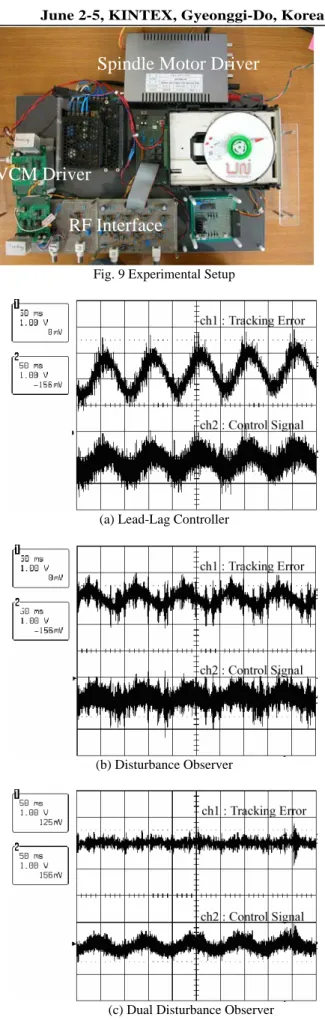
Fig. 9 illustrates the experimental setup. TMS320VC33 DSP and 16-bit ADC, DAC with 100 KHz sampling rate are used. Fig. 10 shows the experimental results, Fig. 10(a) is the result of applying a lead-lag controller. Fig. 10(b) and (c) are obtained with the lead-lag controller with DOB, and the lead-lag controller with Dual-DOB, respectively. In the Fig. 10, CH1 is tracking error and CH2 is control signal. The control signal of Fig. 10(c) is smaller than the others. The reason is that Dual-DOB is less sensitive to measurement
noise because complementary sensitivity function peak of Dual-DOB is smaller than general DOB. Through this fact, we check that the smallest tracking error is occurred in Dual-DOB system and verify effective disturbance rejection performance of Dual-DOB.
Fig. 6 Sensitivity Function
Fig. 7 Complementary Sensitivity Function
0 0.1 0.2 0.3 0.4 0.5 -100 -50 0 50 100 D is tanc e [ um ] Time [s] 0 0.1 0.2 0.3 0.4 0.5 -1 -0.5 0 0.5 1 Volt a ge [ V ] Time [s]
(a) Output Disturbance (b) Lead-Lag Controller
0 0.1 0.2 0.3 0.4 0.5 -1 -0.5 0 0.5 1 Volt a ge [ V ] Time [s] 0 0.1 0.2 0.3 0.4 0.5 -1 -0.5 0 0.5 1 Volt a ge [ V ] Time [s]
(c) DOB (d) Dual-DOB
Fig. 8 Disturbance and Tracking Error
VCM Driver
Spindle Motor Driver
RF Interface
Fig. 9 Experimental Setup
(a) Lead-Lag Controller
(b) Disturbance Observer
(c) Dual Disturbance Observer Fig. 10 Experimental Result
5. CONCLUSION
In this paper, a dual disturbance observer was proposed to reduce the effect of cross-coupling in multi loop DOB system. It was possible for us to improve the sensitivity function with additional external DOB with hardly affecting complementary sensitivity function. Designs of internal DOB loop and external loop DOB were independently made so that we prevented transient response quality from degrading while improving the sensitivity function. The proposed Dual-DOB was applied to a commercial optical disk drive tracking servo system. The experimental result showed that the Dual-DOB is an effective method in rejecting the disturbance as well as improving the tracking performance.
REFERENCES
[1] K. Ohnishi, “A new servo method in mechatronics.”
Trans. Jpn. Soc. Elect. Eng., vol. 107-D, pp. 83-86,
1987.
[2] K. Ohishi, M. Nakao, K. Ohnishi and K. Miyachi, “Microprocessor controlled DC motor for load-insensitive position servo system,” IEEE Trans.
Industrial Electronics’, vol. 34, pp. 44-49, Feb. 1987.
[3] K. Ohishi, K. Ohnishi and K. Miyachi, “Adaptive DC Servo Drive Control Tracking Force Disturbance Suppression into Account,” IEEE Trans. on Ind.
Applications, vol. 24, No.1, pp. 171-176, Jan./Feb. 1988.
[4] S. M. Shahruz, “Performance enhancement of a class of nonlinear systems by disturbance observers,”
IEEE/ASME Trans. on Mechatronics, vol. 5, pp. 319-323,
Sep. 2000.
[5] S. M. Shahruz, C. Cloet and M. Tomizuka, “Suppression of effects of nonlinearities in a class of nonlinear systems by disturbance observers,”
Proceedings of American Control Conference, vol. 3, pp.
2340-2345, 2002.
[6] Y. J. Choi, K. J. Yang, W. K. Chung, H. R. Kim, I. H. Suh, "Design of Disturbance Observer Considering Robustness and Control Performance(1): Analysis on Second Order System," Journal of Control. Automation
and Systems Engineering, vol. 8, No. 8, pp.655-664,
Aug. 2002.
[7] S. Komada, N. Machii, T. Hori, “Control of Redundant Manipulators Considering Order of Disturbance Observer,” IEEE Trans. Ind. Electron., vol. 47, No. 2, pp. 413-419, Apr. 2000.
[8] B. K. Kim, W. K. Chung, “Advanced Design of Disturbance Observer for High Performance Motion Control Systems,” Proceedings of the American Control
Conference Anchorage, AK pp. 2112-2117 May. 8-10,
2002.
[9] B. K. Kim, W. K. Chung, “Performance Predictable Design of Robust Motion Controllers for High-Precision Servo Systems,” Proceedings of the American Control
Conference Arlington, VA pp. 2249-2254 Jun. 25-26,
2001.
[10] J. Ueda, A. Imagi and H. Tamayama, “Track Following Control of Large Capacity Flexible Disk Drive with Disturbance Observer Using Two Position Sensors,”
Proc. Int. Conf. Advanced Intelligent Mechatronics, pp.
144-149, 1999.
[11] K. Fujiyama, M. Tomizuka, R. Katayama, “Digital tracking controller design for CD player using disturbance observer,” IEEE, pp. 598-603, 1998.
[12] K. J. Yang, Y. J. Choi, W. K. Chung, I. H. Suh, S. R. Oh,
"Robust tracking control of optical disk drive systems using error based disturbance observer and its performance measure," Proceedings of American
Control Conference, vol. 2, pp. 1395-1400, 2000.
[13] S. J. Kwon, W. K. Chung, "Robust performance of the multiloop perturbation compensator," Mechatronics,
IEEE/ASME Trans. on Mechatronics, vol. 7, pp.
190-200, Jun. 2002.
[14] H. T. Choi, I. H. Suh, "Disturbance Observer based Internal Model Controller Design: Applications to tracking Control of Optical Disk Drive," T. KIEE. vol. 48A, No.2, pp. 159-166, Feb. 1999
[15] H. S. Lee and M. Tomizuka, “Robust motion controller design for high-accuracy positioning systems,” IEEE Trans. Industrial Electronics, vol. 43, no. 1, pp. 48-55 Feb. 1996.