Journal of the Optical Society of Korea Vol. 20, No. 6, December 2016, pp. 694-697
694
-Cross-Correlation Measurements of Phase Noise Induced by
Relative Intensity Noise in Photodetectors
Zhewei Cao, Chun Yang*, and Zhenghua Zhou
School of Electronic Science and Engineering, Southeast University, Nanjing 210018, Jiangsu Province, China (Received June 20, 2016 : revised November 14, 2016 : accepted November 15, 2016)
Up-converted phase noise, which is induced by the low-frequency relative intensity noise (RIN) of a laser through AM-PM conversion within a photodetector (PD), is first measured here by means of a cross-correlation method. Our proposed measurement system can isolate the RIN-induced phase noise from noise contributions of other components, such as amplifiers, modulators, and mixers. In particular, shot noise and thermal noise generated from the PD are also suppressed by this method, so that standalone characteristics of the RIN-induced phase noise can be obtained. Experimental results clearly show the quantitative relationship between the RIN-induced phase noise and the incident optical power of the PD. Our findings indicate that the least RIN-induced phase noise appeared at the saturation point of the PD, which is about -162 dBc/Hz at 10 kHz offset.
Keywords : Relative intensity noise, Phase noise, AM-PM conversion, Photodetector, Cross-correlation OCIS codes : (060.0060) Fiber optics and optical communications; (140.3613) Lasers, upconversion;
(230.5160) Photodetectors; (120.3940) Metrology; (120.5050) Phase measurement
*Corresponding author: [email protected]
Color versions of one or more of the figures in this paper are available online.
*
This is an Open Access article distributed under the terms of the Creative Commons Attribution Non-Commercial License (http://creativecommons.org/ licenses/by-nc/3.0/) which permits unrestricted non-commercial use, distribution, and reproduction in any medium, provided the original work is properly cited.
*Copyright 2016 Optical Society of Korea
I. INTRODUCTION
Microwave optical links (MOLs), which generate, transport, and process microwave signals in the optical domain, have found various applications in radar, electronic warfare, radio- over-fiber systems, and satellite communication [1, 2]. The transmission of a microwave signal over an MOL can be used to distribute a reference frequency; therefore, the spectral purity of the transmitted signal is of great importance. However, the MOL contributes residual phase noise (RPN) to the reference signal [2-5], and the phase noise of the reference signal could be worsened if the RPN is too close to the signal-phase-noise floor. In general, external modulation offers advantages over direct laser-diode modulation, mainly in terms of bandwidth and linearity range [1, 2], and the intensity modulation direct-detection (IMDD) format with an external Mach–Zehnder modulator (MZM) is arguably the most prevalent architecture presently in use, but this approach leaves the noise induced by the laser’s relative intensity noise (RIN) as an outstanding source of system
performance degradation.
As a key component in the IMDD link, the photodetector (PD) could contribute its RPN to the phase noise of the reference signal. Two of the main sources of noise in the photodetection of optical carrier are the conversion of laser RIN into electronic phase noise, and the fundamental shot noise. Shot noise is related to the randomness of the incident photon stream [8, 9], while at higher powers another power- dependent effect, AM-PM conversion, is observed to adversely affect the transition from optical to microwave within the PD [5-12]. That is, the RIN could contribute to the phase noise of the reference signal through such AM-PM conversion, because it produces a change in the RF phase, since the propagation speed of the RF signal (or the PD microwave refractive index) depends on the number of carriers in the semiconductor [5-7]. In the past few years, RIN-induced phase noise in the PD has been studied by defining an AM-PM coefficient as the induced phase variation arising from power fluctuation [3-7]. However, the existing literature has focused on techniques of measuring the AM-PM coefficient
ISSN: 1226-4776(Print) / ISSN: 2093-6885(Online) DOI: https://doi.org/10.3807/JOSK.2016.20.6.694
Cross-Correlation Measurements of Phase Noise Induced by Relative Intensity … - Zhewei Cao et al. 695
FIG. 1. Schematic diagram for measuring RIN-induced phase noise. M1, 2: mixers; PS1, 2: phase shifters; MZM1, 2: Mach– Zehnder modulators; LPF1, 2: low-pass filters; PD1, 2: photodiodes; LD: laser diode; A1, 2: amplifiers.
for predicting the RIN-induced phase noise; direct, precise measurements of RIN-induced phase noise have not been deeply studied.
In this paper, we propose a new method based on cross-correlation to measure RIN-induced phase noise in an IMDD link. We measure the RIN-induced phase noise in a high-speed PD with different levels of incident optical power, and the results are verified by theory.
II. THEORY
The baseband laser RIN can be up-converted to micro-wave phase noise via nonlinearities in the PD. For low RIN levels, the predicted RIN-induced phase noise (in decibels) is given by [5, 6]
( )
( )
2 2 10log 2 opt RIN opt P d S f RIN f dP φ ⎡ ⎛ ⎞ ⎤ ⎢ ⎥ = ⋅ ⋅⎜⎜ ⎟⎟ ⎢ ⎝ ⎠ ⎥ ⎣ ⎦ (1)where SRIN(f) is the single sideband (SSB) phase noise spectral
density (dBc/Hz) at the RF offset frequency f; RIN(f) is the spectral density of the RIN; Popt is the laser’s average
optical power; and dϕ/dPopt is the RF phase-to-optical power
slope. Thus the AM-PM coefficient (in decibels) of the PD is defined as 2 2 10log 2 opt opt P d dP φ α= ⎡⎢ ⋅⎜⎛⎜ ⎞⎟⎟ ⎤⎥ ⎢ ⎝ ⎠ ⎥ ⎣ ⎦ (2)
Our proposed system for measuring the RIN-induced phase noise, is schematically illustrated in Fig. 1. It is a cross-correlation installation that has two duplicate channels, each of which is constructed as an interferometer with a double-balanced mixer biased at quadrature [13]. The micro-wave signal provided by a reference source is split into four parts; two of them go into the RF input ports of MZM1
and MZM2, while the other two provide the additional
quadrature signals to drive the mixers. This arrangement ensures that the RIN-induced phase noises are correlated in both channels, while the intrinsic noises generated by the MZMs, PDs, amplifiers, and mixers remain uncorrelated. Finally, the power spectra at the output ports of the mixers, followed by low-pass filters (LPFs), are measured by a two-channel fast Fourier transform (FFT) correlation analyzer.
The microwave source is expressed as
( )
2 sinm m m
V= V ⎡⎣ω t +φ t ⎤⎦ (3)
where ωm and ϕm are respectively the angular frequency
and phase fluctuation of the microwave source. Then the output of the MZMi (i=1, 2) is
( )
{
, cos cos DC cos
MZM i o o o m
V =E ⎣⎡ωt+φ t ⎤⎦⋅ φ +β ⎡⎣ω t+ φMZM
( )
t ⎤⎦+nRIN( )
t}
(4)
where Eo, ωo, φo, and nRIN are respectively the optical
intensity, optical frequency, optical phase fluctuation, and relative intensity noise of the laser; φdc = πVb/Vπ is the
DC-bias angle of the MZM, Vb is the DC-bias voltage, Vπ
is the half-wave voltage, and β = πVm/Vπ is the modulation
index at the microwave carrier frequency; and φiMZM is the
RPN of MZMi. Considering only the fundamental products,
the output of PDi is
( )
( )
( )
( )
, cos i i
PD i i m m MZM RIN PD
V =A ⎡⎣ω t+φ t +φ t +φ t +φ t ⎤⎦ (5)
where Ai is a compound amplitude, ϕRIN (t)=α·nRIN(t) is the
RIN-induced phase fluctuation with respect to the LD, α is the AM-PM coefficient of the PD, and ϕiPD is the RPN of
PDi. If we assume that the two arms of the interferometer
are of equal delay, the output of Mi can be expressed as
(
)
, isin i i
IF i MZM RIN PD iAmp mixei r
V =kφ φ +φ +φ +φ +φ (6)
where kiϕ is the phase-to-voltage gain of Mi (which can be
determined experimentally), and ϕiAmp and ϕimixer are the
RPN of the amplifier and mixer in the ith channel respectively. Then the cross-spectrum S12(f ) can be obtained by [13]
12( ) IF,1( ) IF,2( ) S f =V f V∗ f
(7) where VIF, 1(f ) and VIF, 2(f ) are the Fourier transforms of
VIF, 1(t) and VIF,2(t). In general, FFT analyzers (such as the
Agilent 35670A) make use of (7) by replacing the true Fourier transforms with the FFTs of VIF,1(t) and VIF, 2(t),
simultaneously sampled and averaged over N acquisitions. Thus, when dealing with discrete samples, after some lengthy manipulations (7) becomes
Journal of the Optical Society of Korea, Vol. 20, No. 6, December 2016 696 100 1000 10000 -190 -180 -170 -160 -150 -140 -130 -120 -110 -100 -90 -80 -70 -60 -50 Cross 2/1 Channel 2 S S B p h as e n o ise( d B c/ H z) Offset frequency(Hz) Channel 1
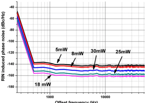
FIG. 2. Phase-noise floor of the measurement system after 6000 averaged trials. 1000 10000 -180 -160 -140 -120 -100 -80 -60 -40 R IN i n d u ced p h as e n o ise ( d B c /H z) Offset frequency (Hz) 5mW 8mW 18 mW 30mW 25mW
FIG. 3. Measured RIN induced phase noise with different incident optical power levels.
(
)
* * * *
12( ) 1 1 2 1 2
= 1
RIN RIN RIN RIN
N N N N N RIN S f T S O N ⎡ ⎤ = ⎣Φ Φ + Φ Φ + Φ Φ + Φ Φ ⎦ + (8)
where T is the truncation time of one measurement, ΦRIN
is the FFT of φRIN, Φi (i=1, 2) is the FFT of [φ iPD(t) +φ iAmp(t)
+ φ imixer (t) + φiMZM(t)], and O(·) means “order of.” Owing
to statistical independence, the cross terms decrease proportionally to . Eq. (8) indicates that the cross- correlation process can suppress the uncorrelated phase noise in each channel, while SRIN (f ), the RIN induced phase
noise, is sustained. By averaging N times, the uncorrelated phase noise can be suppressed by a factor of , in theory [13].
III. EXPERIMENT AND DISCUSSION
In the experiment, the measurement system was constructed according to Fig. 1. A microwave source at 10 GHz was used as the reference. The MOLs consisted of a 1550-nm laser, two independent MZMs, and two independent, high- optical-power-handling PDs (Discovery DSC40S). To achieve a low phase-noise floor, several low-phase-noise amplifiers (HMC606, -150 dBc/Hz at 1 kHz offset and -160 dBc/Hz at 10 kHz offset) were employed. A two-channel FFT correlation analyzer (Agilent 35670A) was used to perform power- spectrum and cross-correlation analysis. The cross-correlated noise floor for 6000 averaged trials of the measurement system is shown in Fig. 2. As we can see, the cross-correlated noise floor is significantly lower than the noise floors for the single channels: approximately 15 dB lower at 1 kHz offset, and 19 dB lower beyond 10 kHz. Therefore, the uncorrelated noise suppression beyond 10 kHz was consistent with the theoretical prediction (5logN = 19 dB, N = 6000), because the RPN spectrum was flat in this frequency range, where the independent channel noises are uncorrelated (white). The smaller noise suppression in the lower frequency range
may be explained by the correlation between the low-frequency noises of the two channels. By further increasing the average times, we observed little further reduction in the phase noise level, because the number of averaged spectra sets a statistical limit to the measurement [13].
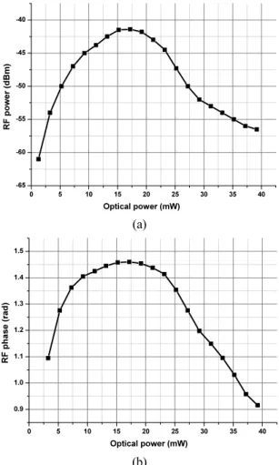
Figure 3 shows the experimental results for RIN-induced phase noise when the input optical power of the PD was changed from 5 to 30 mW. At low power levels, with increasing optical power the phase noise becomes lower. The phase noise for 18 mW of optical power is about 20 dB lower than that for 5mW, which is about -162 dBc/Hz at 10 kHz offset. However, the phase noise increases when the optical power continues to increase: The phase noise for 30mW of optical power is about 10 dB higher than for 18 mW, which is about -152 dBc/Hz at 10 kHz offset. This phenomenon can be explained by Figs. 4(a) and (b), which illustrate the power and relative phase of the RF signal at the output of the PD, as a function of the RF- modulated optical power at the input of the PD. At low input optical power, the RF power and RF relative phase both increase with input power, but as the input power approaches the PD saturation power, the slopes of the curves both decrease and reach zero at the saturation power, which is about 17-18 mW. As can be seen from eq. (1) and (2), zero slope indicates that the contribution of RIN-induced phase noise is small or zero at the PD, so the RIN-induced phase noise is related to the nonlinearity of the PD, and the best phase noise performance occurs at the saturation point. Thus the experimental results for RIN-induced phase noise using our proposed measurement system are consistent with theory.
IV. CONCLUSION
In this paper, we present a novel approach for directly measuring a laser’s RIN-induced phase noise in a PD, using a cross-correlation-based method. This method can effectively suppress the RPN of other components in the
Cross-Correlation Measurements of Phase Noise Induced by Relative Intensity … - Zhewei Cao et al. 697 0 5 10 15 20 25 30 35 40 -65 -60 -55 -50 -45 -40 RF po we r (dB m ) Optical power (mW) (a) 0 5 10 15 20 25 30 35 40 0.9 1.0 1.1 1.2 1.3 1.4 1.5 R F p h as e ( ra d ) Optical power (mW) (b)
FIG. 4. (a) Measured RF output power versus input optical power of the PD. (b) Measured input-to-output relative phase versus input optical power of the PD.
MOL, which is the uncorrelated phase noise during measurement. By averaging 6000 trials, the uncorrelated phase noise beyond the 10-kHz frequency offset was suppressed by 19 dB, which is consistent with the theoretical prediction. Then the RIN-induced phase noise for different levels of incident optical power was measured, the results showing that minimum AM-PM conversion rate appears at the saturation point of the PD, and that the best RIN-induced phase-noise performance in the measurement is about -162 dBc/Hz at 10 kHz offset. The oversaturated state of the PD may worsen the phase noise, because AM-PM conversion will continue, in part due to saturation and other nonlinearities in the strongly driven PD. This suggests that the proposed method can give a quantitative measure of this kind of up- converted phase noise, and is helpful for designing high- performance microwave photonic systems.
ACKNOWLEDGMENT
This study was supported by the National Natural Science Foundation of China (Grant No. 61671148).
REFERENCES
1. C. H. Cox, Analog Optical Links: Theory and Practice (Cambridge University Press, Cambridge, UK, 2006). 2. M. B. Bibey, F. Deborgies, M. Krakowski, and D. Mongardien,
“Very low phase-noise optical links-experiments and theory,” IEEE Trans. Microw. Theory Techn. 47, 2257-2262 (1999). 3. M. Currie, I. Vurgaftman, “Microwave phase retardation in
saturated InGaAs photodetectors,” IEEE Photon. Technol.
Lett. 18, 1433-1435 (2006).
4. W. Zhang, T. Li, M. Lours, S. Seidelin, G. Santarelli, and Y. Le Coq, “Amplitude to phase conversion of InGaAs pin photo-diodes for femtosecond lasers microwave signal generation,” Appl. Phys. B 106, 301-308 (2012).
5. D. Eliyahu, D.Seidel, and L. Maleki, “RF amplitude and phase-noise reduction of an optical link and an opto-electronic oscillator,” IEEE Trans. Microw. Theory Techn. 56, 449-456 (2008).
6. J. Taylor, S. Datta, A. Hati, C. Nelson, F. Quinlan, A. Joshi, and S. Diddams, “Characterization of power-to-phase conversion in high-speed P-I-N Photodiodes,” IEEE Photon.
J. 3, 140-151 (2011).
7. X. Zhang, T. D. Ni, A. S. Daryoush, “Laser induced phase noise in optically injection locked oscillator,” in Proc. IEEE MTT-S International Microwave Symposium Digest (Albuquerque, NM, USA, Jun. 1992), pp. 765-768.
8. R. R. Hayes and D. L. Persechini, “Nonlinearity of p-i-n photodetectors,” IEEE Photon. Technol. Lett. 5, 70-72 (1993). 9. K. J. Williams, R. D. Esman, and M. Dagenais, “Nonlinearities
in p-i-n microwave photodetectors,” J. Lightwave Technol. 14, 84-96 (1996).
10. E. Rubiola, E. Salik, N. Yu, and L. Maleki, “Flicker noise in high-speed p-i-n photodiodes,” IEEE Trans. Microw.
Theory Techn. 54, 816-820 (2006).
11. D. A. Tulchinsky and K. J. Williams, “Excess amplitude and excess phase noise of RF photodiodes operated in
compression,” IEEE Photon. Technol. Lett. 17, 654-656 (2005).
12. D. A. Tulchinsky and K. J. Williams, “Phase noise in compressed RF photodiodes,” in Proc. IEEE International Topical Meeting on Microwave Photonics (Oct. 2004), pp. 269-272.
13. E. Rubiola and F. Vernotte, “The cross-spectrum experimental method,” arXiv:1003.0113 [physics.ins-det], Feb. 27 (2010).