CHF Characteristics of R-134a Flowing Upward in an Annulus Geometry
Kwi Lim Lee and Soon Heung ChangDept. of Nuclear & Quantum Engineering, KAIST, Daejeon, Republic of Korea Tel: +82-42-869-3856, Fax: +82-42-869-3810, E-mail: [email protected]
1. Introduction
The critical heat flux in case of forced convective boiling is a phenomenon that has been thought as one of the most important parameter in designing and operating the heat transfer equipments. The regime has been adopted in a lot of applications including nuclear power plants, fossil power plants, steam generators, refrigeration systems and spray cooling, In particular, this regime has a considerable importance in the areas of light water reactor (LWR) accident analysis and design in heat exchangers operating in the once-through mode where subcooled liquid enters the exchanger and superheated vapor exits. Although many aspects of CHF have been studied to understand the phenomena and predict the CHF condition for the expected equipments, experimental investigations are usually limited to the simplified geometry due to the high complexity of the test facility. [1]
Recently, innovative PWRs adopt very high power density increases and so require increased safety margins. Therefore, it requires improved knowledge of heat transfer in the region which is extremely important to safety analysis and assessments. Even though actual PWR fuel geometry is a type of bundle with rods, an annular geometry with only single rod called as one-rod bundle is more attractive than circular tube geometry with inside flow in simulating and understanding various CHF phenomena even including enhancement techniques like grid and vane. In addition, it has another merit to adopt visualization strategy for understanding heat transfer mechanisms.[2] Ozone-safe Refrigerant 134a is being widely used due to its low latent heat and low boiling temperature as a simulation fluid of high pressure- high temperature water condition because actual water test in the extreme conditions is significantly difficult [3]. Therefore, the main objective of this study is to provide an R-134a CHF database and to investigate the CHF characteristics of the R134a flowing upward in an annulus channel.
2. Experimental Method
An experimental study will be carried out in R-134a thermal-hydraulic loop of KAIST to investigate the effects of a spacer grid in an annulus flow channel with a rod. The experimental loop consists of a closed R-134a flow loop with test section, pump, mass flow meter, pressurizer (accumulator and N2 gas bottle), pre-heater,
chiller (cooling of R134a fluid using refrigerant gas), auxiliary device (vacuum pump removing moisture for purity and chiller pump) and other instrumentation.
P DP P T T T T T P r e h e a te r A c c u m u la to r N 2 G a s T e st S e c ti o n
Condenser Heat ExchangerChiller
T
P T
P
Vacuum Pump Mass Flow Meter
R22 Compressor Strainer Bypass Bypass Throttling Water Pump P P Condenser Water Tank Water Coolant Fan Pump
Figure 1. Schematic diagram of the experimental test loop [3]
Figure 2. Schematic diagram of the test section
The test section consists of a body of a inner rectangular flow channel of 19x19 mm2 and single heater rod with outer diameter of 9.5 mm, and six K-type thermocouples, whose sheath diameter is 0.5 mm, are
Transactions of the Korean Nuclear Society Autumn Meeting Busan, Korea, October 27-28, 2005
embedded in the cladding of the heater rod to measure the wall temperature. The length from the bottom end of heated section to each thermocouple is 920, 1320, 1520, 1720, 1800, 1820 mm, respectively [4]. For the measurement of fluid temperature, four K-type thermocouples are installed in the annulus flow channel and four pressure taps are drilled at the flange. The rod over a length of 1830 mm is indirectly heated by a heat element heated directly. Power shape of the heater rod is uniform throughout the heated section. The schematic diagrams of test loop and the test section are shown in Figs. 1 and 2, respectively. In particular, for observation of characteristic heat transfer phenomena, visual windows are installed in the exit part including the last spacer.
3. Experiment
In the present study experiments were conducted for the refrigerant mass flux varying from 100 to 600 kg/m2s, the pressure of 11.6, 16, and 20 bar and the subcooling temperature from 23 to 40oC. The following table shows the test condition.
Table1. Test condition
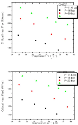
The results of the present works represent the characteristics of the flow boiling heat transfer for R-134a in an annular channel by presenting the critical heat flux. In particular, Fig. 3 shows the effect of the inlet subcooling on the R-134a flow CHF while Fig. 4 shows the trend of CHF data for different mass flux and pressures. The data for a fixed pressure reveals that the critical heat flux decreases almost linear as the subcooling temperature increases. These trends agree with the general understanding in the water.
4. Conclusion
An experimental study of the critical heat flux (CHF) using R-134a in uniformly heated vertical tube was performed in case of annular channel. Experimental data on the temperature of R-134a flow in an annulus channel have been obtained. The parametric trends of the CHF show a general agreement with previous studies. In future, we will add the works related to not only CHF including a comparison with water data using a fluid-to-fluid model but also Post-CHF.
24 26 28 30 32 34 36 38 40 42 140 160 180 200 220 240 C ri ti c a l H e a t F lu x (k W /m 2 ) T e m p e r a t u r e o f T i n( oC ) G = 6 0 0 P - 1 1 . 6 b a r P - 1 6 b a r P - 2 0 b a r 24 26 28 30 32 34 36 38 40 110 120 130 140 150 160 C ri ti c a l H e a t F lu x( k W /m 2) T e m p e r a t u r e o f T i n( oC ) G = 3 0 0 P - 1 1 . 6 b a r P - 1 6 b a r P - 2 0 b a r
Figure 3. Effect of inlet subcooling on CHF of R-134a in vertical tube ( mass flux : 600 and 300 kg/m2s )
24 26 28 30 32 34 36 38 40 115 120 125 130 135 140 145 150 155 160 165 170 175 180 185 190 195 200 205 210 215 C ri ti c a l H e a t F lu x (k W /m 2 ) T e m p e r a t u r e o f T i n ( oC ) P = 1 6 b a r G - 3 0 0 G - 4 5 0 G - 6 0 0 20 25 30 35 50 60 70 80 90 100 110 120 130 140 150 160 170 C ri ti c a l H e a t F lu x (k W /m 2 ) T e m p e r a t u r e o f T i n (oC ) 1 1 . 6 b a r 1 0 0 3 0 0 6 0 0
Figure 4. Effect of inlet subcooling on CHF of R-134a in vertical tube ( outlet pressure : 16 bar and 11.6 bar )
REFERENCES
[1] Chang Ho Kim, Soon Heung Chang, CHF characteristics of R-134a flowing upward in uniformly heated vertical tube, Heat and Mass Transfer, 48, 2242-2249,2005
[2] Soon Heung Chang, Won-Pil Baek, Critical heat flux –fundamentals and applications, Chungmoongak Pub. Co., Seoul, 1997 (in Korean)
[3] In Cheol Bang, Soon Heung Chang and Won-Pil Baek, Visualization of the subcooled flow boiling of R-134a in a vertical rectangular channel with an electrically heated wall, International Journal of Heat and Mass Transfer, Volume 47, Issues 19-20, September 2004, Pages 4349-4363.
[4] S. Cho, S.-Y. Chun, M.-K.Chung, and W.-P. Baek, Spacer grid effects in an annulus geometry during reflood, NTHAS4, 2004
Experimental parameter Experimented condition
Pressure [bar] 11.6, 16, 20 Mass flux [kg/m2s] 100 ~ 600 Tin [oC] 23 ~ 40 A Location of K-type thermocouples [mm] 920,1320,1520,1720, 1800,1820 Heated length [mm] 1830
![Figure 1. Schematic diagram of the experimental test loop [3]](https://thumb-ap.123doks.com/thumbv2/123dokinfo/4970025.52803/1.892.463.783.351.582/figure-schematic-diagram-experimental-test-loop.webp)