Figure 1 schematic diagram of experimental facility
The thermal-hydraulic performance of PCHE in an air test loop
Sung Chu Song1, Hee Cheon NO1, Cheol Shin Lee21
Korea Advanced Institute of Science and Technology, 373-1, Guseong-dong, Yuseong-gu, Daejeon, 305-701, Korea [email protected], [email protected]
2
Korea Power Engineering Co., Inc., 150 Dukjin-dong, Yuseong-gu, Daejeon, 305-353, Korea-
1. Introduction
A High Temperature Gas cooled Reactors (HTGR) with a closed cycle gas turbine has become more interested for the future. It, theoretically able to provide efficiency higher than classical steam cycle, needs very high-performance components, such as the helium/helium recuperator. Within a indirect Brayton cycle, the heat exchanger is under very harsh conditions: temperature, pressure, pressure difference between the primary and secondary sides. Thus, no directly available compact technologies exist since they are often used for cryogenic, air cooling and automotive systems which are far from the HTGR or PBMR requirements. The key component is an intermediate heat exchanger (IHX) at the indirect cycle of HTGR. Here, a Printed Circuit Heat Exchanger (PCHE) is studied to see its thermal-hydraulic characteristics.
2. Test facility and Experiments
2.1. Experimental facility
The schematic diagram of the PCHE experimental facility is shown in Figure 1. The PCHE, which is made of Alloy 800H, was provided by Heatric Co. (UK). It is composed of the independent open loop in which working fluid is air. The core dimension of KAIST PCHE has a design heat load of 55 kW and its dimension is 150 x 896 x 144 (mm x mm x mm). Also it has a dry mass of 146 kg. The total number of flow
channels is 1280 (20 x 64) for each side. The flow channels, which are composed of a countercurrent flow, are described as a zigzag line of semicircle profile with 1.51mm diameter and the hydraulic diameter of the passage is 0.922 mm. The free flow area in both hot and cold sides is 0.001155m2.
The air passing through air filter and lubricator is heated by separate heaters (20kW in hot side, 10kW in cold side). The pressure drop in the heat exchanger was measured using a differential gauge with an accuracy of ±0.2% over the full range of 100kPa. The accuracy of the flow meter was ±2% of full scale, 300-2800 LPM. The temperatures were measured using 8 K-type thermocouples with an accuracy of ±1.5℃ at each side. Also, the pressure was measured using 6 pressure gauges with an accuracy of 0.5%.
2.2. Experiments
The PCHE experiment using air was conducted in range of laminar region (Re < 2100). The maximum flow rate is 125 kg/hr. The maximum temperatures of the heat outlet are up to maximum 400℃ in the hot side and 200℃ in the cold side.
The effectiveness, η, is defined as the ratio of the actual heat transfer rate to the maximum possible heat transfer rate. The pressure drop between the PCHE inlet and outlet was measured.
The average Reynolds number was about 1100 in the hot and cold sides, respectively.
Transactions of the Korean Nuclear Society Autumn Meeting Busan, Korea, October 27-28, 2005
. The inlet temperatures of hot and cold sides are 360℃ and 200℃, respectively. The average pressures of the inlets of hot and cold sides were 2 bars for flow rate 111kg/hr.
3. Results and Discussion
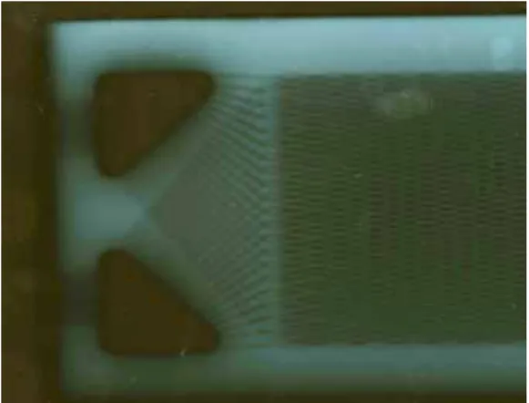
At first, the internal structure of PCHE through the fluoroscope is shown in Figure 2, which is the top view of PCHE. It was taken by X-ray photographer (LINAC ML-8R made by Mitsubish electric co.). The black triangle part represents empty space in which the heated air is distributed. The Plate has 1.5mm of thickness.
The present experimental data for the PCHE performance are not enough. The differential pressure was about 69/71 kPa (hot/cold side) at 360/200 ℃, respectively. In some tests, the outlet temperature of the hot side was lower than the inlet temperature of the cold side.
4. Conclusions
The test facility for the PCHE experiment using air was set up to see its thermal-hydraulic characteristics. Geometrical information of PCHE was investigated by fluoroscope. Through the experiment we obtained the thermal-hydraulic data which will be used in computational modeling.
REFERENCES
[1] John E. Hesselgreaves, Compact Heat Exchangers, Pergamon, 2001
[2] Patrice Tochon et al, The use of Compact Heat Exchangers technologies for the HTRs recuperator application per proper design, 2nd international topical meeting on HTR technology, #E09, 2004