Experimental Assessment of Ex-Reactor Vessel Cooling Capability of
KSNP Insulation Geometry
Sang Won Lee, Kwang Ok Jeon, Seok Ho Lee, Heung Tak Kim, Seung Jong Oh
Korea Hydro & Nuclear Power Co., Ltd., Munji-Dong Yusung-Gu, Daejeon, 103-16, Korea Tel:+82-42-865-7669 , Fax:+82-42-865-7609 , Email:[email protected]
1. Introduction
The Ex-Reactor Vessel Cooling (ERVC) strategy is implemented in the Severe Accident Management Guideline (SAMG) of KSNP. The main purpose of this procedure is to prevent the Molten Core Concrete Interaction (MCCI). However, this action might mitigate the accident scenario. One of the expected sequences is that the water contacts with the reactor vessel lower plenum could remove the heat generated by the decay and chemical reaction. This heat removal effect can mitigate the reactor vessel rupture or delay the event propagation. So, in this paper, the cooling capability of ERVC in KSNP specific insulation geometry is investigated experimentally.
2. Cavity Flooding Strategy in KSNP SAMG When the postulated severe accident that leads to the core damage occurs, injection of the cooling water to the containment could be the effective means to mitigate the accident scenario. In KSNP SAMG strategy1), the containment and reactor cavity sump is filled with cooling water by this procedure and it lead to the following effect. z MCCI can be minimized by preventing the contact with the concrete when the corium is relocated in the reactor cavity
z Reactor vessel rupture can be prevented or delayed, at least, by ERVC when the water level is above the RV lower head.
z Release of gaseous, aerosol radioactive material to the containment can be minimized due to the de-solution by the cooling water
3. Experimental Approach
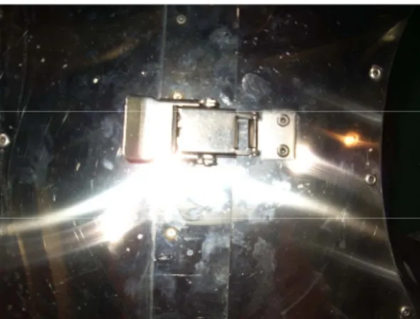
KSNP reactor vessel is insulated with the stainless-steel type insulator. The purpose of this insulation is to prevent the heat loss to the containment and also prevent the concrete degradation during the normal operation. This insulation is made of a lot of pieces and connected with the buckle type fastener. When the cooling water is injected into the reactor cavity, some of the water penetrates via the gap between the connections due to the hydrostatic head difference. In this configuration, the evaporating water near the reactor vessel wall should be filled by the penetrating water to provide continuous cooling performance.
Fig. 1 Buckle Fastener Type Insulator configuration
3.1 representative discharge coefficients
The penetrating water flow-rate is highly depends on the insulation configuration including the connection length, distribution, and gap between the connection. The connection length and distribution can be obtained by the detailed installation diagram. But the gap size cannot be obtained or measured. To model the flow characteristic due to gap size, three kinds of approach is examined based on the preliminary experimental results as shown in Fig 2.
Fig. 2 Water level vs. time
i. Discharge coefficient, Cd
Based on the conventional definition of the discharge coefficient , Cd is defined as;
Transactions of the Korean Nuclear Society Autumn Meeting Busan, Korea, October 27-28, 2005
gh dt dh d C 2 1 × = Eq. 1
ii. Modified discharge coefficient, Cl
Above Cd definition does not consider the gap size. Even though Cd is applicable to these flow characteristics, additional gap size information should be assumed. To eliminate the effect of gap size, the modified discharge coefficient, Cl, is considered as ; gh L W gap C l C f w d 2 ρ × = × ≡ Eq. 2
iii. Overall discharge coefficient, Coverall
To simplify the effect of the gap size and the water level dependency, the overall discharge coefficient is defined as ; L Ww gh C overall C ≡ l×ρf 2 = Eq. 3
Evaluation about the above three coefficient results is summarized in Table 1.
Table 1 representative coefficient calc. results
Mean STD STD / Mean
Cd 2.36E-4 2.33E-5 9.9% Cl 4.1E-5 2.7E-6 6.4%
Coverall 0.1 0.032 32%
As shown above table, the modified discharge coefficient is the less dependent on the water level. So, in this experiment, the modified Cl is used as a representative parameter.
3.2 Experimental results
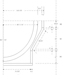
To assess the penetration characteristic and the cooling capability, the overall connection length(L) is calculated based on the Ulgin 5,6 insulation installation P&ID. And is converted into the 1/2 slice type insulation and reactor vessel experimental facility as shown in Fig 3.
The test procedure is that the water is injected through four flow path based on the pre-calculated flow-rate. And the cooling capability is examined until quasy-steady state is reached. The results show that the heat removal capability is maintained and the evaporating flow-rate is sufficiently provided by the penetration flow-rate until 50kW power level. However, the water level is not maintained above the 50kW and critical heat flux is observed before quasy-steady state reach.
Fig. 3 Schematics of Exp. Facility Lower Head
Fig. 4 Penetrating water flow-rate vs. power supply 4. Conclusions
The ERVC cooling capability against KSNP specific insulation design is experimentally investigated. The result shows that the cooling capability is maintained until 50kW power level (~15MW for plant scale). So, when the accident scenario that are not exceed the above power level, the ERVC strategy is a effective means to prevent the reactor vessel rupture. The detailed accident scenario and uncertainty quantification is needed to assess the overall effect of this strategy.
REFERENCES
[1] KHNP, Severe Accident Management Guideline, 2002 [2] EPRI, SAMG TBR Vol. 2, 1994