저작자표시-비영리-변경금지 2.0 대한민국 이용자는 아래의 조건을 따르는 경우에 한하여 자유롭게 l 이 저작물을 복제, 배포, 전송, 전시, 공연 및 방송할 수 있습니다. 다음과 같은 조건을 따라야 합니다: l 귀하는, 이 저작물의 재이용이나 배포의 경우, 이 저작물에 적용된 이용허락조건 을 명확하게 나타내어야 합니다. l 저작권자로부터 별도의 허가를 받으면 이러한 조건들은 적용되지 않습니다. 저작권법에 따른 이용자의 권리는 위의 내용에 의하여 영향을 받지 않습니다. 이것은 이용허락규약(Legal Code)을 이해하기 쉽게 요약한 것입니다. Disclaimer 저작자표시. 귀하는 원저작자를 표시하여야 합니다. 비영리. 귀하는 이 저작물을 영리 목적으로 이용할 수 없습니다. 변경금지. 귀하는 이 저작물을 개작, 변형 또는 가공할 수 없습니다.
A MASTER’S THESIS
STUDY ON THE MONO-PILE FOUNDATION OF
OFFSHORE WIND TURBINE BY USING P-Y
CURVE
JEJU NATIONAL UNIVERSITY
GRADUATE SCHOOL
Department of Civil & Ocean Engineering
Myeongjin Go
STUDY ON THE MONO-PILE FOUNDATION OF
OFFSHORE WIND TURBINE BY USING P-Y
CURVE
Myeongjin Go
(Supervised by Professor Namhyeong Kim)
A thesis submitted in partial fulfillment of the requirement for the degree
of Master of Engineering
2014. 2
This thesis has been examined and approved
Thesis director, Youngteck Hur, Senior Researcher of K-water
Thesis director, Minsu Park, Chief Researcher of KICT
Thesis director, Namhyeong Kim, Prof. of Civil Engineering
February. 2014
Department of Civil & Ocean Engineering
CONTENTS
List of Figure ⅲ List of Tables ⅳ Summary ⅴ CHAPTER1 : Introduction 1 1.1 Background 1 1.2 Objectives 3 1.3 Study Contents 3CHAPTER2 : Basic Equation for External Force 5
2.1 Wind Force acting on the Tower 5
2.2 Wave Force acting on the Tower 6
2.3 Calculation of p-y Relation 7
2.4 Blade Element Momentum Theory 8
2.5 Thrust Force 9
CHAPTER3 : Verification and Consideration 10
3.1 Verification of cohesive soil 10
3.2 Verification of Sandy Soil 11
CHAPTER4 : Application 13
4.1 Calculation of External Force 13
4.2 Calculation of Foundation 16
4.2.1 Calculation of Foundation in Cohesive Soil 16
4.2.2 Calculation of Foundation in Sandy Soil 20
CHAPTER5 : Conclusions and Remarks 26
5.1 Conclusions and Remarks 26
5.2 Future works 27
List of Figures
Fig. 1 Simple model of offshore wind turbine and forces in Andersen et al.(2012) 12 Fig. 2 Displacement and soil reaction by external forces 13 Fig. 3 Simple model of offshore wind turbine and forces in Jang et al.(2013) 14
Fig. 4 Displacement and moment by external forces 15
Fig. 5 The simple model of calculation condition 17
Fig. 6 Thrust force of the designed blade 18
Fig. 7 Wind forces acting on the offshore wind tower according to wind
velocities 19
Fig. 8 Wave forces acting on the offshore wind tower according to wind
velocities 19
Fig. 9 Displacement in cohesive soil 20
Fig. 10 Subsoil reaction in cohesive soil 21
Fig. 11 Shear force in cohesive soil 21
Fig. 12 Moment in cohesive soil 22
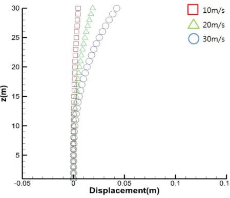
Fig. 13 Displacement in sandy soil 23
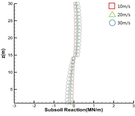
Fig. 14 Subsoil reaction in sandy soil 24
Fig. 15 Shear force in sandy soil 24
Fig. 16 Moment in sandy soil 25
Fig. 17 Displacement in multi-layered soil 26
Fig. 18 Subsoil reaction in multi-layered soil 27
Fig. 19 Shear force in multi-layered soil 27
List of Tables
Table 1. Determination in the index in any regions(Coastal Development Institute of
Technology, 2011) 6
Table 2. Structural properties of wind turbine model in Andersen et al. (2012) 12 Table 3. Structural properties of wind turbine model in Jang et al. (2013) 14 Table 4. Structural properties of wind turbine model 17 Table 5. Maximum values of response in cohesive soil 22
Table 6. Maximum values of response in sandy soil 25
Summary
By the environmental pollution, global warming and resource depletion owing to the utilization of fossil fuel, various green energies has been recently in the spotlight. Of these, interest in the wind energy has been increased since the high quality wind resources are obtained both in onshore and offshore.
Wind, the driving force for the wind power generation as one of the green energies, is observed higher quality value in the offshore than that of onshore. Also, the development of offshore wind towers has been in the spotlight as an alternative method in order to solve the problems of onshore wind farm such as securing sites, noise, and electromagnetic waves, and in order to get efficient wind power energy. Therefore, the many researches on offshore wind energy have been carried out.
As wind towers are advanced to ocean, offshore wind towers have been enlarged. Also, various external forces such as wave force and collision of vessel and tidal current, act on offshore wind tower. Thus, the stability of offshore wind tower is required to endure wind force and wave force.
Mono-piles are often applied as foundations for offshore wind tower at water depths less than 30m. In this type of foundation, subsoil conditions affect to endure external force. The various soil conditions make different soil reaction and displacement.
In this study, the external forces act on the foundation. And the calculation is carried out, for the various soil conditions such as cohesive soil, sandy soil and multi-layered. The wave force is calculated by Morrison’s equation, and thrust force is analyzed by BEMT(Blade Elemental Momentum Theory). Using computed external
forces, displacement of offshore wind tower and subsoil reaction are calculated.
As a result, the understanding of the stability in offshore wind tower with various soil conditions is improved, and the various soil conditions are considered for the safety evaluation.
CHAPTER 1
INTRODUCTION
1.1 Background
Recently, various problems such as global warming, rising of sea water level, and exhaustion of resource occurred by the utilization of fossil fuel. Therefore, the development of green energies such as wind, tide, wave, and solar has been in the spotlight. Of these, interest in the wind energy is increased since the wind resources are obtained both in onshore and offshore(Nah et al. 2011).
Wind, the driving force for the wind power generation, is observed higher quality value in offshore than that of in onshore. Therefore, the development of offshore wind turbines is expected to get efficient wind power energy, because the electricity of wind power is increased with the increase of wind velocity(Kim and Jin, 2012).
Though the development of offshore wind turbine has shown efficient wind power energy, leading to problems by larger size than that of onshore wind tower. As offshore wind towers have been enlarged, larger wind forces act on the offshore wind tower. Also, various external forces, such as wave force and collision of vessel and tidal current act on offshore wind tower. For these reasons, many researches have been carried out on offshore wind tower.
Gaudiosi (1999) presented the research of offshore wind energy prospects about the european countries. In Japan, study on the predominance of offshore wind turbine was carried out by Iguchi et al. (2000), and study on the development of medium
and large scale wind turbine in coastal zone was carried out by Nagai et al. (2008). In Korea, Kyoung et al. (2003) assessed wind power resources around Korean Peninsula, and Kim and Jin(2010) assessed wind energy potential around Jeju coastal area. Kim et al. (2007), Kim and Cao(2008) performed numerical analysis on the wave force acting on the vertical cylinders.
Several methods have been proposed for the analysis of lateral pile response, including first and foremost the p–y method suggested about 55 years ago. In this method, the lateral capacity in terms of displacement, bending moment, and shear force are determined by modelling the pile as a beam and the soil as a system of uncoupled lateral springs known as a Winkler model. The springs are described by p –y curves defining the load–displacement relationship for the interaction between soil and pile. Today, the p–y method is the standard procedure for the design of laterally loaded piles recommended in the relevant guidelines for offshore engineering(Andersen et al., 2012).
Andersen et al. (2012) analyzed natural frequencies of wind turbines on mono-pile foundations in clayey. Three-dimensional numerical analysis of mono-pile foundation was calculated by Lee et al. (2011). Jang et al. (2012) executed lateral behavior of offshore wind turbine mono-pile foundation embedded in sandy soil.
However, results from domestic studies on the offshore wind tower are not sufficient than those obtained from abroad because data from abroad studies are applied to the domestic situations. Also, the analysis of multi layered soils are rarely carried out owing to the less number of analysis and experiments. Therefore, studies on the offshore wind tower have been actively progressing in order to understand the effect of external forces and behavior of subsoil.
1.2 Objectives
Offshore wind tower is exposed to various external forces according to wind velocity. Therefore, the stability of offshore wind tower foundation and analysis in various soil conditions are required.
For verification of analysis using p-y relation in cohesive soil and sandy soil, the results obtained from this study are compared with the results of Andersen et al. (2012) and Jang et al. (2013).
Today, foundation-soil system is analyzed by p-y relation. However, it is limited in single-layered soil due to the difficulties of verification. Understanding of effect of soil condition can be improved through the comparison among cohesive soil, sandy soil, and multi-layered soil. Therefore, it is considered at base data on stability analysis of offshore wind tower.
1.3 Study Contents
This study calculates various external forces such as wind velocity, thrust force, wind force, and wave force. Then, the displacement and subsoil reaction are analyzed using various soil conditions with p-y relation.
To verify, results obtained from this study are compared with the results of Andersen et al. (2012) and Jand et al. (2013).
force, wave force, displacement, soil reaction, shear force and moment are calculated for various soil conditions with p-y relation.
CHAPTER 2
Basic Equation for External Force
2.1 Wind Force acting on the Tower
Offshore Wind Power Generation Technical Manual (Coastal Development Institute of Technology, 2011) is referenced to calculate the wind force acting on the offshore wind tower as follow:
∙∙ (1) ∙
∙
∙∙ ≤ ∙ ≥ where is the wind force acting on the offshore wind tower, is the windward wall of the offshore wind tower (m2),
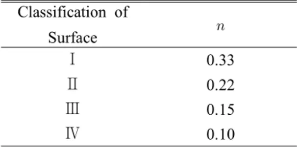
is the height above mean sea surface (m), is the diameter (m), is the wind speed (m/s), and is the index from Table 1.
In this study, is 0.10 because a few obstacles are observed in coastal area. is
a gust coefficient, which is referenced from Offshore Wind Power Generation Technical Manual. is 250.
Table 1. Determination in the index in any regions(Coastal Development institute of Technology, 2011) Classification of Surface Ⅰ 0.33 Ⅱ 0.22 Ⅲ 0.15 Ⅳ 0.10
2.2 Wave Force acting on the Tower
In the ocean, there are variety types of forces such as a wave force, a collision of vessel and a tidal current. Of these, the wave force is a very important phenomenon for the threat to stability of wind tower due to constant action. In the offshore, wave is changed according to the wind velocity. The significant wave height and period of developed wave in wind field are calculated by SMB method, Eqs. (2) and (3)(Nakamura et al., 2002). (2)
(3)where is wind velocity (m/s), is gravitational acceleration (m/s2). Maximum
(4)
Through above calculated wave condition, wave force acting on offshore wind tower is computed. IEC 61400-1 suggests the Morrison’s equation to calculate the wave force acting on the offshore structure as follow:
(5)where is the horizontal wave force of , is the sea water density, and
is a drag coefficient. is a mass coefficient, is the tower diameter (m), is
the horizontal water particles speed (m/s), and is the horizontal water particles acceleration (m/s2).
2.3 Calculation of p-y Relation
Several methods have been proposed for the analysis of lateral pile response, including first and foremost the p–y method suggested about 55 years ago. In this method, the lateral capacity in terms of displacement, bending moment and shear force are determined by modelling the pile as a beam and the soil as a system of uncoupled lateral springs known as a Winkler model. The springs are described by p –y curves defining the load–displacement relationship for the interaction between soil and pile. Today, the p–y method is the standard procedure for the design of laterally loaded piles as recommended in the relevant guidelines for offshore engineering (Andersen et al., 2012). If the ground is assumed to be elastic condition, soil reaction can be calculated by Eq. (6).
(6)
where is the soil modulus, is the horizontal displacement of foundation (m),
is the diameter of foundation (m), and is depth of foundation (m).
2.4 Blade Element Momentum Theory
The design of wind turbine rotor blade, the reliable decision of the rated wind speed and the design wind speed are started through measuring wind data for several years in installed sites. It is necessary to observe for the wind resource in order to making accurate decisions of the design wind speed and the reliable design of the wind turbine. The rotor diameter of the wind turbine is determined by Eq. (7) (Kim et al., 2008).
(7)where is rotor diameter (m), is the rate power, is efficiency of the
generator, is the rotor power coefficient, is the density of air, and is the
design wind speed (m/s).
Eq. (8) suggested by Ludwig Prandtl in 1919(Kim and Jin, 2013).
(8)
where is the local position from the hub, is the tip loss factor, is the number
of the blades and is the axial induction factor.
The local chord length of the blade is induced to the Eq. (9) form BEMT (Blade Element Momentum Theory) which is general modeling method of the wind turbine.
(9)
where is a optimum lift coefficient, is the local radius, and is tip to speed
ratio, 6.
2.5 Thrust Force
The rotor of offshore wind turbine in rated wind speed revolves. Displacement of offshore wind tower is affected by change of thrust force because its force is generated in the opposite direction with wind force. Therefore, in a range of the rotor operation, thrust force is important factor in analysis of offshore wind tower. Thrust force is written as follows:
(10)
CHAPTER 3
Verification
In this study, verification models of two types are fulfilled. To verify the results from the developed program, the analysis are compared to the results computed from cohesive soil by Andersen et al. (2012) and sandy soil by Jang et al. (2013).
3.1 Verification of cohesive soil
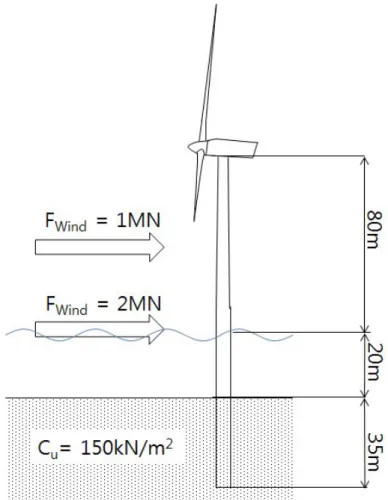
The behavior of the offshore wind tower foundation embedded in cohesive soil was analyzed by Anderen et al.(2012). For analysis of this study, soil conditions are considered as all cohesive soil. The embedded depth and undrained shear strength are 35m and 150 respectively. The height of tower is 100m. The wave force and the wind force are 2MN and 1MN, respectively(Fig. 1 and Table 2).
In order to obtain the displacement and the soil reaction of the structure-foundation-soil system, an equivalent coupled-spring model has been calibrated to the pile head response.
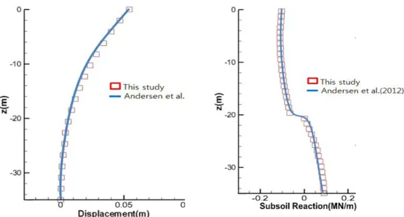
For verification, calculation is carried out with same condition presented from Andersen et al. (2012). The Fig. 2 shows the comparison of this study with result of Andersen et al. (2012). The comparison shows good agreement between this study and results of Andersen et al. (2012).
occurred in pile head. Also, subsoil reactions are reduced from bottom to half of foundation and are increased from half to top.
Fig. 1 Simple model of offshore wind turbine and forces in Andersen et al. (2012) Table 2. Structural properties of wind turbine model in Andersen et al. (2012)
Model Property Calibrated Values
Elastic modulus of tower structure (N/m2) 2.05 * 1011
External diameter of tower structure (m) 6.40
Wall thickness of tower structure (m) 0.035
Height of tower structure above the seabed (m) 1.00 * 102
Mass density of tower (kg/m3) 8.45 * 103
Fig. 2 Displacement and soil reaction by external forces
3.2 Verification of Sandy Soil
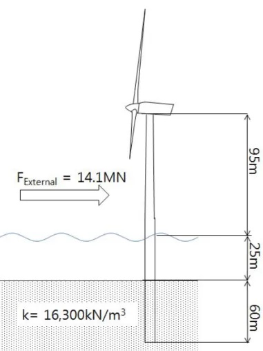
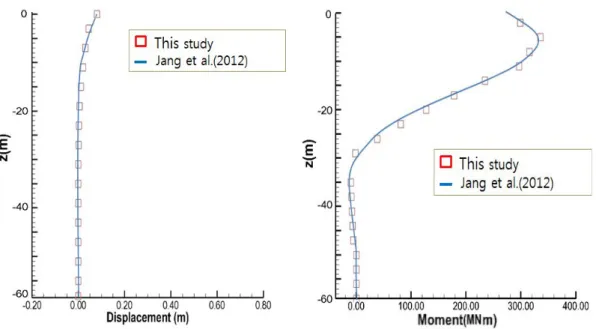
The behavior of the offshore wind tower foundation embedded in sandy soil was analyzed by Jang et al. (2013). For analysis of this study, soil conditions are considered as all sandy soils. The embedded depth and are 60m and 16,300 , respectively. The height of tower and the embedded depth are 90m and 60m, respectively (Fig. 3 and Table 3).
For verification, calculation is carried out with same condition from Jang et al. (2013). The Fig. 4 shows the comparison of this study from the results of Jang et al. (2013). The comparison also shows good agreement between this study and the results of Jang et al. (2013).
Examining the results of the verification, which shows that maximum displacement occurred in pile head. Also, moments are reduced from bottom to half of foundation
and are increased from half to top.
Fig. 3 Simple model of offshore wind turbine and forces in Jang al.(2013) Table 3. Structural properties of wind turbine model
Model Property Calibrated Values
Elastic modulus of tower structure (N/m2) 2.1 * 1011
External diameter of tower structure (m) 5
Wall thickness of tower structure (m) 0.06
Height of tower structure above the seabed (m) 8.76 * 10
Mass density of tower (kN/m3) 7.7 * 103
Mass of nacelle (kg) 2.4 * 105
CHAPTER 4
Application
For the application of the analysis, foundation of the offshore wind tower is computed using the p-y relation. These are performed for three types of soil condition. One of these is a cohesive soil condition and another is sandy soil condition, and the other is multi-layered soil condition.
4.1 Calculation of External Force
Various external forces act on offshore wind tower owing to wind velocity. Wind velocities influence on external forces such as wind force, wave force, and thrust force. Therefore, external forces according to wind velocities should be computed to examine effect of the soil condition.
In this study, wind velocities of 10m/s, 20m/s, and 30m/s are used to determine external forces, which are divided in order to confirm the effect of rotating blade.
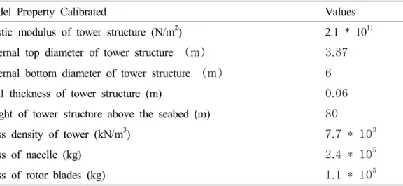
The top diameters of offshore wind tower is 3.87m. The bottom diameter, height, and water depth are 6m, 80m, and 30m respectively. The diameter of the tower is constantly decreased. The generator is 5MW NREL. Fig. 5 and Table 4 show condition of calculation condition.
Fig. 5 The simple model of calculation condition
Table 4. Structural properties of wind turbine model
Model Property Calibrated Values
Elastic modulus of tower structure (N/m2) 2.1 * 1011 External top diameter of tower structure (m) 3.87 External bottom diameter of tower structure (m) 6
Wall thickness of tower structure (m) 0.06
Height of tower structure above the seabed (m) 80
Mass density of tower (kN/m3) 7.7 * 103
Mass of nacelle (kg) 2.4 * 105
Mass of rotor blades (kg) 1.1 * 105
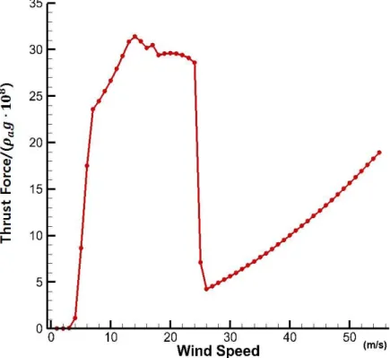
Fig. 6 shows the thrust force. The thrust force is increased rapidly between 4m/s and 7m/s, which is cut-in wind velocity of the wind turbine. This is due to the fact
that the optimal TSR (Tip Speed Ratio) of the designed wind turbine is set to 10 after the 7m/s wind velocity. The thrust force is decreased in over the 15m/s wind velocity because the pitch angle of the blade is changed to the optimal pitch angle to keep safety load. if wind blow over the 25m/s wind velocity, the thrust force of blade is decreased rapidly, which is due to the fact that the wind turbine is stopped the operation in over cut-out wind velocity. After cut-out wind velocity, the thrust force of blade is influenced by only wind.
Fig. 6 Thrust force of the designed blade
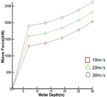
Fig. 7 shows the wind force acting on offshore wind tower according to wind velocities, which shows that wind force is increased according to wind velocity. However, part of wind force acting on the offshore wind tower is decreased by loss of blade tip when the blade rotates.
sea surface, because maximum water particles speed occurred in the mean sea surface.
Fig. 7 Wind forces acting on the offshore wind tower according to wind velocities
4.2 Calculation of Foundation
In order to examine effect of the soil condition, foundation of offshore wind tower embedded in variation soil conditions such as cohesive soil, sandy soil, and multi-layered soil are analyzed.
4.2.1 Calculation of Foundation in cohesive soil
To examine effect of the soil condition, the tendency for the behavior in single-layered soils should be researched. The soil condition of cohesive soil is the same as the study of Andersen et al.(2012). Figs. 9~12 show the calculation results.
shear force and Fig. 12 shows the moment. Table 2 shows the values of the results.
Fig. 10 Subsoil reaction in cohesive soil
Fig. 12 Moment in cohesive soil
Table 4. Maximum values of response in cohesive soil according to wind velocities Wind velocity 10m/s 20m/s 30m/s Maximum displacement (m) 0.005 0.02 0.05 Maximum subsoil reaction (MN/m) 0.13 0.17 0.2 Maximum shear force (MN) 0.8 2.5 3.9
4.2.2 Calculation of Foundation in Sandy Soil
The case of sandy soil is calculated for comparison with cohesive soil. Figs. 13~16 show the results of calculation and Table 3 shows the maximum values of the results.
Fig. 16 Moment in sandy soil
Table 5. Maximum values of response in sandy soil wind velocity 10m/s 20m/s 30m/s Maximum displacement (m) 0.003 0.006 0.01 Maximum subsoil reaction (MN/m) 0.24 1.1 1.3 Maximum shear force (MN) 3.7 6 9 Maximum moment (MNm) 68 148 224
4.2.3 Calculation of Foundation in Multi-layered Soil
For comparison with single-soils, the case of multi-layered soil is calculated. The sandy soil condition and the cohesive soil condition are the same with the study of Jang et al. (2013) and Andersen et al. (2012) respectively. However the used nodes are not the same of Jang et al. (2013) and Andersen et al. (2012). In this study, the depth of sandy soil and cohesive soil are 15m and 15m, respectively. Figs. 17~20 show the results of calculation and Table 4 shows the maximum values of results.
Fig. 18 Subsoil reaction in multi-layered soil
Fig. 20 Moment in multi-layered soil
Table 6. Maximum values of response in multi-layered soil wind velocity 10m/s 20m/s 30m/s Maximum displacement (m) 0.002 0.009 0.019 Maximum subsoil reaction (MN/m) 0.1 0.17 0.28 Maximum shear force (MN) 1.2 3.2 5
CHAPTER 5
Conclusions and Remarks
5.1 Conclusions and Remarks
Using the p-y relation, this study is carried out to investigate the subsoil reaction acting on the foundation of the offshore wind tower according to external forces. In this study, p-y curves of Matlock (1970) in study of Andersen et al. (2012) and Reese et al.(1974) in study of Jang et al. (2013) are used in cohesive soil and sandy soil respectively. Analysis is performed for the external forces acting on the offshore wind tower, which is installed at a water depth of 30m and has a height of 80m above the mean sea surface and an embedded depth of 30m.
The results of this study are as in the following.
(1) To verify the foundation in cohesive soil, the results from the verification model are compared with those computed by Andersen et al. (2012). The comparisons show good agreement among these models. To verify in sandy soil, the results from the verification model are compared with those computed by Jang et al. (2013). In case of cohesive soil, maximum displacement occurred in pile head and subsoil reactions are reduced from bottom to half of foundation and are increased from half to top. In case of sandy soil, maximum displacement occurred in pile head. Also, moments are reduced from bottom to half of foundation and are increased from half to top. The comparisons show good agreement among these models.
well as, the maximum subsoil reaction, shear force, and moment occurred in sandy soil. This might be due to the fact that the subsoil strength dominate interaction between the structure and subsoil.
(3) The results reveal the external forces acting on the offshore tower are rapidly increased beyond a range of the rotor operation. This is due to the fact that the wind force acting on the offshore tower is decreased by interference effect according to the rotor revolution.
(4) In multi-layered soil, it shows that sandy soil endures almost load. This is due to the fact that the sandy soil is stronger than cohesive soil.
5.2 Future Works
The study fields, which need to be conduct in future, are listed below.
1. The present study does not include the dynamics. In reality, the loads acting on offshore wind tower are the dynamic and behavior of offshore wind tower is also dynamic. In further study, dynamic characteristics for accurate analysis of offshore wind tower should be analyzed.
2. In reality, all phenomena such as wind velocities, loads and stiffness of structure have probability distribution. In order to conduct quantitative analysis, reliability analysis is necessary.
3. Many structures are destroyed by fatigue failure according to cyclic load. Therefore, fatigue failure will be analyzed by dynamic analysis.
References
Andersen, L.V., Vahdatirad, M.J., Sichani, M.T., Sorensen, J.D.(2012), Matural frequencies of wind turbines on mono-pile foundations in clayey soils-A probabilistic approach, Computers and Geotechnics. 43 1-11
Coastal Development institute of Technology, 2011. Offshore Wind Power Generation
technical manual. Coastal Development Institute of Technology, Japan.(in Japan)
Gaudiosi. G.(1999), Offshore Wind Energy Prospects, Renewable Energy. 16(2) 828-834.
Iguchi, T., Sekita, K., Yamamoto, K. and Morita, Y.(2000), A Feasibility Study on Advantage of Offshore Wind Turbine, JSCE Journal of Japan Society of Civil
Engineers, 16, 141-146.(in Japan)
Jang, H.S., Kim, H.S., Kwak, Y.M. and Park, J.H.(2013), Analysis of Lateral Behavior of Offshore Wind Turbine mono-pile Foundation in Sandy Soil, Journal
of Korean Society of Steel Construction, Vol. 25, No. 4, pp. 421-430.(in Korean)
Kim, N.H and Cao, T.N.T.(2008), Wave force analysis of the two vertical cylinders by boundary element method, KSCE Journal of Civil Engineering, 12(6), 359-366.
Kim, N.H. and Jin, J.W.(2010), Assessment of Wind Energy Potential around Jeju Coastal Area, KSCE Journal of the Korean Society of Civil Engineers, 30(6), 617-625.(in Korean)
Kim, N.H. and Jin, J.W.(2013), Sensitivity Analysis of Offshore Wind Turbine Tower Caused by the External Force, KSCE Journal of Civil Engineering, 17(5), 859-864.
Kim, N.H., Park, M.S. and Yang, S.B.(2007), Wave force analysis of the vertical circular cylinder by boundary element method, KSCE Jounal of Civil Engineering, 11(1), 31-35.
Kyoung, N.H., Yoon, J.E., Jang, M.S. and Jang, D.S.(2003), An Assessment of Offshore Wind Energy Resources around Korean Peninsula, Jounal of the Korean
Solar Energy Society, 23(2), 35-41.(in Korean)
Lee, S.H., Kim, S.R., Lee, J.H. and Chung, M.K.(2011), Evaluation of p-y Curves of Poles in Soft Deposits by 3-Dimensional Numerical Analysis, Journal of the
Korean Geotechnical Society, 27(7), 47-57.(in Korean)
Nagai, T., Suzuki, K., Ushiyama, Y., Hosomi, M., Ogawa, R. and Noguchi, H.( 2008), Development of Medium Size Wind Power System and its Application to Coastal Areas. ISSN 1346-7540, Port and Airport Research Institute.(in Japan) Nah, D.B., Shin, H.S. and Nah, D.J.(2011), Offshore Wind Power. Review, Journal
of Energy Engineering, 20(2), 143-153.(in Korean)
Nakamura, S., Sekita, K., Yamashita, A. and Hayashi. N.(2002), Study on the Vibration Response to Winds and Waves of Offshore Wind Turbines. JSCE
감사의 글
감사의 글을 적기 위해선 지난 2년간 아낌없는 조언과 끊임없는 관심을 통한 진심어린 지도로 석사 과정을 무사히 마칠 수 있게 이끌어 주신 김남형 교수님 에 대한 감사의 마음을 전하는 것이 무엇보다 우선이라고 생각됩니다.밤낮을 가 리지 않고 솔선수범 하시며 공부하시는 교수님이 계셨기에 2년간 분발하며 이 과정을 마칠 수 있었습니다.교수님께는 감사한 마음뿐이며 언제나 건강하시길 바랍니다.또한 바쁘신 와중에도 심사를 맡으셔서 세심한 지도를 해 주신 허영택 박사님과 박민수 박사님께도 진심으로 감사를 드립니다.아울러 학부과정을 비롯 해 대학원을 마치는 동안 많은 가르침을 주신 양성기 교수님,이병걸 교수님,박 상렬 교수님,김상진 교수님,이동욱 교수님께도 감사드립니다. 학부 시절부터 대학원을 마칠 때까지 여러 가지 조언을 해주며 생활하며 생각 지 못했던 점들을 돌이킬 수 있게 해준 수민이형과 꾸준함과 성실함을 배울 수 있었던 현진이형에게 감사함을 전합니다.힘든 일이 있을 때마다 숨김없이 얘기 하고 관심을 쏟아주던 형들이 있었기에 대학원 생활을 무사히 마칠 수 있었습니 다. 연구를 하는 동안 항상 새로운 방향으로 생각할 수 있도록 관심과 조언을 아 끼지 않으셨던 순보 형에게도 감사한 마음을 전합니다.헤매며 나아가지 못 할 때 해주신 한 마디 한 마디 덕분에 길을 잃지 않을 수 있었습니다. 유학의 꿈을 꾸며 목표가 되어주신 경보형,행식이형,향혜누나,지원이누나, 승현이형 그리고 철없는 후배를 동생처럼 아끼며 이끌어주신 현철이형,창림이 형,정운이형과 같은 나이이지만 먼저 대학원 생활을 겪으며 조언을 해준 주경 이,서리에게도 감사할 따름입니다. 그리고 다른 연구실이었지만 대학원 생활을 하며 의지가 되어준,우열이형,경태형,창선이형,원석이형,용석이형,준호형,도한이형과 풍력대학원에서 공부 중 인 동협이형,서정이,지선이등 모두에게 좋은 결과가 있길 바랍니다. 그리고 지금은 다른 대학에서 대학원을 마치는 정윤이와 민재에게도 고맙단 말을 전하고 싶습니다.오랜 친구들이지만 더 어른스럽고 더 꿋꿋이 2년을 보내 며 고민,걱정을 들어주며 서로 공감할 수 있는 친구가 있어서 힘을 낼 수 있었 습니다. 마지막으로,장남임에도 집안일을 신경 쓰지 못하는 저를 믿고 지켜봐 주시면 서 용기를 주셨던 너무나도 사랑하며 존경하는 부모님과 한창 열심히 공부 중인 동생에게 감사의 글을 빌어 제 마음을 전합니다.항상 고맙고 사랑합니다.언제 나 건강하길 바랍니다. 2014년 2월
List of Papers
◈
Refereed Journal Paper
① “Analysis of the Multi-layered Soil on mono-pile Foundation of Offshore Wind Turbine” J. Navig. Port Res. Vol. 37, No. 6, pp. 653-660, 2013(in Korean).
◈
Proceedings of Annual Conference
① “Boundary Numerical Analysis of Waves coming with Oblique Angle to Submerged Breakwater on the Porous Seabed” Proceeding of the Korean Institute
of Navigation and Port Research, pp. 11-12, 2012(in Korean).
② “Estimation of the Stability of Maza-type Artificial Reef” Proceeding of the
Korean Annual Conference on Civil Engineering, pp. 2118-2121, 2012(in Korean).
③ “Numerical Analysis of the Wind and Wave Force according to the Shape Change of Offshore Wind Turbine Tower” Proceeding of the Korean Annual
Conference on Civil Engineering, pp. 2134-2137, 2012(in Korean).
④ “Analysis of Wind and Wave Force acting on the Foundation of the Offshore Wind Tower” Proceeding of the Korean Institute of Navigation and Port Research, pp. 273-274, 2013(in Korean).
⑤ “Analysis of Subgrade Reaction acting on the mono-pile Foundation of Offshore Wind Tower” Proceeding of the Korean Annual Conference on Civil Engineering, pp. 942-946, 2013.
◈