Thermostability of Monolithic and Reinforced
Al–Fe–V–Si Materials
Yiqiang Hea
, Bin Qiaoa
, Na Wangb,∗, Jianming Yanga
, Zhengkun Xuc
,
Zhenhua Chend
and Zhigang Chend a
College of Mechanical Engineering, Huaihai Institute of Technology, Lianyungang 222005, People’s Republic of China
b
Department of Human Resources, Huaihai Institute of Technology, Lianyungang 222005, People’s Republic of China
c
Department of Mechanical Engineering, Zhangjiajie Institute of Aviation Industry vocational, Zhangjiajie, Hunan 427000, People’s Republic of China
d
College of Materials Science and Engineering, Hunan University, Changsha 410082, People’s Republic of China
Received 5 November 2007; accepted 4 November 2008
Abstract
Al–Fe–V–Si alloys reinforced with SiC particles were prepared by multi-layer spray deposition technique. Both microstructures and mechanical properties including hardness and tensile properties development during hot exposure process of Al–8.5Fe–1.3V–1.7Si, Al–8.5Fe–1.3V–1.7Si/15 vol% SiCPand Al–10.0Fe–
1.3V–2Si/15 vol% SiCPwere investigated. The experimental results showed that an amorphous interface of
about 3 nm in thickness formed between SiC particles and the matrix. SiC particles injected silicon into the matrix; thus an elevated silicon concentration was found around α-Al12(Fe, V)3Si dispersoids, which
subse-quently inhibited the coarsening and decomposition of α-Al12(Fe, V)3Si dispersoids and enhanced the
ther-mostability of the alloy matrix. Moreover, the therther-mostability of microstructure and mechanical properties of Al–10.0Fe–1.3V–2Si/15 vol% SiCPare of higher quality than those of Al–8.5Fe–1.3V–1.7Si/15 vol% SiCP. ©Koninklijke Brill NV, Leiden, 2009
Keywords
Metal–matrix composites, heat resistant aluminum alloy, annealing, thermostability
1. Introduction
Early in 1986, an Al–Fe–V–Si system heat resistant aluminum alloy was developed by Skinner et al. of Allied-Signal Corp., which can be applied at a temperature up to 400◦C [1]. The combination of spray deposition technology and reinforcement with added ceramic particulate is a powerful tool for developing high performance
*To whom correspondence should be addressed. E-mail: [email protected]
Edited by JSCM and KSCM
metallic materials with enhanced strength and stiffness, wear resistance, stability of properties at elevated temperature and reduced density [2–4]. Generally, light alloys are limited by their poor thermostability at temperatures above 0.6Tm [5].
The Al–Fe–V–Si alloy has been reported to be a material that displays an attractive combination of density, room and high temperature strengths, ductility, and fracture toughness [6, 7]. The microstructure of rapid solidified Al–Fe–V–Si alloy consists of α-Al matrix and near-spherical silicide particles with high volume fraction. Sili-cide particles disperse evenly throughout the α-Al matrix, which contributes to the excellent ambient temperature and elevated temperature mechanical properties of the alloy. However, a rapid cooling rate is needed to ensure the high mechanical properties of this kind of material, and it has been shown that a slower cooling rate usually leads to a coarse primary intermetallic phase, a quasicrystal phase, and cel-lular microstructure which proved to be harmful to mechanical properties [8–10]. Therefore, it is necessary to investigate the microstructure evolution at elevated temperature.
The thermostability of ultrafine grain structure, dispersoids and mechanical prop-erties of spray deposited Al–8.5Fe–1.3V–1.7Si/SiCP during hot work was
investi-gated in our earlier work [11]. Yaneva et al. studied the structure development of microcrystalline Al–8.5Fe–1.06V–2.75Si ribbons during reheating in temperature range from room temperature to 600◦C [6]. Hambleton et al. reported on the ef-fects of reinforcement with 20 wt% SiC on the response to thermal exposure at 425◦C and 550◦C of rapidly solidified Al–8.3Fe–1.3V–1.7Si alloy [5]. In previ-ous work, researchers emphasized the microstructure development of the rapidly solidification/powder metallurgy (RS/PM) Al–Fe–V–Si alloys. Pioneering work on synthesis of metal matrix composites using spray deposition (SD) was done by the group of Lavernia and co-workers, including the effects of ceramic reinforcement on residual stresses [12], modeling of porosity [13], and mechanical properties [14]. But thermostability of SD Al–Fe–V–Si alloys has been studied rarely, and few in-vestigations concerning Al–Fe–V–Si/SiCPof different matrix alloy composition in
a broad temperature range have been reported.
The purpose of the present work is to report the effects of various matrix al-loy composition and reinforcement with 15 vol% SiC particles on the response to thermal exposure at temperature ranging from 250◦C to 630◦C of spray deposited Al–8.5Fe–1.3V–1.7Si and Al–10.0Fe–1.3V–2.0Si alloys.
2. Experimental
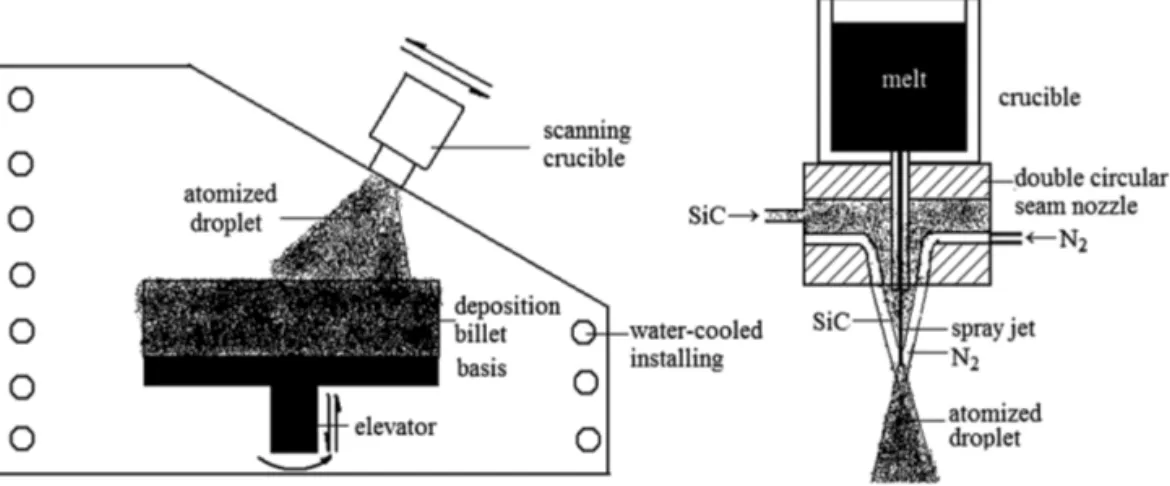
The nominal compositions of Al–Fe–V–Si alloy in this study are Al–8.5Fe–1.3V– 1.7Si and Al–10.0Fe–1.3V–2.0Si. SiC particles with a volume fraction of 15% and mean size of about 10 µm are selected as the reinforcement phase. The composite preforms were firstly fabricated by a self-developed spray deposition equipment with crucible scanning (Fig. 1).
The relative density of the as-deposited preforms was 88.9% as measured by Archimedes’ method. Hot pressing was used for densification of the composite
pre-Figure 1. Spray deposition equipment of crucible scan.
forms. The as-deposited preforms were prepared in the form of cylinders with the size of 300 mm in diameter and 400 mm in height, and then were turned into cylin-ders of 155 mm in diameter before hot working. The as-turned billets were heated up to 450◦C and this was followed by hot pressing to a column with the diameter of 165 mm. The hot pressing die was heated up to 410◦C. The as-pressed columns were turned to 155 mm in diameter and were submitted to the step mentioned above for a second pressing. Then the billets as secondarily pressed were cut into plates for the next rolling with their planes vertical to the pressing direction.
Before hot rolling, the plates were heated at the given temperature (490◦C) for 1 h. The pass reduction was about 10%. The plates were heated for 10 min/pass. The obtained Al–8.5Fe–1.3V–1.7Si/SiCP composite sheets were 0.6–0.8 mm in
thick-ness.
The as-rolled sheets after hot-pressing of Al–8.5Fe–1.3V–1.7Si, Al–8.5Fe–1.3V– 1.7Si/15 vol% SiCP and Al–10.0Fe–1.3V–2Si/15 vol% SiCP were annealed at
250◦C, 350◦C, 450◦C, 500◦C, and 550◦C for 1, 3, 5, 10, 20, 50, 70, 100, 150, 200 h, and at 600◦C and 630◦C for 1, 2, 3, 4, 5, 6, 7, 8, 9, 10 h, respectively.
Hardness measurements were conducted on a Brinell hardness tester with a load of 1500 kgf. Sheet samples with 20 mm in thickness were taken for hardness mea-surement. The reported values are the averages of 5 measurements.
Microstructure characterization was carried out on a JEOL 200CX prototype transmission electron microscopy (TEM) operating at 100 kV and a JEOL 3010 prototype high resolution transmission electron microscopy (HRTEM) operating at 300 kV. The silicon concentration in the matrix was measured by a energy disper-sive X-ray detector (EDX). Thin foils for HRTEM and EDX were mechanically and chemically thinned. These foils were prepared from the unreinforced alloy and the reinforced composites, respectively, by punching out 3 mm discs, followed by grinding with abrasive papers into a thickness of about 100 µm. Adopting a double jet technique, these discs were electrochemically polished in a solution of 25% ni-tric acid in methanol at−25◦C to∼20 µm with a 0.25 µm finish. Ion beam thinning
was then carried out on a Gatan PIPSTM operating at 4.5 keV, 11 µA and 3◦ inci-dence angle. Discs that were nanoscale in thickness were obtained, and then used for HRTEM and EDX.
3. Results
3.1. Microstructures
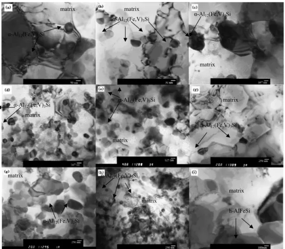
The microstructure of the alloy evolved to different extents during annealing at high temperature, as well as the composite. Figure 2 shows the microstructure develop-ment of the materials during the annealing process; the sizes of α-Al12(Fe, V)3Si
dispersoids in the samples during annealing at different temperatures are listed in Table 1. As indicated in Fig. 2, the microstructures of both the alloy and composite
Figure 2. Microstructure evolution of Al–Fe–V–Si alloy and composites annealing at different
temperatures: (a) Al–8.5Fe–1.3V–1.7Si/15 vol% SiCP; (b) Al–10Fe–1.3V–2.0Si/15 vol% SiCP;
(c) Al–8.5Fe–1.3V–1.7Si; (d) Al–8.5Fe–1.3V–1.7Si/15 vol% SiCPunannealed; (e) Al–10Fe–1.3V–
2.0Si/15 vol% SiCP; (f) Al–8.5Fe–1.3V–1.7Si annealing at 550◦C for 200 h; (g) Al–8.5Fe–
1.3V–1.7Si/15 vol% SiCP; (h) Al–10Fe–1.3V–2.0Si/15 vol% SiCP; (i) Al–8.5Fe–1.3V–1.7Si at 600◦C
Table 1.
The dispersoid sizes of the materials during annealing
Materials Sizes of Sizes of dispersoids Sizes of dispersoids dispersoids annealed at 550◦C annealed at 600◦C unannealed for 200 h for 10 h
(nm) (nm) (nm)
Al–8.5Fe–1.3V–1.7Si/15 vol% SiCP 30–80 100 200–300
Al–10.0Fe–1.3V–2.0Si/15 vol% SiCP 30–80 80 100–150
Al–8.5Fe–1.3V–1.7Si 300 350 500
samples exhibited remarkable thermostability: dispersoids in the matrix retained a nearly spherical shape during thermal exposure even after 200 h at 550◦C. It can be seen from Fig. 2(a) and 2(b) that the size of the α-Al12(Fe, V)3Si dispersoids in the
unannealed composite sample is between 30 and 80 nm, and the dispersoids distrib-ute in the grains and along the grain boundaries. The size of the dispersoids is about 300 nm in the unreinforced alloy shown in Fig. 2(c), which is much coarser than that in the unannealed composite samples. The dispersoids in Al–10.0Fe–1.3V– 2.0Si/15 vol% SiCP grew little after exposure at 550◦C for 200 h as shown in
Fig. 2(e), while the dispersoids in Al–8.5Fe–1.3V–1.7Si/15 vol% SiCPgrew slightly
to about 100 nm (Fig. 2(d)). It is worth noticing that few dislocations can be ob-served in the composites exposed at 550◦C for 200 h. For the Al–8.5Fe–1.3V–1.7Si alloy annealed at 550◦C for 200 h shown in Fig. 2(f), both the dispersoids and the grains grew to a certain degree. When the sample was treated at 600◦C for 10 h, obvious differences in microstructure appeared, as shown in Fig. 2(g). The disper-soids in the Al–8.5Fe–1.3V–1.7Si/15 vol% SiCPcomposite grew to 200–300 nm in
diameter, which was larger than that in the Al–10.0Fe–1.3V–2.0Si/15 vol% SiCP
composite sample shown in Fig. 2(h). Some coarse phases which were harmful to the mechanical properties appeared in the alloy without SiC particle reinforce-ment under the same conditions (Fig. 2(i)). Moreover, a polygon-like phase arises in Fig. 2(i), and this secondary phase is identified as a compound with hexagonal parameters a= 2.514 nm and c = 1.257 nm, which is in agreement with the phe-nomenon observed by Wang et al. [15] in spray deposited Al–8.5Fe–1.1V–1.9Si alloy. The dispersoids assembled and grew obviously.
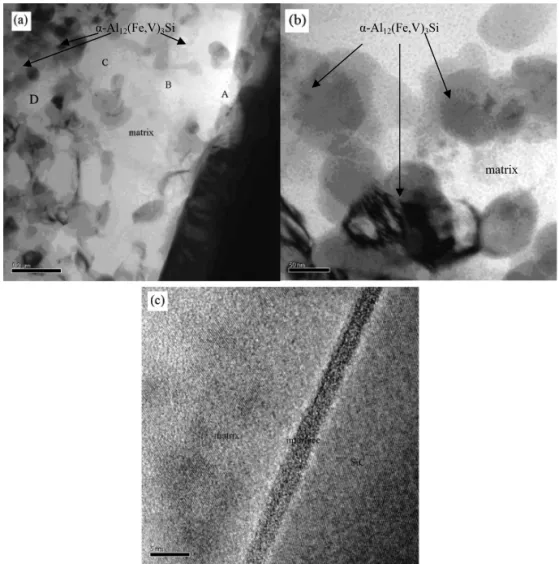
Considering the effects of SiC particles on the microstructure of alloy matrix, it is necessary to determine the microstructures of the SiC–matrix interface. Figure 3(a) shows the morphology of the SiC–matrix interface and the distribution of the α-Al12(Fe, V)3Si dispersoids. It was found that the dispersoids distribute relatively
uniformly in the matrix (Fig. 3(a)), and the size is about 50 nm. Nanocrystalline particles can be seen from Fig. 3(b), which formed in a transition region (200– 400 nm in width) near the SiC particle boundary in matrix. Figure 3(c) gives the high resolution images of an amorphous interface of 2.5–3 nm in width between
Figure 3. HRTEM micrographs of the SiC–matrix interface in the as-rolled Al–8.5Fe–
1.3V–1.7Si/15 vol% SiCP: (a) morphology of the SiC–matrix interface and the distribution of the
dispersoids; (b) nanocrystalline particles in the matrix near the interface; (c) a high resolution image of the interface.
The amorphous interfacial was observed by Romero et al. [16] in the composite of 1100 Al and α-SiC. On the other hand, in Fig. 3(c), the high resolution images show some nanocrystalline particles (3–5 nm in diameter). Table 2 shows the obvious silicon concentration gradient measured by EDX in the matrix near the SiC–matrix interface; it may be seen that the silicon concentration falls from 30.13 at% at point A to 21.22 at% at point D in Fig. 3(a), which means partial dissolution of the SiC particle surface and interface reaction between the SiC particles and alloy matrix. 3.2. Mechanical Properties
Figure 4 presents the development of hardness of the three materials with annealing time during a temperature range from 250◦C to 630◦C. It can be seen from Fig. 4(a) to 4(c) that hardness of the materials with or without SiC particles annealed at
Table 2.
Si concentration at different points in matrix in Fig. 3(a) near the SiC–matrix interface
Position A B C D
Si concentration (at%) 30.13 28.39 25.32 21.22
(a) (b)
(c) (d)
Figure 4. Hardness evolution of Al–Fe–V–Si alloy and composites annealing at different temperatures
for different times: (a) 250◦C; (b) 350◦C; (c) 450◦C; (d) 500◦C; (e) 550◦C; (f) 600◦C; (g) 630◦C.
250◦C, 350◦C and 450◦C did not decline obviously with prolonged annealing time, and there was no visible difference among the three materials annealed at 450◦C (with the exception of annealing for 200 h at 450◦C). As annealing temperature elevated, hardness distinction between the alloy and the composites became evident (Fig. 4(d–g)). Hardness of the alloy dropped sharply after 50 h at 550◦C (Fig. 4(e)), while that of the composites maintained at a high level. What is worth noticing is that the hardness of Al–10.0Fe–1.3V–2.0Si/15 vol% SiCPremained at a higher level
than that of Al–8.5Fe–1.3V–1.7Si/15 vol% SiCP when they were each annealed
(e) (f)
(g)
Figure 4. (Continued.)
Figure 5. Hardness evolution of Al–Fe–V–Si alloy and composites annealing at different
tempera-tures: 250◦C, 350◦C, 450◦C, 500◦C, 550◦C, 600◦C, 630◦C for 10 h.
Figure 5 shows the hardness evolution of the Al–Fe–V–Si alloy and compos-ites annealed at different temperatures. It is clear that hardness of the composcompos-ites remained at a higher level than that of the alloy when annealing temperature was above 450◦C; similarly, the hardness of Al–10.0Fe–1.3V–2.0Si/15 vol% SiCPwas
Table 3.
Tensile properties of Al–Fe–V–Si alloy and composites exposed at 550◦C for 200 h Condition
Material
Test temperature/
◦C
As-rolled Exposed at 550◦C for 200 h
σb(MPa) σ0.2(MPa) δ (%) σb(MPa) σ0.2(MPa) δ (%) Al–8.5Fe–1.3V–1.7Si 25 470.0 320.0 9.6 396.7 304.0 5.2 315 250.0 200.0 11.2 202.5 164.0 7.8 400 165.0 130.0 14.0 144.0 113.0 8.6 Al–8.5Fe–1.3V–1.7Si/ 25 580.0 525.0 6.3 545.0 515.0 5.5 15 vol% SiCP 315 285.0 245.0 3.5 267.3 239.5 3.4 400 186.0 150.0 2.5 172.4 143.2 2.4 Al–10.0Fe–1.3V–2.0Si/ 25 533.1 367.2 5.6 502.2 435.0 4.7 15 vol% SiCP 315 306.4 266.1 4.6 296.9 273.4 4.1 400 207.5 149.2 2.7 188.5 152.3 2.1
relatively higher than that of Al–8.5Fe–1.3V–1.7Si/15 vol% SiCP when the
com-posites annealed at temperature above 450◦C.
Evolution of the yield strength and tensile strength at elevated temperature is very important to clarify in view of the thermal resistance of the materials. Table 3 presents evolution of tensile properties of the three materials before and after expo-sure at 550◦C for 200 h. It is found that decreasing of the tensile properties both at ambient and elevated temperature of Al–8.5Fe–1.3V–1.7Si/15 vol% SiCPis much
lighter than that of Al–8.5Fe–1.3V–1.7Si when they are exposed at 550◦C for 200 h. Furthermore, reduction of the tensile properties of Al–10.0Fe–1.3V–2.0Si/15 vol% SiCP is slighter than that of Al–8.5Fe–1.3V–1.7Si/15 vol% SiCP. It is thus shown
that the tensile property development of the three materials with annealing temper-ature is in agreement with the hardness evolution.
4. Discussion
Nearly spherical body-centered cubic α-Al12(Fe, V)3Si dispersoids with high
vol-ume fraction (typical 27–36%) and small size (50–10 nm) usually result from the high cooling rate (up to 103–104 K/s) of spray deposition processing, the lattice parameter of which is about two times larger than that of the α-Al matrix (range from 1.25 nm to 1.26 nm). These dispersoids are characterized with considerable low coarsening rate because of the larger lattice parameter, which contributes to the excellent thermostability of the alloy regardless of reinforcement.
The low diffusion rates of Fe, V in the matrix can ensure the stability of the dis-persoids at elevated temperature. The disdis-persoids can lock the dislocations, pin up the grain boundary and restrain the recrystallization, and consequently can improve the elevated temperature mechanical properties of Al–F–V–Si alloys. Spray depo-sition processing provides a high cooling rate for the as-atomized alloy droplets, characterized with segregation reduction, grain refinement, solid solubility
eleva-tion and fine metastable phase precipitaeleva-tion, which results in excellent thermosta-bility of the alloy and the composites.
Strength of dispersion-strengthened alloy lies not only in inherent character of the matrix and dispersed phase, but also depends on the volume fraction, distribu-tion, size, shape, and the bonding state between the dispersed phase and the matrix. According to alloying strengthening theory, decrease of the strength at elevated temperature can be attributed to several factors as follows: crystallization soften-ing, rapid diffusion of solute atoms, coarsening of the dispersed phase, dislocation climb and crystal boundary migration.
Coarsening of the dispersoids is the key factor in the aspects mentioned above; the relationship between the strength and volume fraction and size of dispersoids can be expressed as:
σ0.2∝V 3/2 f
r , (1)
where r is the radius of the dispersoid particles, σ0.2 represents the yield strength
of the alloy, and Vfis the volume fraction of the dispersed phase.
The dispersoids in Al–8.5Fe–1.3V–1.7Si alloy without reinforcement were much coarser than its composites and of Al–10.0Fe–1.3V–2.0Si/15 vol% SiCP(Fig. 1(a–
c)). The nearly spherical dispersoids (α-Al12(Fe, V)3Si) usually transformed into
coarse phases (typically θ -Al13Fe4 or h-AlFeSi) after 10 h at 600◦C, which would
deteriorate the mechanical properties of the materials. As a result, hardness and tensile properties of the alloy decreased sharply after 10 h at 600◦C in this study.
As is mentioned above, the high cooling rate (103–104K/s) of multi-layer spray deposition insured fine microstructure, and the co-deposition of SiC particles in-creased the cooling rate of the droplets, which can refine the grain size of the alloy matrix and the dispersion phase α-Al12(Fe, V)3Si particle and increase its volume
fraction.
Addition of SiC can elevate the cooling rate of the atomized droplets when SiC particles diffused into the droplets. As a result, dispersoids of higher volume frac-tion (Vf) became finer (lower r value). Additionally, SiC particles reacted with Al
matrix to form an amorphous interface of 2.5–3 nm in width, and SiC particles in-jected silicon into the matrix, which resulted in a higher silicon concentration in the matrix (as shown in Table 2). The elevation of silicon concentration around
α-Al12(Fe, V)3Si dispersoids prevented the dispersoids from coarsening and
trans-forming into θ -Al13Fe4, which played a role of stabilization of the dispersoids
(α-Al12(Fe, V)3Si) with low r value.
Compared with those of the alloy unreinforced, the α-Al12(Fe, V)3Si
disper-soids of the composites remained finer and more dispersed during the annealing process. According to (1), yield strength σ0.2 elevates when r decreases and Vf
in-creases. Moreover, finer dispersoids penned up the grain boundary and restrained the recrystallization more effectively. Therefore, a much higher thermostability of the composites of Al–8.5Fe–1.3V–1.7Si/15 vol% SiCP and Al–10.0Fe–1.3V–
2.0Si/15 vol% SiCP compared with that of Al–8.5Fe–1.3V–1.7Si alloy was
ob-tained. The microstructure including α-Al12(Fe, V)3Si dispersoids and grains of
Al–10.0Fe–1.3V–2.0Si/15 vol% SiCPpresented a greater thermostability than that
of Al–8.5Fe–1.3V–1.7Si/15 vol% SiCP, which may be attributed to the high volume
fraction of dispersoids that were restrained from growing. Consequently, hardness and tensile properties of Al–10.0Fe–1.3V– 2.0Si/15 vol% SiCP maintained at a
higher level than that of Al–8.5Fe–1.3V–1.7Si/15 vol% SiCPduring the annealing
process.
5. Conclusion
In the present work, the thermostability of microstructure, harness and tensile prop-erties of Al–8.5Fe–1.3V–1.7Si alloy, Al–8.5Fe–1.3V–1.7Si/15 vol% SiCPand Al–
10Fe–1.3V–2.0Si/15 vol% SiCPcomposites annealed at a temperature ranging from
250◦C to 630◦C were investigated. The main conclusions can be drawn as follows: (1) The Al–Fe–V–Si alloy and composites prepared by spray deposition processing can provide excellent thermostability: α-Al12(Fe, V)3Si dispersoids maintained
a nearly spherical shape with little growth even after 200 h at 550◦C.
(2) An amorphous SiC/Al interface of about 3 nm in thickness formed in the composite as-rolled. Nanocrystalline particles formed in a transition region (200–400 nm in width) near the SiC particle boundary in the matrix. A silicon concentration gradient in the matrix appeared near the SiC–matrix interface, which meant partial dissolution of the SiC particle surface.
(3) The addition of SiC particles leads to higher microstructure thermostability, which prevents the fine α-Al12(Fe, V)3Si dispersoids from coarsening,
decom-posing, and transforming into a coarser phase. Subsequently, finer dispersoids prevented the grains from coarsening and recrystallizing. All these contribute to thermostability of the mechanical properties of Al–Fe–V–Si/SiCP
compos-ite. Compared with that of Al–8.5Fe–1.3V–1.7Si alloy, the microstructures of Al–8.5Fe–1.3V–1.7Si/15 vol% SiCP and Al–10Fe–1.3V–2.0Si/15 vol% SiCP
exhibited higher thermostability at the temperature above 450◦C. This can be attributed to elevation of silicon concentration around particulates resulted from partial dissolution of SiCP. As a result, decreasing of the mechanical properties
of Al–8.5Fe–1.3V–1.7Si/15 vol% SiCP is much less severe than that of Al–
8.5Fe–1.3V–1.7Si.
(4) The microstructures and mechanical properties of Al–10Fe–1.3V–2.0Si/ 15 vol% SiCP remained more stable compared to that of Al–8.5Fe–1.3V–
1.7Si/15 vol% SiCPduring hot exposure, especially for annealing temperature
Acknowledgements
The research described in this publication was made possible by financial sup-port of the Natural Science Foundation of Jiangsu Colleges and Universities (No. 09KJD430001).
The authors would like to acknowledge the contribution of Prof. Gang Chen, Miss Wei Li, and Mr. Xianjue Yin of Hunan University to the research.
References
1. D. J. Skinner, R. L. Bye, D. Raybould and A. M. Brown, Dispersion strengthened Al–Fe–V–Si alloys, Scr. Metall. 20, 867–872 (1986).
2. S. Hariprasad, S. M. L. Sastry and K. L. Jerina, Deformation behavior of a rapidly solidified fine grained Al–8.5% Fe–1.2% V–1.7% Si alloy, Acta Mater. 44, 383–389 (1996).
3. S. K. Subhash, A. Lawley, M. J. Koczak and K. G. Kirk, Creep and microstructural stability of dispersion strengthened Al–Fe–V–Si–Er alloy, Mater. Sci. Engng A 167, 11–21 (1993).
4. U. Prakash, T. Raghu, A. A. Gokhale and S. V. Kamat, Microstructure and mechanical properties of RSP/M Al–Fe–V–Si and Al–Fe–Ce alloys, J. Mater. Sci. 34, 5061–5065 (1999).
5. R. Hambleton, H. Jones and W. M. Rainforth, Effect of alloy composition and reinforcement with silicon carbide on the microstructure and mechanical of three silicide dispersion strengthened aluminium alloys, Mater. Sci. Engng A 304–306, 524–528 (2001).
6. S. Yaneva, A. Kalkanlı, K. Petrov, R. Petrov, I. Y. Houbaert and S. Kassabov, Structure develop-ment in rapidly solidified Al–Fe–V–Si ribbons, Mater. Sci. Engng A 373, 90–98 (2004).
7. K. L. Sahoo, S. K. Das and B. S. Murty, Formation of novel microstructures in conventionally cast Al–Fe–V–Si alloys, Mater. Sci. Engng A 355, 193–200 (2003).
8. S. K. Guan, N. F. Shen, Y. L. Tang and H. Q. Hu, Sensitivity of microstructure to thermal history of melts in rapidly solidified Al–Fe–M–Si alloys, Acta Metall. Sinica 32, 823–828 (1996). 9. L. Q. Chen, N. F. Shen and G. X. Sun, Formation conditions of massive phases in rapidly solidified
Al–Fe–V–Si alloys, Acta Metall. Sinica 31, 295–299 (1995).
10. Y. F. Sun, G. S. Zhang and N. F. Shen, Effect of in situ TiC particles on the formation of clump-like phases in rapidly solidified Al–Fe–V–Si alloys, Acta Metall. Sinica 37, 1193–1197 (2001). 11. Z. H. Chen, Y. Q He., H. G. Yan, Z. G. Chen, X. J. Yin and G. Chen, Ambient temperature
mechanical properties of Al–8.3Fe–1.3V–1.7Si/SiCP composite, Mater. Sci. Engng A 460–461, 180–185 (2007).
12. S. Ho and E. J. Lavernia, The effect of ceramic reinforcement on residual stresses during spray atomization and co-deposition of metal matrix composites, Scripta Metall. 34, 1911–1918 (1996). 13. W. D. Cai and E. J. Lavernia, Modeling of porosity during spray forming, Mater. Sci. Engng A
8–12, 226–228 (1997).
14. Q. Xu, R. W. Hayes, W. H. Hunt, Jr. and E. J. Lavernia, Mechanical properties and fracture be-havior of layered 6061/SiCP composites produced by spray atomization and co-deposition, Acta
Mater. 47, 43–53 (1999).
15. F. Wang, B. H. Zhu, B. Q. Xiong, Y. A. Zhang, H. W. Liu and R. H. Zhang, An investigation on the microstructure and mechanical properties of spray-deposited Al–8.5Fe–1.1V–1.9Si alloy,
J. Mater. Pro. Tech. 183, 386–389 (2007).
16. J. C. Romero, L. Wang and R. J. Arsenault, Interfacial structure of a SiC/Al composite, Mater.