Waste Management and Treatment of Decommissioned
Radioactive Combustible Waste
B. Y. Min*, Y. J. Lee, G. S. Yun, K. W. Lee, and J. K. Moon
Korea Atomic Energy Research InstituteAbstract :A large quantity of radioactive waste was generated during the decommissioning of the KRR and UCF. The radioactive waste was packed into 200 liter drums and 4m3containers and these were temporarily stored onsite
until their final disposal in the national repository facility. Some of the releasable waste was freely released and utilized for non-nuclear industries. The combustible wastes were treated by the utilization of an incinerator with a capacity of on average 20 kg/hr.
Keywords: Waste Management, Decommissioning Waste, Volume Reduction, Incineration
1. INTRODUCTION
Decontamination and decommissioning (D&D) has become one of the most important nuclear industries in developed countries including the USA, UK, and France, where D&D for retired nuclear facilities has been carried out on a large scale. Large quantities of contaminated combustible waste have been generated from decommissioning projects. Contaminated combustible waste represents a considerable storage volume; it also brings significant cost as it must be maintained and monitored indefinitely in secure storage. The high cost of either disposal or storage requires that the volume of this material be minimized. Two decommissioning projects have been carried out due to the retiring of nuclear research facilities such as KRR-1 & KRR-2 and a uranium conversion plant (UCP). Particularly for the decommissioning of the UCP, most of the internal components and system piping have been dismantled and the building was refurbished for reuse as another type of experimental facility. Through the above two projects, decommissioning wastes were generated, as shown in Table 1. Through the decommissioning of the TRIGA MARK II and UCP, more than 55 tons of
radioactive combustible waste were generated [1]. Decommissioning waste can be divided into radioactive waste and releasable waste. In the case of the KRRs, the classification value is 0.4 Bq/g. The specific activity level of radioactive waste is more than 0.4 Bq/g and the specif-ic activity level of releasable waste is less than 0.4 Bq/g. A total of 295 tons of radioactive waste and 2,185 tons of releasable waste were generated. Prompt countermea-sures should be taken to deal with combustible wastes generated by decommissioning projects. For the purpose of volume reduction for decommissioned combustible wastes generated by the dismantling of retired Korea Research Reactors 1 & 2 (KRR-1 & 2) and the uranium conversion plant (UCP), incineration treatment technolo-gy has been selected for the treatment of metal and com-bustible wastes. Among the decommissioning waste, volume reduction of the combustible wastes through incineration has merits from the view point of decrease in the amount of waste to be disposed of; this reduction will result in a reduction of the disposal cost. Incinerationis generally accepted as a method of reduc-ing the volume of radioactive waste. Incineration tech-nology is an effective treatment method that contains hazardous chemicals as well as radioactive contamina-tion [2]. The incinerator burns the waste at high tempera-tures. Incineration of a mixture of chemically hazardous and radioactive materials, known as “mixed waste,” has two principal goals: to reduce the volume and to reduce the total chemical toxicity of the waste. Incineration
Received : July 31, 2013 ·Revised : September 02, 2013 ·Approved : September 11, 2013 *Corresponding Author : B. Y. Min
Korea Atomic Energy Research Institute Tel : +82-42-868-2644 E-mail : [email protected]
Daedeokdaero 989-111, Yuseong-gu, Daejeon 305-353, Republic of Korea
itself does not destroy the metals or reduce the radioac-tivity of the waste. The main purpose of the incineration of radioactive waste is to reduce the waste volume, since a large proportion consists of bulky items such as conta-minated paper, cloth, gloves, shoes, lumber, and plastic.
This paper covers the general facility operation of an oxygen -enriched incinerator for the treatment of decommissioning wastes generated from a decommissioning project, included in this study are off-gas monitoring, volume reduction ratio, and dioxin measurement.
2. FACILITY OPERATION
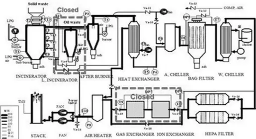
2.1 Facility DescriptionAn incineration facility was built to demonstrate the applicability of this technology to hazardous and low-level radioactive waste treatment from a nuclear facility. Fig. 1 shows a process diagram of Oxygen-Enriched Incineration (OEI). The system consists of a waste preparation system, incineration system, off-gas cooling system, and off-gas treatment system. The oil incinerator, gas exchanger, and ion exchanger equipment was closed during normal operation because decommissioning waste did not include oil and high chlorine content waste. Before the incineration, all wastes were classified manually. Organic waste and high chlorine content material were excluded from the incineration materials. The OEI was located at the KAERI site. The incineration facility, with a capacity of 25 kg of mixed waste per hour, was constructed in 1997. The system utilizes a confinement philosophy approach for radioactive and hazardous contamination control. The confinement philosophy con-sists of a combination of physical barriers and ventilation air control. The physical barriers are represented by the
surfaces of the system equipment. The incineration facility was operated by Korean Hydro & Nuclear Power (KHNP) until 2008 for performance tests and improvement, and for demonstration tests using RI waste. The demonstration incineration facility took over the responsibilities of KHNP for the decommissioned combustible waste. After taking over the demonstration incineration facility from KHNP, the facility was modified, and work toward the licensing procedure, and work on an extension of the object waste to include alpha-bearing waste and on increasing the incineration capacity began in June 2011. During the facility modification, the filter bank and the injection and transfer system were repaired. Incineration of object waste was extended to KEPCO NF and RI wastes. The operation license of the incineration facility was authorized by KINS in August 2011. The incineration facility has been in operation since that time. Ventilation control is represented by the controlled flow of air and gases from areas of least contamination potential to areas of greater contamination potential, with exit gases controlled using bag-filters, filter banks, ion exchangers, gas exchangers, and monitoring equipment. Special considerations have been incorporated into the design of the system for the treatment of problematic wastes. These problematic wastes can generally be described as heterogeneous wastes of varying physical descriptions, densities, and compositions, including all kinds of combustible and organic wastes and high chlorine content materials. Before the incineration, all wastes were classified manually. Organic waste and high chlorine content material were excluded from the incineration materials at KAERI.
An incinerator and afterburner are included in the incineration system. The incinerator was designed to have a single cylindrical chamber, a waste feeding unit, several combustion air inlets, and an ash collecting box. The inside diameter of the incinerator is 50 cm and the height is 122 cm. The size of the incinerator can be estimated using a mass balance equation with a proper
Concrete 268.9 (Release:1,735)1,855.6 310.0 3.7 Soil 52.6 - 2,505.2 Combustible 10.7 32.3 17.6 Non-combustible 22.6 84.8 17.6 Lagoon sludge - - 32.8 Total weight 395.0 2,185.0 2,950.5
residence time and a hydrodynamic consideration of the combustion in order to yield a capacity of 25 kg. A conical type incinerator bottom is connected to the ash box with a rotary valve. The incinerator has a sub burner for preheating and a main burner for incineration. Combustion air is blown into the incinerator through many small holes that are tangentially arranged. The OEI operates above 850°C. Most incinerators operate at higher temperature than the ignition temperature, which is the minimum temperature. The thermal destruction of most organic compounds occurs between 590°C to 650°C.
The purpose of the afterburner is to complete the com-bustion process that began in the incinerator, complete the combustion of any CO, and destroy VOCs in the off-gas leaving the incinerator. Gases leaving the incinerator pass and enter the afterburner, in which air and fuel are added to increase the gas temperature to 950°C. The afterburner is a refractory lined shell providing enough resistance time at sufficiently high temperature to destroy the organic compounds in the off-gas stream. The off-gas cooling system is composed of a heat exchanger and an air diluter. The off-gas cooling system is divided into two sections, hot and cold. The heat exchanger cools the gas from the afterburner rapidly to about 400°C by contacting the atmospheric temperature. Before the air diluter equipment, the temperature in the lines is above 400°C. In addition, the off-gas cooled down to less than 200°C when using the diluter for prop-er opprop-eration of the cold filtprop-ering units. The air dilutprop-er is a mixer of hot flue gas and cold ambient air. The exhaust gas is rapidly cooled to approximately 200°C. During waste processing, gases are produced in the incinerator. These gases are dependent on the waste composition and operating conditions. The gases may include water vapor, O2, CO, CO2, HCl, and volatile organic
com-pounds (VOCs) that are evaporated prior to their
destruction.
The off-gas treatment method is generally divided into wet and dry methods. KAERI’s off-gas system was adapted to create a dry system with air dilution and filtration. A bag filter and a set of high efficiency particulate air (HEPA) filters are arranged as the dry off-gas treatment units in the processing lines. Bag filters are used for dust removal during the incineration process. Bag filters are surface-type filters. Surface filters can generally be backwashed and cleaned. Surface filters work through the direct interception of particles larger than the pore size of the filter media. Soot is trapped on the upstream side of the filter media with the holding capacity limited by the number of filter media pores. When these filters are new, the media resistance of the flow is small, but as the filter builds up with contaminants, the flow resistance rapidly increases. The flow can be from the outside to the inside of the filter, which means that the separation of particles occurs on the external surface of the filter. The particles are normally captured on the internal surface of a bag filter. The operating temperature of the bag filter is critical. The exhaust gas from many thermal treatment systems contains hydrogen chloride and moisture. Gas should be at a sufficiently high temperature (not less than 135°C) to ensure that the bag house surface tem-perature will not generate moisture and that the acid gases will condense. The condensation of hydrogen chloride into hydrochloric acid can result in corrosion of the housing or the bags. The off-gas temperature in the line of the bag filter is about 200°C. The maximum off-gas temperature of the bag house is 260°C because the bag material is Teflon. The off-gas should be kept below the allowed maximum temperature and above the condensation temperature. Excessive caking of particulate matter on the bag can also occur, a condition called “blinding,” which restricts the gas flow. In this case, the bag filter must be
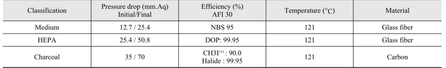
taken off line for cleaning or backwashing with compressed air, a so-called reverse flow. A compressor is equipped for the back pulsing of the bag house filter. The purpose of the chilled water equipment is to remove heat from the upper section of the bag filter for the protection of the filters in the filter bank. The off-gas is rapidly cooled to approximately 70°C using chilled water. The final filtration housing was designed to ensure that the amount of hazardous and radioactive particulates in the off-gas effluent is below all reference values, and to provide a means of determining, by monitoring the differential pressure, when the medium filter, HEPA filter, and charcoal filter should be changed. The specifications of the final filtration filters are summarized in Table 2. The off-gas enters a plenum in which it divides and enters one of two parallel paths in the filter housings. Another filter plenum is on standby for abnor-mal situations. Each gas stream passes through a medium fil-ter, a HEPA filfil-ter, and a carbon adsorber. Mercury and mer-cury-oxide control requires the injection of activated carbon into the gas stream, or the passing of the off-gas through car-bon beds [2]. A carcar-bon adsorber will have the added effect of removing organics in the gas stream, including dioxins and products of incomplete combustion (PICs). The total quantity and toxicity of PICs from incinerators is highly uncertain. The most widely-studied toxic PICs are known as dioxins.
The fans discharge vertically upward, both connecting to a common duct in which a sample is taken for emissions monitoring. The off-gas stream then merges with the building HAVC exhaust, and radiation monitoring is conducted before the combined flows discharge through the facility stack. The system uses a pair of 7.5 KW fans operating in parallel. The system is designed to be safely shut down using only one fan. For maintenance of negative pressure inside the incineration system, two blower fans are included. The main blower maintains negative pressure during normal operation. The negative pressure is held constant by means of the variable speed control of the drive motor. The pressure in the incinerator is controlled in the range of -15 mmH2O to -30 mmH2O.
The off-gas measuring and monitoring system (TMS) and radionuclide measuring system (i-CAM) are installed in a stack. A small amount of materials generated from the burning waste, however, will be released as undesirable air emissions. Regulations limit the allowable emissions that can be discharged from a stack into the atmosphere. When the emissions leaving an incinerator exceed the allowable stack emissions limit, control equipment for the air emissions must be provided to clean the exhaust gas before it is discharged into the atmosphere.
TMS was designed to measure the total suspended particulate
(TSP), CO, HCl, O2, NOx, and SOx contents after the gas
passes through the air pollution control system. An iso-kinetic TMS measures the stack velocity and uses a feedback control system to ensure that information on the gas drawn into the sampling and analysis system is displayed and archived in a dedicated personal-computer based data acquisition system. The iso-kinetic iCAM continuously draws a small quantity of air from the stack and passes it through a filter and a radiation monitor. The filters are periodically removed and sent to the measuring room for radiological analysis. The building is equipped with a HVAC system, which was designed to provide ventilation capacity for the incineration facility operation. The primary area of the ventilation is the incineration room, which is the major source of heat and radioactivity. The secondary area of the system’s auxiliary facility room, which has the possibility of being contaminated with radioactivity, generates a small amount of heat.
2.2 Operation Condition
The main materials in the incineration of radioactive waste consist of contaminated lumber, paper, cotton, cloth, gloves, vinyl, and PVC. A summary of this incineration material is given in Table 3.All instruments for indication of the status of each point of the process, such as pressure, temperature, and flow rate, were already turned on. The incinerator was heated to approximately 600°C using a preheating burner; feeding of the combustible waste package into the incinerator was started. The wastes were processed through the upper position of the incinerator using two sliding gates (Fig. 2). The combustible waste was packed using a paper bag. The weight of the single packages of lumber, cotton, vinyl, PVC, and mixed waste were around 1.5 kg.
Charcoal 35 / 70 Halide : 99.95CH3I131 : 90.0 121 Carbon
Table 3. Incineration material
Materials Amount of incineration (kg)
Ratio (%)
Lumber, paper 45.0 90
Cotton, Cloth, Gloves 3.5 7
Vinyl 0.25 0.5
PVC 1.25 2.5
After incinerating the radioactive waste, bottom and fly ash collected at different units was used to estimate the volume and weight reduction ratio.
3. RESULTS AND DISCUSSION
3.1 Volume ReductionAbout 220 drums of decommissioned combustible waste had been incinerated as of June 2013. The total weight reduc-tion ratio and volume reducreduc-tion radio were 1/10 and 1/50, respectively. According to the incineration criteria of low-and intermediate level-radioactive waste, the ignition loss of ash is less than 5%. The ignition loss values of UCF ash and KRR ash are 0.4% and 0.01%, respectively (Table 4.)
3.2 Off-Gas Analysis
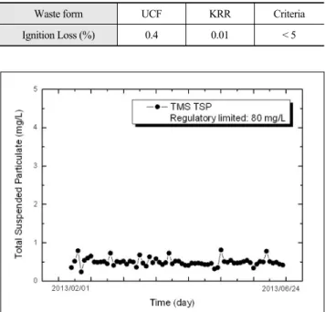
The burning process converts waste into gases and solids. The solids produced are either airborne, exiting the furnace in the flue gas (fly ash), or solid, ash that accumulates at the bottom of the unit. Gaseous discharge will exit the furnace in the flue gas. The majority of fur-nace emissions, on a per-volume basis, are gaseous. As with particulates, gaseous emissions can be classified as either combustible or non-combustible. Combustible gases include carbon monoxide, hydrocarbons, and other products of incomplete combustion. The presence of these gases is undesirable. When a furnace is operating properly, with sufficient air injection and a high enough temperature, almost all of the combustibles should be destroyed. The oxygen concentration of the stack TMS is approximately 20% during routine operation. The con-centration of the stack TMS TSP remained within the range of 0.3-0.5 mg/L (Fig. 3.). The concentration of TSP was sufficiently controlled to below the regulatory limit of 80 mg/L. TSP refers to all particles in the atmosphere. TSP includes only particles with an aerodynamic
diameter smaller than 10 µm. Ten microns is approx-imately one-seventh the diameter of a human hair. This fraction of TSP is responsible for most of the adverse human health effects of particulate matter because of the particles’ ability to reach the lower regions of the
respi-ratory tract. The major source of atmospheric particu-lates is fossil-fuel combustion, which produces ash and soot. Particles forming combustion and photochemical reactions are usually smaller in size (< 1 µm). Under very clean atmospheric conditions, the TSP level can be as low as 0.10 µg/m3. In a very dirty environment, TSP
concentration can be as high as 1,500 µg/m3[3].
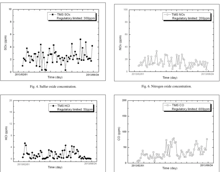
Larger particles, such as soot, fly ash, wood ash, and soil particles are composed primarily of minerals, including silicon, calcium, aluminum, iron, potassium, and other alkaline elements [4, 5]. The stack TELE monitoring values for SOx and HCl concentrations are shown in Fig. 4 and Fig. 5, respectively. Sulfur oxides and hydrogen chloride remained below the 5 ppm range for the majority of the facility operation. The regulatory limits of sulfur oxides and hydrogen chloride are 300 ppm and 50 ppm (corrected to 12% oxygen). Sulfur oxides and hydrogen chloride are noncombustible emissions that generate acidic compounds. They condense as they leave the stack and are reduced at temperatures below 149°C. Sulfur oxides form sulfuric acid, and hydrogen chloride condenses into hydrochloric acid, both of which contribute to atmospheric pollution and structural damage;
Fig. 2. Waste classification and feeding.
Table 4. Ignition loss of ash
Waste form UCF KRR Criteria Ignition Loss (%) 0.4 0.01 < 5
further, both have a potential health effects when emitted in sufficient quantities. Hydrogen chloride will form regardless of the conditions in the incinerator. In general, all of the chlorine in the chlorinate plastic components of the waste stream, as well as most of the other chlorine components in the wastes, will exit the incinerator as hydrogen chloride in the exhaust gas. The stack TELE monitoring values of the NOx concentration remained below 20 ppm, with occasional spikes to approximately 30 ppm (Fig. 6). The measured values are well within the emissions limit. The achievement of low NOx is a function of what happens to air as it passes through both the primary and secondary chambers. Since the kinetics of NOx formation is a function of both temperature and the stoichiometric ratio of the gas (i.e., NOx decomposes into sub-stoichiometric gases), systems that use the starved-air mode of operation in the primary combustor have a lower level of NOx than do excess-air systems. The stack TELE monitoring values of the CO concentration remained within a 10-50 ppm range for the majority of
normal operations (Fig. 7). Carbon monoxide is the most significant of all combustible gases. The allowable amount of carbon monoxide is normally limited to less than 600 ppm (corrected to 12% oxygen) by regulatory agencies, which in Korea is the Korea Institute of Nuclear Safety (KINS). The US EPA emissions limit is 150 ppm and the KINS limit is 600 ppm. Both the US EPA and the US government have proposed an MACT limit of 100 ppm [6]. Several CO spikes in excess of 50 ppm correspond to time periods of feeding of combustible material. The off-gas flow shows that the secondary airflow was not increased in anticipation of the feeding of the combustible waste. This will allow more oxygen into the afterburner during the processing of combustible materials. The measured gaseous materials in the stack are summarized in Table 5. The emissions concentration of all the gas materials measured are controlled to below the regulatory limits. These metals are converted into a gas phase (vaporized) when exposed to the high temperatures of the incinerator. When exhaust gases are cooled, these
Fig. 6. Nitrogen oxide concentration.
Fig. 7. Carbon monoxide concentration. Fig. 5. Hydrogen chloride concentration.
metals may either solidify or condense into other particulate matter in the off-gas. An important consideration in air emissions control system selection and design is to insure that flue gases are cooled to a low enough temperature when exiting the incinerator to allow the metals to condense into particulates. Using an emissions control system, unwanted particulate matter can be removed much more effectively from flue gas than can unwanted gases.
3.3 Dioxin
Dioxins (dibenzo-p-dioxins) are a family of chlorinated organic compounds. It has been found that the concentration of dioxins and furans is not related to the amount of chlorine present, but only to the presence itself of chlorine. Most fuels or other burnable materials contain some chlorine or chlorinated compounds, although often in very small amounts. Therefore, dioxins will be found just about any time burning occurs, whether this be the burning of charcoal, gasoline, cigarettes, or plastics. The measured data for PCDD and PSDF in the stack are summarized in Table 6. The concentrations of PSDD and PCDF were considerably below the regulatory limits. The favorable temperature range for the formation of polychlorinated dibenzodioxins (PCDD) and dibenzofurans (PCDF) is between 600°C and 300°C. To considerably reduce the formation of hazardous compounds, the off-gas temperature should be sustained below 300°C. The hot flue-gas (~850°C) leaving the afterburner chamber is cooled to 200°C in a double tube of air-cooled gas that is cooled outside with fresh air supplied by a blower, an air diluter, and a water chiller. This kind of cooling process
presents the advantage of maintaining the flue gas vol-ume at the minimum level and prevents the formation of PCDD and PCDF zones.
3.4 Radiation Emission
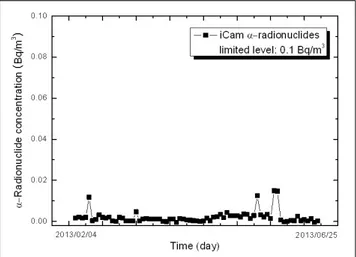
The emission concentration of and -Radionuclides, determined using iCAM in a stack, is shown in Fig. 8 and Fig. 9. The concentration of radionuclides was controlled to below the regulatory limit. One of the many technical challenges in incineration was described in a report on the behavior of Cs and Sr in high temperature processes. These isotopes are important because of their prevalence in wastes. The vaporization process depends on the temperature and on the chemical environment [7, 8]. Once vaporized, these species often nucleate or condense to form ultrafine particles (< 0.1 µm) that are difficult to collect at high efficiencies even when using an advanced particle control system [9, 10]. Therefore, the mechanism of particulate formation by volatilization and condensation is of special
Fig. 8. Alpha radionuclide concentration.
Fig. 9. Beta radionuclide concentration. Table 5. Gases material emissions concentration in stack
Gases material Regulatory limit Measured value Formaldehyde 10 ppm N. D Hydrogen cyanide 10 ppm N. D Bromine 5 ppm N. D Benzene 20 ppm N. D Phenol 10 ppm 0.29 Mercury 0.1 mg/Sm3 N. D Arsenic 5 ppm N. D Cadmium 0.2 mg/Sm3 N. D Chrome 0.5 mg/Sm3 0.076 Nickel 20 mg/Sm3 0.122 Zinc 10 mg/Sm3 0.376
Table 6. PSDD and PCDF concentrations
Regulatory limit 10 ng-TEQ/Sm3
4. CONCLUSIONS
Based on an analysis of the major critical parameters of the off-gas, it was found that the incineration facility operated quite smoothly. The negative pressure of the incineration chamber remained constant within the range specified. The off-gas flow and temperature were kept constant or were within the desired range. The measured gases and particulate materials in the stack were considerably below the regulatory limits. The volume reduction ratio achieved through incineration is about 1/50, and the weight reduction ratio is about 1/10. The facility was verified as one of the most effective technologies for volume reduction. Hazardous and decommissioned combustible wastes were treated safely during the incineration facility operation.
REFERENCES
[1] B.Y. Min, K.W. Lee, K.S. Yun and J.K. Moon, “Presents Status of the Decommissioning Combustible & Metallic Waste Treatment in KEARI,” JAPC-KAERI Scientific and Technical Exchange Meeting on Decommissioning, Korea (2012)
[2] C.R. Brunner and P.E. Dee, “Incinerator System Air Emissions Control”, POHengineer.com, Course No. EN-3007 (2012)
[3] A. Masitah, H. Zaini and S. K. Lee, “PM10 and total suspended particulates (TSP) measurements in various power station,” the Malaysian Journal of Analytical
Sciences, 11(1), pp. 255-261 (2007)
[4] Wisconsin. “Total suspended particulates,” Dept. of Natural Resource, retrieved at 16 March 2006 at http://www.dnr.state.wi.us/org/aw/air/health/tspart.html [5] J. Levy, K. J. Hammitt and D. J. Spengler, “Estimating
the mortality impact of particulate matter : What can be learned from Between-Study Variability,” Environmental Health Perspectives, 108 (2), (2000) [6] 40 CFR 266, Appendix IX: Methodology for the
Determination of Metals Emissions in Exhaust Gases from Hazardous Waste Incineration and Similar Combustion Source, (2004)
[7] T. Kady, M. Trichon and J. Feldmann, “Heavy metal in the stacks; Where are they?,” Proceedings of 1991
International Incineration Conference, Knoxville,
Tennessee, 597 (1991)
Conference, Pacific Northwest Laboratory, September (1994)
[10] H.C. Yang, J.H. Lee, J.G. Kim, J.H. Yoo and J.H. Kim, “Behavior of Radioactive Metal Surrogates Under Various Waste Combustion Conditions,” J. Korean