P1-38 / S. W. Hwang
• IMID 2009 DIGEST
Abstract
We investigate nematic liquid crystal (NLC) alignment on ion-beam exposed ZnO films. ZnO is optically transparent material in the visible range. We optimized the deposition parameters such as deposition temperature and gas ratio for high transmittance and resistivity. Using ion-beam treated ZnO films, LC cells are fabricated and the conditions such as exposure energy and time for uniform alignment are found. The NLC molecules align parallel to the ion-beam exposure direction. The electro-optic and response characteristics show the possibility of application of this method in liquid crystal display.
1. Introduction
In general, it has been reported that inorganic alignment layer has lower transmittance than organic one [1]. The high transmittance of the alignment layer is important because transmittance is related to the energy efficiency in liquid crystal displays (LCDs). Therefore, we need to find new highly transparent inorganic materials. The candidate of highly transparent inorganic material is ZnO. ZnO has been known as a good applicant in optical devices such as transparent electrode and solar cell because of high optical transparency in the visible range [2, 3]. Also, ZnO has high deposition rate and can be deposited on any substrate.
In this study, we aligned liquid crystal (LC) molecules on ion-beam exposed ZnO films. ZnO films are deposited by a radio frequency (RF)-magnetron sputter. We optimized deposition parameters such as argon and oxygen gas ratio and deposition temperature for high transmittance and resistivity. Using ion-beam treated ZnO films, LC cells are fabricated and the alignment states are checked. The exposure parameters such as exposure energy and time are varied and the conditions for uniform alignment are found.
2. Experimental
ZnO films are deposited on indium tin oxide coated glass substrate by a RF-magnetron sputter. The initial and working pressures of the vacuum chamber are below 5×10⁻⁶ and 1×10⁻² torr, respectively. The
RF-power and distance between target and substrate were 70 W and 10 cm, respectively. We optimized deposition parameters such as argon and oxygen gas ratio and deposition temperature for high transmittance and resistivity. The argon gas flow is fixed at 50 sccm. The oxygen gas flow is varied from 0 to 50 sccm. The deposition temperature is varied from 25 to 400 ℃. The resistivity and transmittance of ZnO films are measured using 2-point probe and optical spectroscopy (Photal Otsuka Electronics, MCPD-3000). We measured the film thickness and calculated deposition rate of the ZnO films.
We exposed ion-beam on the deposited ZnO films for uniform homogeneous alignment of the LC molecules. The ion-beam source is a cold hollow cathode type with Ar+ ions as the ion source. The base and working
pressures were 5×10⁻⁶ and 1×10⁻⁴ torr, respectively. Argon gas flow was 5.6 sccm. When the ion-beam is exposed on the ZnO film surface, the distance between the ion-beam source and alignment layer and the incident angle are fixed at 15 cm and 15 °, respectively. LC cells are fabricated and the alignment states are checked using back light unit and crossed polarizers. The LC cells are fabricated with a cell gap of 3.8 µm. The LC used here is ML-0223 (∆n = 0.0809, ∆ε = 3.9, Merck). The exposure energy and time are varied and the conditions for uniform alignment are found. The exposure energy and time are varied from 50 to 500 eV and 0 to 300 seconds, respectively.
The electro-optical characteristics and response times are measured for the possibility of application in LCDs, and these have been compared with conventional rubbing cells on polyimide.
Alignment of Liquid Crystal on Ion-Beam Exposed ZnO Film
Soo Won Hwang, Tae-Hoon Yoon and Jae Chang Kim
School of Electrical Engineering, Pusan National University, Busan, 609-735, Korea Tel.:82-51-510-1700, E-mail: [email protected]
P1-38 / S. W. Hwang
IMID 2009 DIGEST •
3. Results and discussion
1. Deposition of ZnO film
Figure 1 shows the transmittance of ZnO film for various argon and oxygen gas ratios. Deposition temperature is fixed at 200 ℃. The transmittance of ZnO film also increased with the increase of oxygen pressure. This is because the density of the defect decreases as the oxygen vacancies decrease with oxygen supply. This result coincides with the resistivity of ZnO films for various argon and oxygen gas ratio. When oxygen flow is zero, the resistivity of ZnO film is 105 Ω·cm. With an oxygen supply, the
resistivity of ZnO film is over 1010 Ω·cm.
Fig. 1. Transmittance vs. wavelength for various argon and oxygen ratios.
Figure 2 shows the transmittance of ZnO film for various deposition temperatures. The transmittance of ZnO film was also enhanced with the increase in deposition temperature.
Fig. 2. Transmittance vs. wavelength for various deposition temperature.
We measured the thickness for various deposition time. Figure 3 shows the thickness vs. deposition time. We
calculated the deposition rate using Fig. 3. Where the deposition temperature, the argon and oxygen flow rates are 200 ℃, 50 and 25 sccm, respectively. The calculated deposition rate was 30 Å/min.
Fig. 3. The thickness of ZnO film for various deposition time.
2. Fabrication of the cell using ion-beam treated ZnO film
We fabricated several homogeneous LC cells using ion-beam treated ZnO films. The exposure energy and time is varied. Figure 4 shows the conditions for uniform alignment. For uniform alignment, the exposure energy and time are needed over 250 eV and 60 seconds, simultaneously. Without sufficient exposure energy and time, LC molecules could not be aligned.
Fig. 4. Conditions of homogeneous alignment for various exposure energy and time.
Figure 5 shows the LC cells sandwiched between a pair of crossed polarizers without electric field. The cell is fabricated using ion-beam treated ZnO film at 250 eV and 120 seconds. We can observe a dark and bright state when the ion-beam exposure direction of the LC cell is oriented at 0 and 45˚ relative to the transmission axes of the polarizers. This indicates that
P1-38 / S. W. Hwang
• IMID 2009 DIGEST
the optic axis of LC cell is parallel to the exposure direction and the LC molecule is aligned parallel to the ion beam direction.
Fig. 5. The photograph of an LC cell where the ion-beam exposure direction is oriented at (a) 0, and (b) 45˚ relative to the transmission axes of the polarizers.
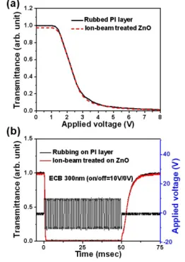
We measured the electro-optical characteristics and compared with a conventional rubbed cell on polyimide. Figure 6 shows the electro-optic and response characteristics of a rubbing cell on polyimide and an ion-beam exposed ZnO cell. The threshold voltage and response time are almost identical. The threshold voltage, turn on time and turn off time are 1.2 V, 0.58 and 8.45msec, respectively. This results show the possibility of application of this method in LCDs.
Fig. 6. (a) The electro-optic and (b) response characteristics of a conventional rubbed polyimide cell and an ion-beam exposed ZnO cell.
4. Summary
Several uniformly aligned LC cells were fabricated on ZnO inorganic films using the ion-beam exposure method. The ZnO thin films show a high transmittance of over 90 % and a high deposition rate. The LC molecules align parallel to the ion-beam exposure direction for sufficient ion-beam exposure energy and time. The electro-optic and response characteristics of ion-beam treated ZnO cell show the possibility of application of this method in LCDs.
Acknowledgement
This work was supported by the Second Phase BK21 Program of the Ministry of Education & Human Resources Development, Korea.
5. References
1. P. K. Son, J. H. Park, J. C. Kim and T. -H. Yoon: Thin Solid Films, 515, 3102, 2007.
2. B. Sang, A. Yamada, M. Konagai, Jpn. J. Appl. Phys. 37 L206, 1998.
3. J. G. Lu, Z. Z. Ye, Y. J. Zeng, L. P. Zhu, L. Wang, J. Yuan, Q. L. Liang and B. H. Zhao: J. Appl. Phys 100, 2006.
4. P. K. Son, J. H. Park, J. C. Kim, T. -H. Yoon, S. J. Rho, B. K. Jeon, S. T. Shin. J. S. Kim, S. K. Lim: Appl. Phys. Lett. 91 103513, 2007.