ICCAS2005 June 2-5, KINTEX, Gyeonggi-Do, Korea
1. INTRODUCTION
Robot can be used in industry, extremely dangerous environment, medicine, entertainment and humanoid close to human. In addition, robot can be adjusted with several forms in various fields. Hardware and control software of robot tend to be more complicated and used with diverse sensors and actuators. For that reason, many developers participate in robot development, and multifarious programs are used in various platforms. As middleware is needed in distributed environment including these multiplications, this study explains the robot software component interface abstraction to add transparency and flexibility of robot software.
Before this study, CMR (Component based Modularized Robot) and FMR (Function based Modularized Robot) were developed [1-4]. The purpose of this study is researching architecture of hardware and software platform with modularized and standardized methods based on robot that can be applicable in various fields. This study proposes the middleware that is used in distributed environment and diverse components such as Vision, Navigation, Localization, Motor Driver and Motion Driver, which consist of robot software. Disadvantage of established robot is a lack of transparency and flexibility of control software. For instance, it is difficult to change existing sensor or add new sensor for progressing function of robot. And software which was developed in existing robot has a trouble in porting to new robot. This structure of robot software needs much time to porting, and it is ineffective to develop hardware and software on both sides.
This study tries to solve the problem that was said above by separating software from robot hardware and using hierarchical structure of software [5,6]. This study suggests a scheme, which makes standard abstract interface of robot software component to be composed hierarchically, for compatibility of robot and reuse of control software. This method is similar with abstraction of device in operation system.
There are several advantages when software component is distributed in various platforms connected to distributed network more than in a single platform. For example, a robot has to attaches all requested sensors and actuators, but the
voluminous and heavy sensor can be separately installed from the robot. In another example, if expensive sensors have to be installed in several robots, it can design that several robots can use one sensor. A desktop in which control software is installed can control several robots that have just an actuator. At this time, one localization sensor attached on the ceiling can trace the position of several robots [7].
There are CORBA and DCOM used in distributed environment [8,9]. However, because CORBA and DCOM are developed for general purpose, these need excessive resource for using robot and have no guarantee to ensure predictive operation, which should need real time. Moreover, communication media like CAN or RS-232 can not be used, and it is hard to develop subordinate protocol about the new communication media. For this study, we use MRSF(Modularized Robot Software Framework) architecture that was developed in System engineering project for personal robot. The MRSF architecture running on distributed environment allows robot control programs to be written in any programming language and to run on any computer with a network connection to a robot [10,11].
2. HAL
Hardware Abstraction Layer(HAL) is a general concept used in software like operating system and virtual machine. HAL allows operating system to have compatibility with many processors by separating operating system from platform dependent part and processor. In Linux, there are already lots of useful devices and developed applications. Application developers can exploit irrelevantly application programs in subordinate platforms.
Diverse constructed robots have practical differences in hardware. For example, there is a robot that uses a vision or tactual sense to recognize environments, and a robot that uses wheels or legs to move. This study offers HAL between control-monitoring software and hardware, and standardizes the interface. HAL provides equal abstractions to subordinate sensor and actuator components, and the control-monitoring software operates transparently about the subordinate robot hardware. It gives the robot control software to be
Robot software component interface abstractions for distributed
sensor and actuator
KwangWoong Yang
*, DaeHeui Won
*, Moosung Choi
*, Hongseok Kim
*Taegeun Lee
*,SangJoo Kwon
**, and Joon Woo Park
**** Division of Applied Robot Technology , KITECH, Ansan, Korea
(Tel : +82-31-400-3989; E-mail: {ygkgwg, daehee, moosung, hskim}@kitech.re.kr, [email protected]) ** School of Aerospace & Mechanical Engineering, HAU, Seoul, Korea
(Tel : +82-2-300-0178; E-mail: [email protected])** *** Fine Digital Inc., Korea
(Tel : +82-31-788-8852; E-mail: [email protected])
Abstract: Robot is composed of various devices but, those are incompatible with each other and hardly developing reusable
control software. This study suggests standard abstract interface for robot software component to make portable device and reusable control software of robot, based on familiar techniques to abstract device in operating systems. This assures uniform abstracted interface to the device driver software like sensor and actuator and, control program can be transparent operation over device. This study can separately and independently develop devices and control software with this idea. This makes it possible to replace existing devices with new devices which have an improved performance.
independently made. Hence, the control software developed for one robot can be ported into other robots.
The MRSF has to have transparent and portable structures, although the particular way in which MRSF is implemented is not fitting for all robotic application domains. This study adds HAL specification to the MRSF architecture for separating the robot software from the robot hardware and using hierarchical structures of software. HAL specification defines interfaces of the software component for connection between software and hardware, and defines a profile to describe characteristics of hardware.
Interface is the specification expressed for abstracted functions of a device. Property and method are used to describe the interface specification. For instance, a number of sensors in sensor array can be described in the property, and a command reading a sensor can be described in the method. And the interface is a agreement to provide transparent access between software components in distributed network. As this agreement defines, interface definition language is need independency on particular languages like C, C++ and Java. MRSF architecture use MIDL (Module Interface Definition Language) that is similar with IDL of CORBA and DCOM and suitable to robot modules. The interface described with MIDL composes of attributes and methods, and can use inheritance. The interface described with MIDL is translated into stub and skeleton code proper to programming languages through MIDL compiler. MIDL is not a programming language but an interface definition language, which embodies the software component programmed through C or C++. MIDL supports a mapping of C, C++, RPL (Robot Programming Language), Java, Python and Visual Basic.
Sensor and actuator devices are grouped together by its functions. Therefore, the device which performs similar functions deals in the same device in point of a user and sorts out the same class. Although device drivers and the software component in the same class have the same interface, they can have different internal structures. The driver, as a software code for the interface, adequately controls the device for carrying out requested functions. In general, the device driver is made subordinate to the specific hardware. Though the software, which directly controls and monitors hardware, is classified into the device driver, it belongs to the software component.
Although the device driver is belonged in the same class, there are different characteristics. They are described in a profile of a device. Various features of the device are written in the profile. For example, a diameter of a wheel, length of an axle, size and weight of a robot make a description of the profile.
3. ABSTRACT TO A STANDARD INTERFACE
Function of a robot is classified into working, moving, sensing, and processing. For moving, the robot has to recognize environment, avoid an obstacle, and localize a position. And a manipulator needs for working. Wheels need or more than two legs like an animal need for moving. There are four types of sensors recognizing environments. One is the sensor that perceives absolute position, relative distance between objects, and movable quantity. The other is the camera that perceives an object, color, and motion as an animal sight. This study sorts multifarious devices in a complex robot system and extract appropriate interfaces.
There is an ambiguous case to separate a boundary of the abstracted device. For instance, there is a sonar satellite receiver that can directly read a position of a robot and a laser finder using distance measurement that can use position
measurement with Markov localization. Though it is important to know the position of the robot, it can also know the distance from obstacles to avoid. Therefore, the abstract layer about sensor devices is consisted of multiple layers for the position and distance measurements.
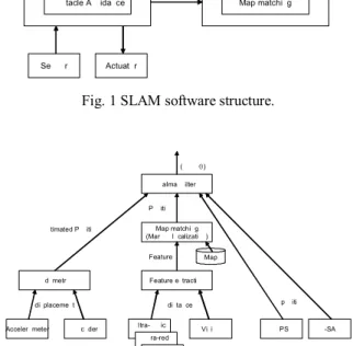
Even though it is easy to design an interface in one kind of a device, it is not simple to generalize an interface including various kinds of devices. The interface provided in this study cannot ensure that support all devices. To extract interface, at first, all devices and robot software components that used in CMR and FMR display in block diagram. The device driver or the software component performs functions displays in rectangle, and the data flow between them displays in arrow. The figure 1 indicates the SLAM software structure using to a robot. The figure 2 indicates the detailed structure of localization component inside SLAM software. The figure 3 displays the detailed structure of obstacle avoidance component inside SLAM software. There is no the detailed structure of path planning and map building software.
Map Building Navigation Maintenance Map Map matching Localization Obstacle Avoidance Path Planning Actuator Sensor
Fig. 1 SLAM software structure.
Kalman filter Map matching (Markov localization) Feature extraction Vision Ultra-sonic Infra-red Laser Finder Encoder Accelerometer Odometry GPS U-SAT Map
displacement distance position
Feature Position Estimated Position
(x, y , θ)
Fig. 2 Localization software structure.
VFH (Vector Field Histogram), Wall following Obstacle Map Ultra-sonic Infra-red Laser Finder Distance (driving velocity, angular velocity) Encoder PID, DOB, Optimal control Target (x, y , θ) Motor Current (x, y , θ) Forward Kinematics Left/Right wheel velocity
Sensors and actuators using in a robot are classified into device classes by its measurement data type, and the block inputted similar data and commands in the data flow between robot software blocks is classified into the component belonged the same class.
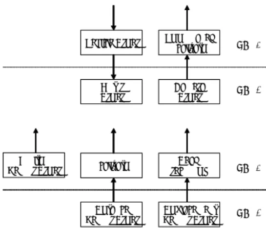
Standard abstract interface is defined in generalized functions of similar devices in same class. A profile obtains each different characteristic of the similar devices. The software component of two layered structures about sensors and actuators is displayed in figure 4.
Displacement Sensor Driver Distance Sensor Driver Position Sensor Driver Dead reckoning Localization Camera Driver Motor Driver Vision based Localization Vehicle Driver HAL 0 HAL 1 HAL 0 HAL 1
Fig. 4 Layered software component structure. Because commercial devices are made for using general purposes, they contain most functions. However, wrapping code has to be made for converting into standard interface, because it is not corresponding with the structure proposed in this study.
3.1 Vehicle
The mobile module of synchronized method in HANWOOL Inc. and own making mobile module of differential method are used for interface abstractions of the vehicle device. Because the differential module is simply composed, it is usually made by oneself with a motor, reducer, and encoder. Faulhaber MCDC2805, a motion controller, or own making motion controller is used to control a motor. The motion controller interface is abstracted to allow control software of the mobile module to approach transparently to the motion controller. The mobile makes up two layered interfaces: Motor Device that directly controls and monitors position and speed and Vehicle Device that controls position and speed.
(1) Motor Driver
A motor and encoder can use closed loop controls such as PID or Optimal control. Most commercial motor controllers use position control and speed control, and an encoder value and speed can be read.
Motor device interface has the Initiate(), DefineHomePosition(), VelocityCtl(), RelativePositionCtl(), and AbsolutePositionCtl() of the method and has the Position, Velocity, and Acceleration of the property.
There are the Operation Mode, Encoder Resolution, Position Limits, Minimum Velocity, Maximum Velocity, and Acceleration in a profile of motor.
(2) Vehicle Driver
In the three-dimensional space, a position of a rigid body is expressive into six values of latitude, longitude, altitude, roll,
pitch, and yaw. The position of a mobile robot indicates with three degrees of freedom (x, y, θ) in a plane. The vehicle with synchronized driver with turret and omni-directional movement driver can indicate four degrees of freedom (x, y,
θ1, θ2) because of a difference of moving direction and
heading.
Most robot software use velocity control more than position control for driving a vehicle. The vehicle driver is possible to use relative position control, absolute position control, and the velocity control. It can also estimate position with encoder values. Vehicle device interface has the Initiate(), GoForward(), GotoRelativeXY(), GotoAbsoluteXY(), Stop(), TorqueFree(), Drive(), SetOdometry(), SetVelocity(), and SetAcceleration() of the method and has the Running, Odometry, Velocity, and Encoder of the property.
There are the Maximum Velocity, Acceleration, StdDeviation, Offset, WheelDiameter, AxleLength, Maneuverability, and DegreeOfFreedom in a profile.
3.2 Sensor
A sensor is classified into absolute position sensor, relative distance senor, and displacement sensor. The relative distance sensor measures the distance between a sensor and an object, however the absolute position sensor measures a position of a robot (x, y) or (x, y, θ) from a reference. Displacement sensor perceives a displaceable quantity of position (Δx, Δy) or a displaceable quantity of direction (Δθ) in a robot.
The interface of all sensor classes has the Initiate() and ReadData() of the method and has the MeasurementCount, MeasurementData of the property. There are the LimitsMin, LimitsMax, Deviation, SpreadRadius, NumberOfMeasruement, Offset, Adjustment Polynominal, MaximumVariance, MaximumVarianceCount, and Averagingcount in a profile.
(1) Position Sensor Driver
GPS(Global Positioning System), PSD(Position Sensitive Detector), RFID(Radio Frequency Identifier), U-SAT(Ultra-sonar Satellite System), and Landmark based Vision are used for recognizing position of a robot. GPS, PSD, RFID, and U-SAT can recognize the position (x, y), but it cannot recognize the direction. To predict the direction, the robot has to move. The direction is estimated from displaceable quantity of the odometry and displaceable quantity of the position measured the sensor.
Using the PSD device can detect the position about several robots. The PSD sensor on the ceiling detects an infrared light radiated from the robot, and PSD device allows the robot to know the position.
(2) Distance Sensor Driver
For measuring the relative distance between a robot and an object, sonar sensor array, infrared sensor array, and laser finder are used. The robot needs to know both of the relative distance and the absolute position to move. The relative distance sensor is utilized for avoiding obstacle, and the absolute position sensor is utilized for seizing position. However, the absolute position can be probabilistically computed from the relative distance sensor by Markov localization. Markov localization component belongs to the same class with the position sensor driver.
(3) Displacement Sensor Driver
The sensor, which measures a movable quantity such as acceleration sensor and encoder, integrates the movable quantity to estimate a position of a robot. Therefore, an error is continuously accumulated, if the moving distance increases. The absolute position sensor is needed to compensate the error. Kalman filter can compensate the movable quantity and the absolute position.
(4) Camera Driver
A camera can input enormous data at low cost. However, it needs high efficiency processors to extract requested information. Images inputted from the camera are used in various fields such as localization, distance measurement, object recognition, color recognition, and motion detection. The 320x240-sized image and 640x480-sized image, which is formatted in RGB24, can be inputted.
4. IMPLEMENTATION
This study made scenario to show how the interface abstraction works efficiently in the robot software component about distributed sensors and actuators. First, a control software is developed on a remote PC by simulating sensors and actuators of a robot on a local PC. A simulation can develop the compatible software because it can test diverse cases that cannot be tested in real hardware. Second, if the control software development is somewhat completed, the simulator is changed into the robot hardware device and device drivers. It can be easily done by linked information is modified. The control software connected to the robot hardware has the problem that is not predicted in the simulator. There are an advantage of the software development and debugging by using a laptop or a desktop as a remote PC. Third, if a hardware test is completed, a robot can independently carry out functions by loading the control software developed on a remote PC to a robot. The last, when sensors and actuators in a robot are changed in different kind of the same class, these are checked working correctly in control software.
The simulator which is now using can simulate sensor devices and vehicle devices except for RFID sensors and camera devices. The simulator exists in each device class and can make various sensors that have different features if it changes a profile in the simulator.
The differential driver and the synchronized driver of HANWOOL Inc. are used to check for interface abstractions of the vehicle device driver. The synchronized driver has four degrees of freedom (x, y, θ1, θ2) but control software does
not support four degrees of freedom, so the synchronized driver is modified to corresponded robot heading and turret direction.
The robot frame is designed for which it can be portable as possible as many sensors. During the test, the sensor is tested individually. The RFID sensor knows the position but not the heading. Markov localization is used for accurately perceiving the robot position, and the heading is predicted through Kalman filter. U-SAT sensor uses four sonar satellites as a position measurement system. If one of them is disappeared by robot entering particular part, the wrong position is outputted because of reflected waves. It has a trouble in complex places with partitions and tables.
The skeleton code is made by MIDL compiler using the interface of the device driver defines with the MIDL. C and C++ are used to make the device driver.
The stub code which is used in robot software is made by MIDL compiler using the interface of the device driver. The robot software can be made with C, C++, Java, Python and Visual Basic.
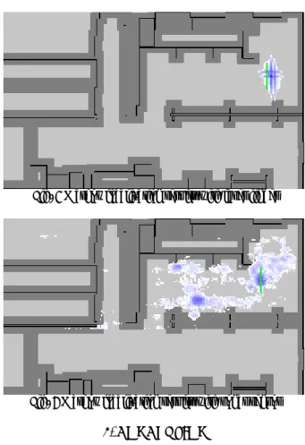
The figure 5 and 6 are tested results by interchanging a laser finder and a sonar sensor array in the same Markov Localization software. Green cross indicates the position of a robot. The probability that the robot will be positioned is higher in deep blue part. Though two sensors execute the Localization by transferring the robot into the similar position, each result of the sensor shows different outputs. An error
between the position of the robot and the highest point of probability in figure 6 is that the laser finder has an offset from a center of the robot.
Fig. 5 Markov localization results with laser finder
Fig. 6 Markov localization results with sonar sensor
5. CONCLUSION
The purpose of this study is the research of Hardware Abstraction Layer (HAL) that makes the robot software develop independent on hardware. For this study, HAL is added in the MRSF architecture. HAL allows the robot software developed for one robot to efficiently transplant into other robots. Moreover, HAL can change existing sensors and actuators of a robot without amending the robot software.
Although designed and embodied interfaces that can be used in general purpose with various sensors and actuators on a robot, it can not be adjusted in all robots. One interface which is completed and standard will not be found. However, there is a need to make the abstracted interface for general and useful purposes. In the future, device drivers about more sensors and actuators should be developed, and Abstract Device Interface about a manipulator has to make a progress.
ACKNOWLEDGMENTS
This study is partially supported by Personal Robot Development Project under grant of Next Generation Technology Development Project.
REFERENCES
[1] Sin-Wook Ryu, KwangWoog Yang, Hong-Seok Kim, Ho-Gil Lee, “Functionally Distributed Modular Robot System using Virtual Machine,” Proceedings of ICCAS, pp.2330-2335, Muju, Korea, Oct. 16-19, 2002.
[2] S. G. Roh, S. M. Baek, D. H. Lee, K. H. Park, T. K. Moon, S.W. Ryew, J. Y. Kim, T. Y. Kuc, H. S. Kim, H. G.
Lee, H. R. Choi, "Development of Personal Robot Platform : Approach for Modular Desing," ICCAS, pp. 2313-2318, October 2002.
[3] S. G. Roh, K. H. Park, K. W. Yang, H. S. Kim, H. G. Lee, and H. R. Choi, "Development of Dynamically Reconfigurable Personal Robot," ICRA, pp.4023-4028, 2004.
[4] S.G. Roh, K.H. Park, K.W. Yang, J.H. Park, H.S. Kim, H.G. Lee and H.R. Choi, "Dynamic Infrastructure for Personal Robot : DynI," ICCAS, pp. 2039 - 2044, 2003. [5] Richard T. Vaughan, Brian P. Gerkey and Andrew
Howard, “On device abstractions for portable, reusable robot code,” Proceedings of IROS 2003, Las Vegas, Nevada, October, 2003.
[6] Brian P. Gerkey, Richard T. /Vaughan and Andrew Howard, “The Player/Stage Project: Tools for Multi-Robot and Distributed Sensor Systems,”
Proceedings of ICAR 2003, pp.317-323, June 30 – July 3,
2003, Coimbra, Portugal, 2003.
[7] Brian P. Gerkey, Richard T. Vaughan, Kasper Stoy, Andrew Howard, Gaurav S. ?sukhatme and Maja J Mataric, “Most Valuable Player: A Robot Device Server for distributed Control,” Proceedings of IROS 2001, pp. 1226-1231, Vailea, Hawaii, 29 Oct. - 3 Nov., 2001. [8] "Common Object Request Broker Architecture: Core
Specification," OMG, Mar. 2004.
[9] Markus Horstmann and Mary Kirtland, "DCOM Architecture," MSDN, Jul. 1997.
[10] Gun Yoon, Hyoung Yuk Kim, Ju Sung Lee, Hong Seok Kim, Hong Seong Park, “Middleware Structure for Personal Robot,”ICCAS, pp. 153-157, Jun. 2003. [11] KwangWoong Yang, Hong-Seok Kim, Jaehyun Park, “A
Virtual Machine for Modularized Personal Robot Controller,” Proceedings of ICCAS, pp.2170-2173, Muju, Korea, Oct. 16-19, 2002.