Radiative Heat Transfer Modeling for the Thermal Analysis of a High Temperature
Gas-Cooled Reactor
Jongtae Kim, Sang-Baik Kim, Won-Jae Lee
Div. of Thermo-Hydraulics and Safety Research, KAERI, Daejeon Korea, [email protected]
1. Introduction
Radiative heat transfer (RHT) can be a major mode of heat transfer in a high temperature gas-cooled reactor (GCR) especially under accident conditions.
For several decades, many methods have been developed for solving the RHT. These are grouped into two parts depending on the participation of a medium. The view-factor and ray-tracing models are mainly used for a surface-to-surface radiation. P-N, DOM, and finite volume (FV) methods are usually used for absorbing and emitting media. The surface-to-surface radiation models have been used for a GCR because the helium and air used as a coolant in the reactor core or reactor cavity cooling system are non-participating media. But these methods have a limitation in applying to general CFD meshes because of the resulting large matrix size.
In this study, FV radiative transfer equation (RTE) model is adopted and a RHT module for the LILAC [1] CFD code has been developed because it is independent on the optical thickness of the medium. And it is validated by solving some benchmark problems.
2. Numerical model
The RTE for a gray absorbing, emitting and
scattering medium in a direction sˆ may be written as [2]
)
ˆ
(
)
ˆ
,
(
)
(
)
ˆ
,
(
r
s
k
I
r
s
B
s
I
s
)
⋅
∇
r
=
−
+
σ
sr
+
(1)where B is the intensity gain from emission and in-scattering in all directions.
∫
Φ
′
Ω′
+
=
ππ
σ
4)
ˆ
,
ˆ
(
)
ˆ
,
(
4
)
ˆ
(
s
kI
I
r
s
s
s
d
B
s Br
(2)Here k is the absorption coefficient, σsis the scattering
coefficient, I is the black-body intensity and Φ is the B scattering phase function. On gray-diffuse surfaces, the boundary intensity is given by eq. (3).
∫
⋅+
Ω
⋅
−
=
n s b b b bT
d
n
s
s
r
I
I
ˆ ˆ 4ˆ
ˆ
)
ˆ
,
(
)
1
(
π
σ
ε
π
ε
r
(3) The energy added to the medium by the radiation, which acts as a source in the energy equation, is given as:∫
−
Ω
=
π 4]
)
ˆ
,
(
[
I
r
s
I
d
k
S
rr
B (4)Following the standard finite volume procedure, eq. (1) is integrated over finite volume and finite angle [3].
∫ ∫
∫ ∫
∫ ∫
∆Ω ∆ ∆Ω ∆ ∆Ω ∆Ω
+
Ω
+
−
=
Ω
∇
⋅
V V s VdVd
B
dVd
I
k
dVd
I
s
)
(
ˆ
σ
(5)Applying the divergence theorem, left-hand side of eq. (5) results in surface integral, and is finally discretized by using the 1-point quadrature as shown in eq. (6).
∑
∑
⋅
∫
Ω
=
⋅
∆Ω f i f if f i f ifA
s
d
I
A
S
I
iv
r
r
ˆ
(6)The right-hand side of eq. (5), which represents the attenuation and augmentation of the radiative intensity, is simplified as shown in eq. (7).
∑
=
−
+
+
∆Ω
∆
f i i i s if ifJ
k
I
B
V
I
[
(
σ
)
0]
0 (7)Eq. (7) is the finite volume representation of the RTE which describes the conservation of the radiative energy in each control volume and control angle. Here, I is if the intensity associated with the direction i at the face f of the control volume, and I is the intensity at the cell i0 C0 in the direction i. By using the standard step approximation [4], the face intensity is defined as the value of the upwind cell.
upwind i
if
I
I
=
, (8)In order to solve the eq. (7), it is necessary to discretize the spatial domain and the angular space. The spatial domain is discretized with arbitrary shaped cells, and the angular space 4π is discretized into non-overlapping control angles. The discretized RTE of eq. (7) is solved using a conjugate-gradient iterative matrix solver for each discrete control angle.
3. Numerical Results
Based on the numerical method describe above, a radiative heat transfer module of the LILAC CFD code has been developed. To investigate the accuracy and computing efficiency of the module, three benchmark problems have been chosen and solved.
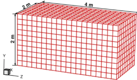
X Y Z 2 m 2 m 4 m
Fig. 1 3-D mesh for the idealized furnace
The first benchmark problem is 3-D idealized furnace proposed by Menguc et al. [5]. Fig. 1 depicts the computational domain and the generated surface mesh. The furnace is filled with a gray gas with k=0.5 and σ=0. The RTE is coupled with the energy equation with a Transactions of the Korean Nuclear Society Autumn Meeting
heat source of 5kW/m3. The wall temperatures at z=0 and z=4 are 1200K and 400K. And all the other walls have temperature 400K. Fig. 2 shows the temperature distributions at y=1m, The results are in good agreement with the zone solution of Menguc and Viskanta.
x [m ] T e m p e ra tu re [K ] 0 0 . 5 1 1 . 5 2 8 0 0 9 0 0 1 0 0 0 1 1 0 0 1 2 0 0 P r e s e n t M e n g u c a n d V is k a n t a ( 1 9 8 5 ) z = 0 . 4 z = 2 . 0 z = 3 . 6
Fig. 2 Comparison of temperature distributions at y=1.0 location for the idealized furnace
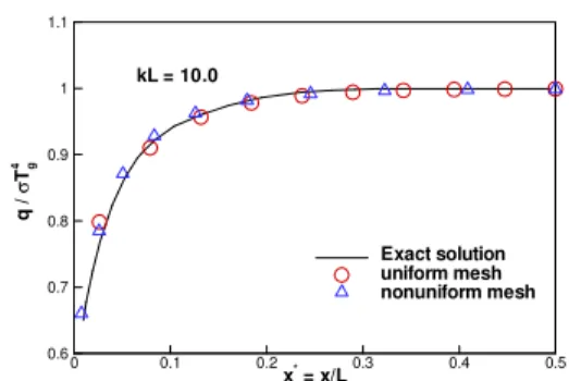
The second problem chosen for the validation of the numerical model is the prediction of surface heat transfer in a square enclosure with cold walls (at 0 K), which contains a non-scattering emitting gas at uniform
temperature Tg. The exact radiative heat flux on the wall
of the square cavity is described in the ref [3] and used for a comparison with present results. In this study, uniform and non-uniformly generated grids are used to check the grid dependency, as shown in Fig. 3. The calculated local heat flux on the bottom wall is plotted in Fig. 4 and 5 for the cases of weakly emitting (kL=0.1) and strongly emitting (kL=10) media. The figures depicts that the current model predicts well the radiative heat transfer.
(a) (b)
Fig. 3 2-D black enclosure with emitting medium, (a) uniform mesh, (b) non-uniform mesh
x* = x/L q / σ Tg 4 0 0.1 0.2 0.3 0.4 0.5 0.06 0.07 0.08 0.09 0.1 0.11 kL = 0.1 Exact solution Uniform mesh Nonuniform mesh
Fig. 4 Heat flux distributions on the bottom wall of the black enclosure for an optically thin case (kL=0.1)
x* = x/L q / σ Tg 4 0 0.1 0.2 0.3 0.4 0.5 0.6 0.7 0.8 0.9 1 1.1 kL = 10.0 Exact solution uniform mesh nonuniform mesh
Fig. 5 Heat flux distributions on the bottom wall of the black enclosure for an optically thick case (kL=10.0)
The third benchmark problem is a surface-to-surface radiation case. The medium enclosed by a equilateral triangle does not participate in the radiative heat transfer. As shown in Fig. 6, the bottom wall temperature is higher than the other two side walls. The exact heat flux on the each wall was calculated by using the view-factor method. In this case, RTE is solved with the medium emissivity equal to 0, which means that the radiative intensity emitted from each wall is not attenuated. The calculated wall heat fluxes seem to be comparatively good (see Table 1).
S u rfa ce 2, L 2= 1m , T 2= 40 0K Surface 1, L1= 1m, T1= 600K Su rfa ce 3, L 3 =1 m, T3 =4 00K
Fig. 6 Mesh for a equilateral triangular enclosure Table 1 Radiative heat fluxes on the surfaces of the triangular
enclosure
4. Conclusion
The thermal radiation module of the LILAC code has been developed and validated in this study. It was found that the RTE model can be applied to optically thick and transparent non-emitting media. In the future study, the developed code will be used to study heat transfer in the gas-cooled reactor.
REFERENCES
[1] J. Kim, et al., KAERI/TR-2126/2002, 2002
[2] R. Siegel, et al., Thermal Radiation Heat Transfer, 2001 [3] G.D. Raithby, et al., J. of Heat Transfer, Vol.112,
pp.415-423, 1990
[4] J.C. Chai, et al., J. of Thermophysics and Heat Transfer, Vol.8, No.3, pp.419-425, 1994
[5] Menguc, et al., JQSTR vol.31, No.6, pp.533-549, 1985
s u r f a c e 1 s u r f a c e 2 s u r f a c e 3 E x a c t [ W ] 5 8 9 5 . 8 - 2 9 4 7 . 9 - 2 9 4 7 . 9 C a lc u la t e d [ W ] 5 8 9 1 . 3 - 2 9 0 4 . 6 - 2 9 0 8 . 2 E r r o r [ % ] 0 . 0 8 1 . 4 7 1 . 3 5