P1-43 / S. H. Lim
IMID 2009 DIGEST •
Abstract
This paper describes a fabrication method for high transmittance panel using newly designed polarizer and liquid crystal with a high dielectric anisotropy (∆ε). To enhance the transmittance of the panel without contrast ratio reduction, new polarizer with high transmittance and high ∆ε liquid crystal were used. The transmittance of the liquid crystal display (LCD) panel employed by a new polarizer was increased by 6% over that of the panel with a conventional polarizer and liquid crystal in LCD industry.
1. Introduction
Nowadays liquid crystal displays (LCDs) are widely used in various fields such as monitor, notebook, cellular phone, television, and etc [1,2]. Recently, the pixel structures become more complicated due to various electrode patterns and integrated circuits to improve the panel performance, resulting in the panel aperture ratio reduction. However, LCDs should meet customer’s high requirements, such as high transmittance, high contrast ratio, low power consumption, fast response time, etc. Especially, the panel for the notebook requires high transmittance because consumers need brighter screens. In this paper, we proposed a newly designed panel to obtain high transmittance through the combination of new polarizer material and high ∆ε liquid crystal.
2. Experimental
The panels were fabricated using twisted nematic (TN) liquid crystal which is associated with a homogeneously aligned liquid crystal director [3,4,5]. To characterize the high transmittance panel, we estimated the optical characteristics of panels as a function of single transmittances (Ts) of the polarizers. Basically, there is a restriction to accomplish high transmittance polarizer, because achieving higher CR requires higher polarity which reads to reduction of transmittance. To breakthrough the technological limitation, we introduce high ∆ε liquid crystal. The differences of physical properties between normal liquid crystal and high ∆ε liquid crystal are presented in table 1.
TABLE 1. The physical properties of liquid crystals mixture
Normal LC High ∆ε LC
∆n 0.101 0.111 ∆ε 13.5 15.8 The high transmittance polarizer was manufactured with tuning the lamination process. For the optical properties, a luminance scope (BM-7, Topcon), a spectrometer (LCF-2100A, Otsuka) and a digital oscilloscope (TDS-7054, Tektronix) were used. All the measurements were performed at room temperature.
Enhancement of Transmittance Efficiency of TFT-LCD
using High Transmittance Polarizer and Dielectric
Anisotropy Liquid Crystal
Sung Hoon Lim*, Dongyeon Son, Kyung Seob Choi, Jae Ho Choi,
Jong Hwan Lee, and Kwang-Soo Choi
Panel Development Group 1, LCD Business, SAMSUNG ELECTRONICS CO., LTD Seongseong-Dong, Cheonan-City, Chungcheongnam-Do, Korea (ROK)
Tel.:+82-41-529-7837, E-mail: [email protected]
Keywords: high transmittance panel, high transmittance polarizer, high ∆ε liquid crystal, lamination
P1-43 / S. H. Lim
• IMID 2009 DIGEST
3. Results and discussion
For the experiments, we fabricated twisted nematic (TN) liquid crystal (LC) panels. The TN-LC is the most widely used in LCD business [5]. In a typical TN display with a 90°twist angle, the LC is sandwiched between a pair of crossed polarizers. The polarizers transmit one polarization component and absorb the other component of the light owing to the anisotropic characteristics. An ideal polarizer absorbed 50% of the incident energy of unpolarized light. In general, the TN panel is homogeneously aligned under the crossed polarizers without electric field, thus the panel appears to be white through the LC. When an electric field was applied, LC molecules are rotated from initial twisted state with directors parallel to the surface and tilted down. In the final state, LC molecules were aligned with perpendicular to the plates. So the panel presents black state. The contrast ratio is defined by white and black luminance. Due to the operation system of the TN-LCDs, the commercial TN-LCDs are demanded with high transmittance as well as high contrast ratio (CR) which are incessantly-issued problems.
To solve the problems, the single transmittance of polarizer was increased by tuning manufacture process. Figure 1 shows the transmittance spectra of the polarizers manufactured with different processes.
Fig. 1. Transmittance characteristics of polarizers manufactured with different methods.
The spectra were investigated with polarizers on a bare glass of 500 µm thick. To manufacture high transmittance polarizer (HT-POL), we controlled a lamination process to make polarizer. Compared with normal polarizer (Normal POL), HT-POL has higher laminating ratio. The single transmittance (Ts) and
cross transmittance (Tc) of the HT-POL are higher than that of Normal POL due to higher laminating ratio. As averaging from 400 nm to 720 nm, Ts and Tc of HT-POL were increased by 3.4% and 9.6% respectively.
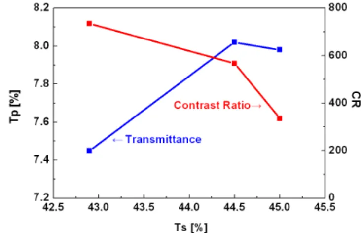
It is shown that the relation of panel transmittance (Tp) and CR as a function of Ts measured at 460 nm wavelength in figure 2. Transmittance and CR were measured at three discrete Ts of 42.9%, 44.5%, and 45.0% at 7 V operating voltage, respectively. It was shown that both the transmittance and CR are very sensitive to the Ts of the polarizer. Increase of Ts leads to an enhancement on the transmittance. In contrast, the CR drops sharply when Ts increases. When Ts of polarizer was increased from 42.9% to 45.0%, the panel transmittance was enhanced by 7.1%. But CR was abruptly decreased by ~50%. The trade-off relation between the transmittance and the contrast ratio is previously reported [6].
Fig. 2. Optical properties of panel with normal LC along the Ts of polarizer at 7 V.
To prevent that the CR was declined by Ts increasing, we introduced high ∆ε liquid crystal. The high ∆ε LC molecules are well-aligned perpendicularly compared to the normal LC due to the strong interaction in the same electric field. Figure 3 shows the contrast ratio plot of the panel with the applied voltage of 4.7 and 8 V for the off and on states, respectively. This graph was investigated with polarizer of 42.9% single transmittance. The CR of high ∆ε liquid crystal panel was larger than normal one with applied voltage 7 V. The saturation voltage of high ∆ε liquid crystal panel was lower than that of normal liquid crystal panel. So, the black luminance of high ∆ε LC was less than that of normal LC at the fixed voltage. By changing property of liquid crystal
P1-43 / S. H. Lim
IMID 2009 DIGEST • material, we can control the transmittance of panel. In
order to acquire high transmittance panel, the panel was fabricated with HT-POL and of high ∆ε liquid crystal.
Fig. 3. Voltage-dependent CR curve as different types of liquid crystals.
Table 2 represents the optical properties of the panels under various fabrication conditions. The transmittance of the panel with high transmittance polarizer and high ∆ε liquid crystal was 7.91%, improved 6% compared to that of the panel with normal polarizer.
TABLE 2. Optical properties in various conditions
Normal LC High ∆ε LC
Structure
Trans. CR Trans. CR Normal POL 7.45% 735.0 7.43% 1099.1
HT POL 8.00% 421.1 7.91% 732.7 The CR of the panel with high transmittance polarizer and high ∆ε liquid crystal was 732.7 at 7 V, was similar to the panel with normal polarizer and normal liquid crystal. The transmittance enhanced up to 7.91% by using both high transmittance polarizer and high ∆ε liquid crystal, along with good contrast ratio of 732.7 in the same structure.
4. Summary
The high transmittance panel was investigated by combining HT-POL and high ∆ε liquid crystal without changing panel structure. In this work, we achieved high transmittance with maintaining the contrast ratio
of conventional panel. The transmittance of the liquid crystal display panel fabricated by new polarizer was increased by 6% over that of the panel with conventional polarizer and liquid crystal.
Acknowledgement
Our thanks to Mr. Naoki Takahashi and collaborators of Nitto Denko Corporation, Ms. Dong Mi Song and collaborators of Merck Corporation for allowing us to refer development results and supply various samples.
5. References
[1] E. Jakeman and E. P. Raynes, Phys. Lett. A 39, 69 (1972).
[2] M. Jiao, Z. Ge, Q. Song, and S. T. Wu, Appl. Phys. Lett. 92, 061102 (2008).
[3] M. Schadt and W. Helfrich, Appl. Phys. Lett. 18, 127 (1971)
[4] S. T. Wu and C. S. Wu, Appl. Phys. Lett. 68, 1455 (1996)
[5] K. H. Kim, S. B. Park and J. Chen, SID Digest 29, 1085 (1998).