1. INTRODUCTION
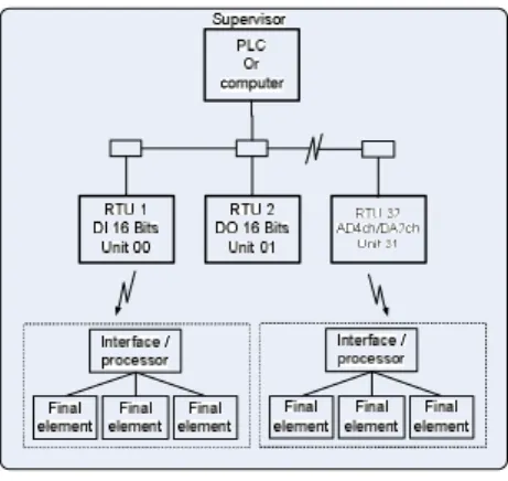
One of problems in industries is an installation for an automation system device such sensor, transducer, controller, and so on those are located in different areas. Such problem makes a difficulty for maintenance and installation. The aim of this research attempts to design a high performance controller with remote devices. One attractive is to group near devices in near place together to centralizes control This paper presents network device groups distributed through digital and analog Remote Terminal Unit Such devices are centralized by computer or PLC control and communicated with similar protocol through serial bus in IEC fiedbus RS485 standard. These networks, often referred to “data highways,” utilize twisted shielded-pair to carry high - speed communications data between the various Controller and RTUs microprocessor - based devices are connected to the network. The RTU network devices having three models are consist of Remote terminal Input 16 (RTI16), Remote terminal output 16 (RTO16) and Remote terminal AD/DA (RTAD). The number of RTUs that can be connected to data highway varies with the design of the network. The maximum of transmission systems are able expand to 32 RTUs.
Fig. 1 RTUs Network
The automatic control system in industries have many kinds of field device (e.g. sensor, actuators), and many kinds of process control. The fieldbus concept needed to combine the signals from many kinds of the process control equipment to
be the same signal by digital communication (1) the traditional communication standard known as this standard provides for point-to-point connection which consists of all information exchanged between field and control devices in both directions. The great number of field devices being used require a lot of cables. This is the problem in installation and maintenance and the documentation work as well.
The fieldbus concept is basically a digital communication, which is capable of interconnecting field devices with control system in any process control environment. The fieldbus communication architecture in the term of node will be used to refer to a field device. The fieldbus devices have wide varieties of field devices. There are simple devices such as the limit switches, relays, single-contact device and dumb actuators; the simple intelligent devices such as the transmitters, the receivers; the intelligent actuators; smart sensors; the complex devices such as the programmable controllers(PCs), PID and other loop controllers, etc. The fieldbus supervisor is the central controller that takes the total responsibility for initializing the bus, establishing what devices are attached to it and monitoring its activities. The fieldbus system are currently available in the market several venders. But none of them used an international standard, and only the IEC/ISA fieldbus communication system that is in the final stage of standardization the first line.
2.
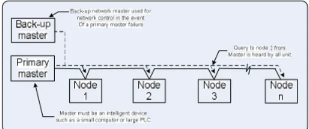
MASTER-SLAVE AND PEER TO PEER SYSTEMS.(2) The two basic network system formats offered by PCs manufacturers are master–slave and peer-to-peer. The master–slave system illustrated in Fig. 2 requires the use of an intelligent device, such as a computer or a large–size PCs, to manage all network communications between network devices. The programming of the master network device incorporates routines to individually address each slave device for the purpose of transmitting data between the addressed slave device and the master unit. Direct communication between slave devices is not possible. Information to be transferred between slaves must first be sent to the network master unit, which will in turn retransmit the message to the designated slave device. Master-slave systems offer the advantage of total control of network communications, but have the disadvantage of being solely dependent upon the master for all communications within the system. These types of systems often incorporate secondary backup network masters toDistributed control of Network devices through Remote Terminal
Suphan Gulpanich, Banharn Ploysuk,Viriya Kongratana,
Taweepol Suesut and Kitti Tirasesth
Department of Instrumentation Engineering, Faculty of Engineering. King’s Mongkut Institute of Technology Ladkrabang, 10520 Bangkok, Thailand.
(Tel : 66-2739-2407 Ext 110 E-mail: [email protected])
Abstract: One of problems in industries is an installation for an automation system device such sensor, transducer, controller, and so on those are located in different areas. Such problem makes a difficulty for maintenance and installation. The aim of this research attempts to design a high performance controller with remote devices. One attractive is to group near devices in near place together to centralizes control. This paper presents network device groups distributed through digital and analog Remote Terminal Unit (RTUs). Such devices are centralized by computer or PLC control and communicated with similar protocol through serial bus. Our scheme, there are many advantages such as, saving both time and cost,convenience compared to other ways.
operate the network in the event of primary master failure
Fig.2 Master-slave PLC communication
Peer-to-peer systems do not incorporate a master to control the network. Instead each network device has the ability to request use of, and then take control of, the network for the purpose of transmitting or requesting information from other network devices. This type of network communication scheme is often described as a baton or token passing system, since control of the network can be thought of as a baton that is passed from unit to unit.
The advantages and disadvantages of the peer-to-peer system are directly opposite those the master-slave system. Since each network member has the right to use the data link, control of which devices use the network, how long a device uses the network, and the type of information passed on the network is harder to achieve. This system does have the distinct advantage of remaining in operation even with one or more units out of service. Error codes will usually be generated from active units attempting communication with faulted units, but communications can continue between active remaining units Fig. 3 illustrates the configuration of a peer-to-peer communications network.
Fig.3 Peer-to-Peer Communication network
3. DISTRIBUTED CONTROL AND
NETWORKS(2)
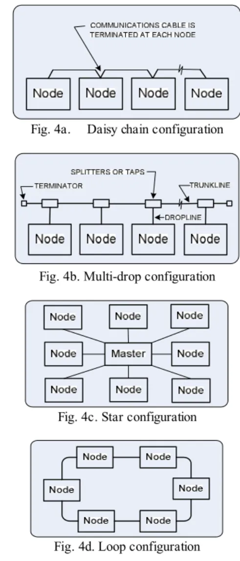
A distributed control system (DCS) is one of which several controllers are operating simultaneously and co-operatively. Such systems can be divided into tightly coupled multiprocessor systems sharing a common bus back plane and loosely coupled systems where processor-based controller are located at the points of control and exchange information via some kind of input/output port. A system of loosely coupled processor-base systems (e.g.computer ,PCs etc.) interconnected together is called a network. Several physical arrangements of communications networks with current systems are possible. Daisy-chain arrangements directly tie the network device module to the communications cable, as depicted in Fig. 4a. Alternately some systems allow the use of “tee taps” on the main cable or trunk line, as illustrated in Fig. 4b. This type of connection arrangement is often referred to as a “multi-drop system.” A module is connected to the trunk line’s tee tap via a short length (usually 500 feet maximum) of drop cable. The daisy-chain configuration might be thought of as a multi-drop arrangement with “zero-length” drops from the trunk line. A third arrangement not often found is the “star” configuration
of Fig. 4c. This system has each device module wired back to a central distribution point, and is used primarily in master-slave-type applications. Finally the closed-loop system of Fig. 4d. is also available. One advantage of the closed-loop system is that network communications are usually not lost unless the loop is severed in two locations. lt should be noted that many of the available systems may be a combination of two or more of the simple arrangements listed above, or a system may have the flexibility to be configured into any one or more of the listed simple configurations, depending on the user’s needs and requirements.
Fig. 4a. Daisy chain configuration
Fig. 4b. Multi-drop configuration
Fig. 4c. Star configuration
Fig. 4d. Loop configuration
4.
NETWORK COMMUNICATION TRANSACTIONS. Depending on the type of network being implemented, either master-slave or peer-to-peer, several forms of network device transactions are possible. This paper present master-slave systems are usually offer either query/ response or broadcast-type transactions to be implemented between devices. The query/ response transaction of the master-slave system is depicted in Fig. 5 The communications network master unit selects the slave device to be interrogated and transmits a query message to that slave over the network. All slave units on the network actually receive the message, but only the slave unit in question will decode the transmission and pass it on to its PC. The slave node then carries out the instructions of the message and passes a response message back to the master, indicating the completion of the instruction along with any required response data.Fig. 5 Master-slave Query/Response Transaction
A variation of the query/ response transaction is the broadcast transaction illustrated in Fig. 6This type of transaction is similar to the query/ response transaction except that all slave node decode the transmission from the master. Each slave node will carry out the instructions of the message However, none of the slaves will send a confirmation response back to the host master.Fig. 6 Master-slave Broadcast Transaction
5. Hard ware design
Remote terminal units are distributed through network device group, centralized by computer control and communicated with similar protocol through serial bus in IEC fieldbus RS485 standards. These networks, often referred to as “data highways”, utilize twisted shielded-pair to carry high speed. Communications data between the various Controller and RTUs microprocessor - based devices connected to the network. The RTU network devices consisted of three models, Remote terminal Input 16 (RTI16), Remote terminal output 16 (RTO16) and Remote terminal AD/DA (RTAD). The number of RTUs that can connected to data communication network varies with the network design. The maximum of modules are able to expand to 32 units. RTU designed by microcontroller MSC51 is CPU that operated with Crystal frequency 11.0592 MHz. RAM size 4 Kbytes, ROM size 256 bytes. Max 192 A/D chip support 10 bits 8 channel and 2 Chips 0800 D/A 8bits 1 channel depict fig.7a
Fig. 7a. block diagram of RTU units
Depict Fig. 7b. RTI16 Circuit board , 16 bits digital input Opto-Isolated , DC. Voltage sink input circuit
Fig. 7b. Remote terminal Input(RTI16)
Depict Fig. 7c. RTO16 Circuit board , 16 bits digital
output Opto-Isolated ,
NPN transistor outputFig. 7c. Remote terminal Input(RTO16)
Depict Fig. 7d. RTAD Circuit board ,4 channels input ,
2channel output, all of them are current 4-20mA.
Fig.7d. Remote terminal Input(RTAD)
5. RTUs OPERATION AND PROTOCOL DESIGN
5.1 RTUs operation
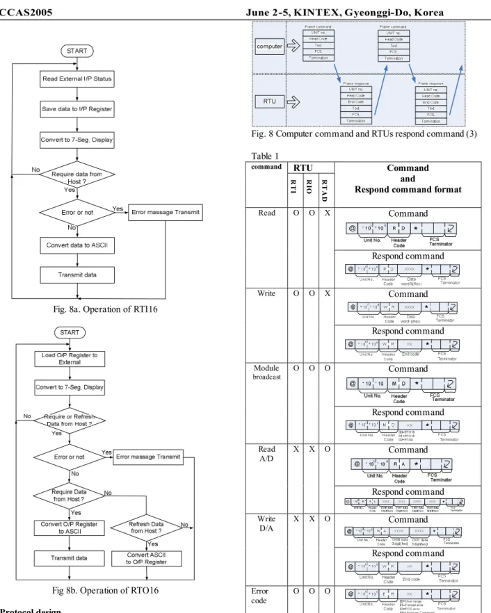
The operation of RTI16 and RTO16 in Fig.8a and 8b,
respectively. The RTAD operation is similar to RTI16
and RTO16.
Fig. 8a. Operation of RTI16
Fig 8b. Operation of RTO16 5.2 Protocol design
The control network have only one master is the central controller and all RTUs are slave nodes, also called “device net”. There are different stations for identification and distributed to different areas. The query/respond transaction between master-slave is called “protocol” . This paper presents protocol design in TEXT ASCII through data highway. The query from computer is called “ command” and respond from node is called “respond command”, as illustrated in table 1
Fig. 8 Computer command and RTUs respond command (3) Table 1 RTU command RTI RI O RTAD Command and
Respond command format Command Read O O X Respond command Command Write O O X Respond command Command Module broadcast O O O Respond command Command Read A/D X X O Respond command Command Write D/A X X O Respond command Error code O O O
“O” is selected and “X” is deselected
6. IMPLEMENTATION
In this experiment has
network device groups distributed through analog Remote Terminal Unit Such devices are centralized by computer control through serial bus in IEC fieldbus RS485 standard. There are twoRTAD
nodesdistributed in the network, the first RTAD is station #00
for Flow and Level Plant model and another RTAD is
station #01 for Pressure Plant model as depicted in Fig.
9a, the distributed fieldbus network.
Fig.9a Computer control through RTAD fieldbus network
Flow and Level Plant model and process control in
block diagramare illustrated in Fig.9b and 9c,
respectively.
RTAD station #00 connects to final
element in
Fig. 9d. Software control application which develop on Delphi compiler for monitoring, which is the result of processes showed in Fig.9eFig. 9b. Flow and Level control Plant model
Fig. 9c. Block diagram of Flow and Level control
Fig. 9d. RTAD with final element
Fig. 9e. Software control application
In the same way, Pressure Plant model is similar to Flow and Level Plant model, except RTAD is station #01 as depicted in
Fig.10a-10c.
Fig. 10a. Air Flow and Pressure Plant model
Fig. 10b. Block diagram of Air Flow and Pressure control
Fig. 10c. Software control application
7. Conclusion
Control time will be delayed if more node distribution and longer distance cable in network, this effect to speed response, but it easier to automation control in distributed plants. RTUs hardware in 3 models developed in this research are used in PLC and Process control laboratory in Instrumentation Engineering Department. Even these RTUs are not convenient to program as the imported controllers, the students can learn more techniques from them e.g. developing control program according to the theory ect. This will let the students have more skills with economical controllers while the imported ones can not deliver those skills.
REFERENCES
(1) Alan J.Crispin, “Programmable Logic Controller and
their Engineering Application”, Second Edition, the
McGraw-Hill Companies.1997.
(2) Robert E.Wilhelm,JR.“ Programmable Controller
Handbook” , Copyright.1985
(3) SYSMAC CQM1/CPM1”Programmable Controllers” Programming Manual , OMRON,Revised June 19