1. INTRODUCTION
The induction motors have been extensively applied in industry because of the advantages of simple construction, ruggedness, reliability, the minimum maintenance and low cost. This kind of motor has a very nonlinear system. In addition two main parameters of induction motor which are defined as torque and flux must be decoupled from each other for controlling separately. The decoupled control approaches, such as field-oriented control and nonlinear state feedback linearizing technique have been widely used in the design of induction motor derives for high-performance applications.
In the field-oriented method, the decoupled relationship is obtained by means of a proper selection of state coordinates, under the hypothesis that the rotor flux is kept constant [1], [2]. Nonlinear-state feedback control utilizes the feedback-linearization approach, which can achieve input–output decoupling control and good dynamic performance for induction motors [3], [4]. However, though the decoupled condition is always satisfied, the parameters of the controlled plant must be precisely known and accurate information on the rotor or secondary flux is required.
Sliding mode control (SLMC) has been shown to be an effective way for controlling electric drive systems. It is a robust control because the high-gain feedback control input cancels nonlinearities, uncertainty parameters, and external disturbances. It also offers a fast dynamic response, a stable control system and an easy hardware/software implementation. This control strategy offers some drawbacks associated with the large torque chattering that appears in a steady state, which may excite mechanical resonance. Fuzzy-logic, first proposed by L. A. Zadeh, has recently received a great deal of attention. The easy way of defining a fuzzy controller by rules with an obvious physical meaning has helped to expand this control technique. When it is applied to control nonlinear systems, this nonlinear control strategy has shown better results than classical controllers do [5].
In this paper at first torque and flux are decoupled and nonlinear terms of motor is cancelled by applying feedback
linearizing method. The main objective of this paper is to implement PI fuzzy controller which its inputs are sliding surfaces which are made of error dynamics. Main benefits of this approach are its robustness to system disturbance and input noise and uncertainty in system.
2. Induction motor model
Under assumption of linearity a three phase induction motor model in d-q stationary reference frame can be described by the following differential equations [6]:
( )
x
u
g
1u
g
2f
x
&
=
+
ds+
qs (1) Wherex
=
[
x
1x
2x
3x
4]
T=
[
i
dsi
qsψ
dsψ
qs]
( )
− + − − + − − + + − = 4 r 3 r 2 r m 4 r 3 r 1 r m 4 3 r 2 4 r 3 1 x T 1 x w x T L x w x T 1 x T L x x w x x w x x x f β γ α γ β α (2) T 2 T 1 0 0 L 1 0 g 0 0 0 L 1 g = = σ σ (3) σ σ σ β α L L L R L L L R L R 2 r m r 2 r 2 m r s + = = , (4) r 2 m s r mL
L
L
L
L
L
L
−
=
=
σ σγ
,
(5) Also Torque and flux are described as:(
dr qs qr ds)
r m e i i L L 2 p 2 3 T = ψ −ψ (6)(
2)
qr 2 dr 2 r ψ ψ ψ = + (7)ADAPTIVE PI FUZZY CONTROLLER FOR INDUCTION MOTOR USING FEEDBACK LINEARIZING METHOD
Dr. Muhammad Reza Jahed Motlagh*, and Majid Hajatipour **
* Department of Electrical Engineering, Iran university of science and technology, Tehran, Iran (E-mail: [email protected] )
** Department of Electrical Engineering, Iran university of science and technology, Tehran, Iran (E-mail: : [email protected])
Abstract: In this paper an adaptive fuzzy PI controller with feedback linearizing meth od is implemented to controlling flux and torque separately in induction motor. In this paper first decoupling of torque and flux which are outputs to be controlled, is achieved by using feedback linearization methodology. Then for reducing the effect of noise and rejection of disturbance, main part of controller which is adaptive PI fuzzy controller, is designed. Coefficients of PI controller are determined by defined fuzzy rules due to error dynamic. Inputs of fuzzy system are defined sliding surfaces which consist of torque and flux errors. The main contribution of this paper is effect reduction of noise and disturbance on torque and flux which is based on fuzzy logic and nonlinear control. At last the effectiveness of the proposed control scheme in presence of noise and load disturbance is simulated and comprised to applying sliding
method. The results verify better effectiveness of the proposed method for effect reduction of noise and disturbance.
Fig.1: system configuration of proposed controller
As it is clear there is nonlinear relationship between torque and flux and state variables and it is difficult to control them separately. So feedback linearizing control (FLC) is applied to decouple them.
3. Controller design
Figure.1 presents main schematic of proposed controller.
3.1 Decoupling torque and flux
In this part of paper in order to control torque Te and square rotor fluxψr2, the output equations are chosen as:
( )
( )
(
(
)
)
+ − = = = 2 qr 2 dr ds qr qs dr r m 2 r e 2 1 i i L L 2 p 2 3 T x h x h y ψ ψ ψ ψ ψ (8)To obtain linear relationship between output and states of coordinate transformation by using feedback linearization a subset of the new state variables of the coordinate transformation can be chosen according to Eq.(8). So definition of the new coordinates is given as below:
( )
( )
( )
( )
( )
+ = = qs ds 2 f 2 g 2 f 1 g 1 2 g 1 1 g 2 2 f 2 f 1 f 3 2 1 u u x h L L x h L L 0 x h L x h L x h L h L h L h h h y & & & (9) Where h( )
x T h( )
x andh3( )
x h2( )
x 2 r 2 e 1 = , =ψ = & andalsoLfh
( )
x is the Lie derivative of a function h( )
x along avector fieldf
( )
x =[
f1( )
x,f2(x),...,fn( )
x]
.By using FLC method to decouple the control inputs, the resulting system is:
+ = = qs ds 2 2 f 3 1 f 3 2 1 u u 0 1 0 0 1 0 h L h h L h h h y ˆ ˆ & & & (10)
And the linear feedback is defined as:
( )
( )
( )
( )
+
+
=
qs 1 2 g ds 1 1 g qs 2 f 2 g ds 2 f 1 g qs dsu
x
h
L
u
x
h
L
u
x
h
L
L
u
x
h
L
L
u
u
ˆ
ˆ
(11) As it is clear, controller generates control signals uˆds andqs
uˆ and by applying Eq. (11) main control signals
u
dsand
u
qs are produced.To perform good Tracking dynamic, the model is defined as: + − − − = ref 2 ref 2 m 1 m 3 m 2 m 1 m 3 m 2 m 1 m 3 m 2 m 1 m T a 0 0 0 0 a h h h a a 0 1 0 0 0 0 a h h h ψ & & & (12)
Where
a
m1,a
m2anda
m3 are positive constants. Alsotracking errors are:
3 m 3 3 2 m 2 2 1 m 1 1
h
h
e
h
h
e
h
h
e
=
−
,
=
−
,
=
−
(13) 3.2 PI fuzzy controllerIn this section main part of this paper is presented. At first relationship between uˆds, uˆqs control signals and
qs ds u
u~ , ~ which are produced by PI controller system, due to Eq. 10 are: qs 1 1 1 1 qs lfh hm ke u uˆ =− + & − −~ (14) ds 2 3 2 2 3 2 2 ds
l
fh
h
m
k
e
k
e
u
u
ˆ
=
−
+
&
−
&
−
−
~
(15) Then the dynamics of the error system with presence of inaccuracies in system modeling or measurements noise or disturbance in load which is presented bydˆ ,1 dˆ2 are:0
d
u
e
k
e
1+
1 1+
qs+
ˆ
1=
~
&
(16)0
d
u
e
k
e
k
e
&
2+
2&
2+
3 2+
ˆ
ds+
ˆ
2=
&
(17) So:( )
t
(
u
d
)
( )
k
t
e
1=
~
qs+
ˆ
1exp
−
1 (18)( )
t
(
u
d
)
[
( )
t
( )
t
]
e
1 2 1 2 2 ds 2α
α
α
α
exp
exp
ˆ
~
−
−
+
=
(19)Which its coefficients are:
2
k
4
k
k
3 2 2 2 2 1−
±
−
=
α
α ,
(20) According to Eq. 18 and 19, insurance of stability is achieved by choosing k1f0 and also k ,2 k3 are selected soα ,1α2 have negative signs.Fuzzy system generates coefficients of PI controller (
k
P′
,
k
I′
,
k
P′′
,
k
I′′
).dt
e
k
e
k
u
~
qs=
P′
1+
I′
∫
1.
(21)dt
e
k
e
k
u
~
ds=
P′′
2+
I′′
∫
2.
(22) For appropriate tracking, fuzzy system input signals are defined as sliding surfaces:1 1e kˆ
PI-Fuzzy
Controller-1
PI-Fuzzy
Controller-2
2 2 2e
e
k
ˆ
+
&
Eq. (14), (15)
&
Eq. (11)
refT
s
1 2s
qsu~
dsu~
qsu
dsu
IMModel
+ - + - ref 2ψ
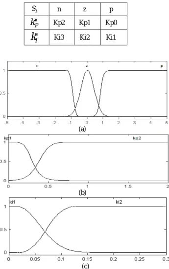
Table I: Rules of PI-Fuzzy controller-1
(a)
(b)
(c)
Fig.2: Membership functions of PI-Fuzzy controller-1. (a) Input memberships. (b), (c) output memberships
TableII: Rules of PI-Fuzzy controller-2
2 2 2 2 1 1 1 ke s ke e s =ˆ , =ˆ +& (23) Presence of inaccuracies (dˆ ,1 dˆ ), yields to increase in 2
defined errors and sliding surfaces which are inputs of fuzzy system. So fuzzy system senses inaccuracies and consequently regulates its outputs u~ds,u~qs to canceling effect of inaccuracies which this regulation is based on experimental knowledge that is presented in tables I and II.
0 d u 0 d uds+ 1→ qs+ˆ2→ ~ , ˆ ~ (24)
And consequently it causes:
0 e 0
e1→ , 2→ (25) Membership functions are presented in Fig.2 and Fig. 3. PI controller coefficients adapts due to defined errors by fuzzy system.
(a)
(b)
(c)
Fig.3: Membership functions of PI-Fuzzy controller-2. (a) Input memberships. (b), (c) Output memberships
Fig. 4: Torque of motor (Top), Reference torque (Button), in presents of noise and disturbance
4. Simulation
In this part, proposed controller is implemented on induction motor model by simulation. Fig. 4 and 5 represents torque and flux which are controlled by proposed controller in presence of measured noise and disturbance in output torque and flux at 25th second. As it is seen proposed approach controller has a good action in noise effect reduction and disturbance effect cancellation. In order to better evaluation
1
S n z p
P
k
′
Kp2 Kp1 Kp0I
k
′
Ki3 Ki2 Ki12
S na2 na1 a0 Pa1 Pa2
P
k
′′
Kp2 Kp1 Kp0 Kp1 Kp2I
the performance of proposed method, it is compared to the sliding mode controller (SLMC) and it is implemented to control torque and flux. By using sliding method the control signals due to Eq. 10 are:
( )
1 2 1 1 1 1 ˆ lfh hm ke k sat s uqs =− + & − − (26)( )
2 5 2 4 2 3 3 2 2ˆ
l
fh
h
m
k
e
k
e
k
sat
s
u
ds=
−
+
&
−
&
−
−
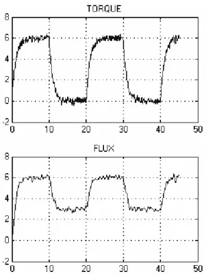
(27) Simulated results are shown in Fig. 9. By comparing the proposed controller results to sliding method it is clear that proposed controller acts very better in presence of noise and disturbance.5. Conclusions
In this paper an adaptive fuzzy PI controller with feedback linearizing method is implemented to controlling flux and torque separately in induction motor. First decoupling of torque and flux which are outputs to be controlled, is achieved by using feedback linearization methodology. Then for reducing the effect of noise and rejection of disturbance or inaccuracy in modeling, main part of controller which is adaptive PI fuzzy controller, is designed. Coefficients of PI controller are determined by defined fuzzy rules due to error dynamic. The main contribution of this paper is effect reduction of noise and disturbance on torque and flux which is based on fuzzy logic and nonlinear control.
Appendix. A
M
N
T
H
L
L
H
L
H
L
R
R
s
rad
w
r m r s r s r.
96
.
14
,
18
.
412
96
.
822
,
489
.
44
,
0215
.
242
.
,
253
.
,
253
.
68
.
4
,
58
.
4
,
/
98
.
154
=
=
=
=
=
=
=
=
=
Ω
=
=
α
β
γ
σFig. 5: Flux of motor (top), Reference Flux, (button) in presents of noise and disturbance
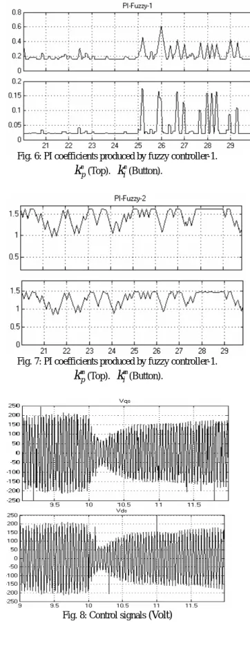
Fig. 6: PI coefficients produced by fuzzy controller-1.
p
k
′
(Top).k
i′
(Button).Fig. 7: PI coefficients produced by fuzzy controller-1.
p
k
′′
(Top).k
i′′
(Button).Fig. 9: Torque (Top) and flux (Button), in presents of noise Of motor by sliding mode controller
References:
[1] C. C. Chan and H.Wang, “An effective method for rotor resistance identification for high-performance induction motor vector control,” IEEE Trans. Indust. Electron., vol. 37, pp. 477–482, 1990.
[2] F. J. Lin, H. M. Su, and H. P. Chen, “Induction motor servo drive with adaptive rotor time-constant estimation,” IEEE Trans. Aerosp. Electron. Syst., vol. 34, pp. 224–234, 1998.
[3] W. J.Wang and C. C.Wang, “Composite adaptive position controller for induction motor using feedback linearization,” IEE Proc. Contr. Theory Applicat., vol. 145, pp. 25–32, 1998.
[4] H. J. Shieh and K. K. Shyu, “Nonlinear sliding-mode Torque control with adaptive backstepping approach for induction motor drive,” IEEE Trans. Indust. Electron., vol. 46, pp. 380–389, 1999.
[5] F. Barrero, Barrero, A. González, A. Torralba, E. Galván, " Speed Control of Induction Motors Using a Novel Fuzzy Sliding-Mode Structure", IEEE Trans On Fuzzy Systems, Vol. 10, No. 3, pp. 375-383, June 2002. [6] F. Chen, M. W. Dunnigan, " Feedback Linearization Sliding-Mode Torque Control of an Induction Machine", IEE Confs on Power Electronics, Machine and Drives, April 2002.