P1-53 / S. D. Ahn
IMID 2009 DIGEST •
Abstract
Optical properties of white organic light-emitting devices (WOLEDs) fabricated utilizing a phosphor layer acting as a color conversion layer were investigated. The WOLEDs were achieved due to the enhancement in the color conversion efficiency of the phosphor layer, and the chromaticity coordinates of WOLEDs were (0.29, 0.33).
1. Introduction
White organic light-emitting devices (WOLEDs) have attracted a great deal of interest due to their potential applications in full-color displays, backlights for liquid crystal displays, and solid-state lighting sources [1-6]. Because the color mixing method for fabricating WOLEDs uses multiple emitters in a single WOLED, the structures of the WOLEDs are very complicated, and the manufacturing cost of the WOLEDs is very expensive. However, the color conversion method using several phosphor layers has several advantages of simple structure, low production cost, and high stability. Even though some studies on the fabrication of WOLEDs consisting of blue phosphorescent organic light-emitting device (OLED) with a color conversion phosphor layer have been performed [7-9], their efficiencies, color coordinates,
and color rendering indices (CRI) are insufficient to use backlight applications or general lighting sources.
This paper reports data for the optical properties of WOLEDs fabricated utilizing a CaAl12O19:Mn4+ phosphor layer acting as a red color conversion layer. Electroluminescence (EL) and photoluminescence (PL) measurements on the blue phosphorescent OLEDs and the CaAl12O19:Mn4+ phosphor layer were carried out to investigate the color conversion efficiency of the phosphor layer. Scanning electron microscopy (SEM) measurements were performed to clarify the difference of the color conversion efficiency for different printing methods of the phosphor layer.
2. Experimental
Deep blue phosphorescent OLEDs with a tris((3,5-difluoro-4-cyanophenyl)pyridine)iridium (FCNIr)-doped 3,5-bis(N-carbazolyl)benzene (mCP) emitting layer (EML) were deposited on indium-tin-oxide (ITO)-coated glass substrates. After CaAl12O19:Mn4+ compounds were prepared by a conventional sol-gel process, they were fired in a crucible furnace at 1400 K for 2 h in air. The fired phosphors were printed on the glass substrates by
Electroluminescence properties of white organic
light-emitting devices fabricated utilizing a CaAl
12O
19:Mn
4+phosphor layer acting as a color conversion layer
S. D. Ahn
1, D. C. Choo
1, T. W. Kim
1*, J. Y. Lee
2, J. H. Park
3, M. S. Kwon
3, C.
Chu
4, and J. Ha
41Research Institute of Information Display, Division of Electronics and Computer Engineering, Hanyang University, Seoul, Korea
2Department of Polymer Science and Engineering, Dankook University, Gyeonggi-do, Korea 3Department of Materials Science and Engineering, University of Seoul, Seoul, Korea
4Technology Center, Samsung Mobile Display CO., LTD, Yongin, Korea
P1-53 / S. D. Ahn
• IMID 2009 DIGEST
using two kinds of methods. While the reference device did not contain a phosphor layer, the color conversion phosphor layers were printed on the opposite side of the glass substrate in devices I and II. After the phosphor layer in device I was printed by using transparent epoxy resin, it was dried for 20 h in air. Subsequently, the phosphor layer in device II was printed by using a vehicle solution and heated for 1.5 h at 450oC.
3. Results and discussion
Figure 1 shows the EL spectrum of the blue phosphorescent OLEDs with an FCNIr-doped mCP EML and the PL spectrum of the CaAl12O19:Mn4+ phosphor thin film. The EL spectrum of the blue phosphorescent OLEDs shows two dominant peaks at 452 and 478 nm. The PL spectrum of the CaAl12O12:Mn4+ phosphor layer excited by 470 nm shows three dominant peaks at 640, 653.6, and 663.6 nm, which originates from the 2E → 4A
2 transitions of Mn4+. 400 500 600 700 800 (b)
IN
TE
N
S
IT
Y
(
arb
. un
it
s)
WAVELENGTH (nm)
(a)Fig. 1 (a) Electroluminescence spectrum of the blue phosphorescent OLEDs and (b) photoluminescence spectrum of the phosphor thin film.
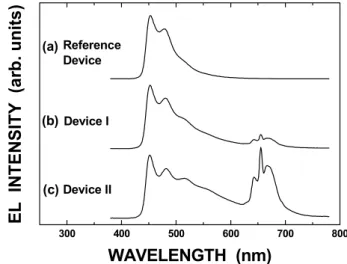
Figure 2 shows the EL spectra of the blue phosphorescent OLEDs with and without a CaAl12O19:Mn4+ phosphor layer. The peaks around 650 nm of the EL spectra for devices I and II indicate that the blue color emitted in the EML of the blue phosphorescent OLEDs is converted into the red color by the color conversion layer. The Commission Internationale de l’Eclairage (CIE) chromaticity coordinates for reference device, device I, and device II are (0.15, 0.17), (0.21, 0.27), and (0.29, 0.33), respectively. The CIE coordinates for device II are more close to white color coordinates of (0.33, 0.33). Because the residual materials on the crystal particles interrupt the blue light absorption of the phosphor crystal particle, the color conversion rates between devices I and II are different. The SEM images for the phosphor layer of devices I and II show the existence in the residual materials between the phosphor crystal particles. Because almost all of the vehicle solution of device II vaporizes during a heat process, the color conversion efficiency of device II increases, resulting in an emission of near white color.
300 400 500 600 700 800 (c) (b) Reference Device Device II Device I EL IN T E N S IT Y ( a rb . u n it s ) WAVELENGTH (nm) (a)
Fig. 2 Electroluminescence spectra for (a) reference device (b) device I, and (c) device II.
4. Summary
The electroluminescence properties of the WOLEDs with a CaAl12O19:Mn4+ phosphor layer
P1-53 / S. D. Ahn
IMID 2009 DIGEST • acting as a color conversion layer were investigated.
While the color conversion efficiency of device I prepared by using a transparent epoxy resin and without performing a heat process was decreased due to the residual epoxy resin, that of device II prepared by using a vehicle solution and with performing a heat process dramatically increased, resulting in the achievement of device II with a white color. These results indicate that the CRI of the WOLEDs can be improved by using the red phosphor layer acting as a color conversion layer.
Acknowledgement
This work was supported by the Korea Science and Engineering Foundation (KOSEF) grant funded by the Korea government (MEST) (No. R0A-2007-000-20044-0).
5. References
1. B. C. Krummacher, V.-E. Choong, M. K. Mathai, S. A. Choulis, F. So, F. Jermann, T. Fiedler, and M. Zachau, Appl. Phys. Lett. 88, pp113506-1 - 113506-3 (2006).
2. S. Reineke, F. Lindner, G. Schwartz, N. Seidler, K. Walzer, Bjőrn Lűssem and K. Leo, Nature, Vol. 459 pp34 (2009)
3. S-J. Su, E. Gonmori, H. Sasabe and J. Kido, Adv.
Mater. 20, pp 4189 (2008)
4. G. Schwartz, K. Fehse, M. Pfeiffer, K. Walzer and K. Leo, Appl. Phys. Lett. 89, pp083509 (2006) 5. G. Schwartz, M. Pfeiffer, S. Reineke, K. Walzer and
K. Leo, Adv.Mater. 19, pp3672 (2007)
6. B. W. D`Andrade, R. J. Holmes and S. R. Forrest,
Adv. Mater. 19, pp624 (2004)
7. S. C. Allen and A. J. Steckl, Appl. Phys. Lett. 92, pp143309-1 - 143309-3 (2008).
8. E. L. Williams, K. Haavisto, J. Li, and G. E. Jabbour, Adv. Mater. 19, pp197 (2007)
9. Y. Sun and S. R. Forrest, Appl. Phys. Lett. 91, pp 263503 (2007)