International Journal of Advanced Robotic Systems
Interactive Multi-Resolution Display Using
a Projector Mounted Mobile Robot in
Intelligent Space
Regular Paper
Jeong-Eom Lee
1, Jiyoung Park
1, Gon-Soo Kim
2, Joo-Ho Lee
3and Myoung-Hee Kim
1,4,*1 Center for Computer Graphics and Virtual Reality, Ewha Womans University, Seoul, Korea 2 Mechatronics, Korea University, Seoul, Korea
3 School of Information Science & Engineering, Ritsumeikan University, Shiga, Japan 4 Department of Computer Science & Engineering, Ewha Womans University, Seoul, Korea
* Corresponding author E-mail: [email protected]
Received 20 Aug 2012; Accepted 10 Oct 2012
DOI: 10.5772/54232
© 2012 Lee et al.; licensee InTech. This is an open access article distributed under the terms of the Creative Commons Attribution License (http://creativecommons.org/licenses/by/3.0), which permits unrestricted use, distribution, and reproduction in any medium, provided the original work is properly cited.
Abstract In this paper, we propose a novel interactive multi‐resolution display system. The proposed system is based on a projector‐mounted mobile robot in an Intelligent Space. The Intelligent Space can calculate the location of the region of interest (ROI) by recognizing the user’s pointing gesture. The steerable projector mounted on the mobile robot can improve the brightness and resolution of the ROI of a large image projected by a stationary projector installed in the Intelligent Space. In the proposed system, the user is not required to hold any apparatuses for interacting with the display. Additionally, the proposed system is easy to use because it is designed with the natural and intuitive hand movement of user in mind. In the experiments, we demonstrate the feasibility of the proposed system.
Keywords Interactive multi‐resolution display, Steerable projector mounted mobile robot, Ubiquitous Display, Intelligent Space, Pointing gesture
1. Introduction
General use of projectors has presented visual information to a passive audience in a fixed place because the projectors can generate images that are larger in size than LCD monitors. However, the advent of novel sensing and display technology has encouraged the employment of projectors in constructing novel forms of displays. Since a projector is decoupled from a screen, the projector can project an image onto not only a planar surface, but also many types of non‐planar surfaces [1, 2]. Moreover, one large‐scale seamless display can be created and additional information can be effectively superimposed on the display surface by using multiple projectors [2, 3]. Over the last few years, projector technology has advanced at a dramatic rate: tiny mobile projectors are now commercially available and a projector has even been embedded in a mobile phone and become applicable to the field of wearable computing [4]. However, if we consider the typical use of projectors that allows users to view large visual information, the
brightness and resolution of projectors is not enough to show every detail. When the size of the projected image becomes large, the Dots Per Inch (DPI), brightness and contrast of the projected image decrease. One of solutions is tiling up projectors or LCD screens, but this is inefficient because of costs.
To cope with this problem, an additional projector should be combined to provide a small overlay of bright and good‐resolution images on a large low‐resolution image that is projected by the other projector. This approach can improve the brightness and resolution of a region of interest within a larger image. The second projector can also provide additional information.
In [5], a personal projected display system called Escritoire was introduced. This system used two overlapping projectors to create a projected desk display. One projector used for a large low‐resolution region fills an entire desk, while the other projector used for a small high‐resolution region shows the user’s focus of attention. The interactive multi‐resolution tabletop (i‐m‐Top) system presented in [6] also used two projectors. The i‐m‐ Top could provide a high‐resolution image with a steerable projector, while providing a low‐resolution image with a wide‐angle fixed projector. These systems are table‐type multi‐resolution systems. While a high‐ resolution area of Escritoire was fixed, the i‐m‐Top was not.
e‐Fovea described in [7] is a large‐scale and high‐
resolution monitoring system which combines multi‐ resolution display with multi‐resolution video capture for visual monitoring. The multi‐resolution output system of
e‐Fovea consists of a fixed projector and a steerable
projector. The fixed projector projects onto a large wall surface, providing peripheral vision at low pixel density. The steerable projector projects onto a small, embedded region at a much higher pixel density [7].
More recently, the use of mobile projectors has drawn much research attention from those working on multi‐ resolution displays [8]. In particular, in [8], a vision‐based method was presented for tracking a mobile projector, which involves projecting a detailed image onto a large projected image.
Besides, there were several systems that combined a projector and a LCD screen. In [9], the focus plus context (F+C) screen was introduced. The F+C screen is a multi‐ resolution display that integrates a fixed LCD with a projection screen. In [10], a slim tablet PC was used to show high‐resolution images.
In this paper, we propose a novel interactive multi‐ resolution display system. The proposed system is based on a projector‐mounted mobile robot in the Intelligent
Space (iSpace). The steerable projector mounted on a mobile robot is used to enhance a small region of a large image projected by a stationary projector installed in the iSpace. The iSpace calculates the location of the region of interest (ROI) in the large image by recognizing the user’s pointing gesture. Then, the projector‐mounted mobile robot projects the ROI images onto the screen surface where the user is pointing to. Since the iSpace can also recognize the user’s gestures, the user and the iSpace can communicate with each other by the projector‐mounted mobile robot.
In our system, the user is not required to hold any apparatuses for interacting with the display. Additionally, the suggested gesture interface is easy to use even for beginners because it was designed using the natural and intuitive hand movements of users.
In the rest of this paper, we will first describe the projector‐mounted mobile robot in the iSpace in section 2. Section 3 presents the interactive multi‐resolution display and gesture interface. The experimental result is described in section 4. Finally, we summarize and discuss our results in section 5. For simplicity, in the remaining sections of this paper, the large image projected by the stationary projector will be termed the “large display” and the inset image projected by the steerable projector on the mobile robot will be termed the “small display”.
2. Projector‐Mounted Mobile Robot in the Intelligent Space
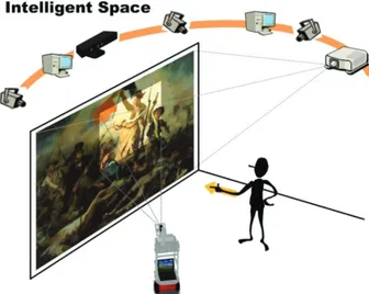
Figure 1 shows a schematic outline of our interactive multi‐resolution display system using a projector‐ mounted mobile robot in the iSpace. We call the projector‐mounted mobile robot “Ubiquitous Display” (UD). The UD can be used to enhance a small region of a large display.
Figure 1. Interactive multi‐resolution display system
The iSpace [11] is a room or an area that is equipped with a lot of sensors. It is a well‐configured environment to
understand what happens to people in it and to provide various services for humans and robots. In the iSpace, a person is monitored by distributed sensors connected via a network, which is called a Distributed Intelligent Network Device (DIND) [11]. A DIND is composed of three basic elements: a sensor, a processor and a communication device. Many DINDs are spread out over the space and enable the iSpace to recognize objects and events. Because the DINDs share information with each other by mutual communication through the network, they contribute to the more sophisticated recognition ability of the iSpace. Moreover, the iSpace can provide useful services for people by using agent robots and the information obtained by DINDs.
The UD is a physical agent robot in the iSpace. The UD consists of five components: a projector, a pan‐tilt mechanism, a power supply, a mobile robot and a laptop as shown in Figure 2. The main role of the UD is to project visual information to where the user is pointing [12, 13].
Figure 2. Ubiquitous Display (UD)
3. Interactive Multi‐Resolution Display Using Gestures
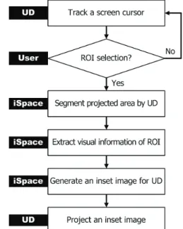
Figure 3 shows the process by which the UD projects an inset image on the Region of Interest (ROI) of the user. Firstly the iSpace recognizes the user’s ROI and a command by using a RGB‐Depth camera (Kinect camera) which is installed in the iSpace. Next, the iSpace detects the projection area of the UD and adjusts it to the user’s ROI. Then the UD projects an inset image with fitted into the ROI by perspective warping. 3.1 Determination of the Projection Area The UD can produce a small display of better brightness and resolution in the ROI than the large display. To determine the precise location of the projection area, hand gesture recognition or eye movement tracking could be employed which are the most common vision‐based
approaches. In particular, hand gestures are the most intuitive, natural and efficient interface because they do not require any devices to be carried by the user. Thus, in this paper, we use hand gestures to select the ROI and give commands. Figure 3. Process for Interactive Multi‐Resolution Display Figure 4. Position where the user is pointing to In order to recognize pointing gestures for the selection of the ROI, the RGB‐Depth camera extracts the skeleton of a user [14]. The skeleton data consists of 3D positions of hands, elbows, shoulders and so on. From the skeleton data, the iSpace constructs a direction vector G that starts from the right elbow to the right hand. Next, the iSpace finds the intersection point Pcursor
xscreen,yscreen, zscreen
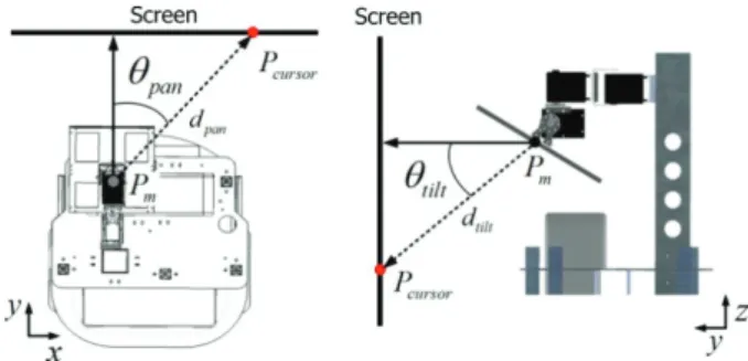
on the screen by extending the vector G as described in Figure 4. Then the UD projects images on the point Pcursor. By rotating the pan‐tilt mirror in the UD by pan and
tilt
as described in Figure 5, the inset image is displayed over the entire screen.
Figure 5. Rotating the mirror with pan and tilt
To calculate the point Pcursor, we need to find the intersection of a line and a screen (plane). The equation of the screen can be written as
N P P( cursor) 0 (1) where points P are on the screen with normal vector N and point Pcursor on the screen. The equation of the line can be written as
P G P (2) t 1 where points P are on the line passing through points
1 xhand,yhand, zhand
P and P2
xelbow,yelbow, zelbow
, Gis a vector in the direction of the line (G P P ), and t 1 2 is a scalar in the real number domain. If the inner product of two vectors G and N is zero, there is no solution.
Here, points Pcursor, P and 1 P2
should be represented by a coordinate system in the iSpace. The skeleton of the user extracted by the RGB‐Depth camera provides information about the position in the camera field of view. Since all cameras in the iSpace are calibrated, a coordinate transformation is not difficult. We can pre‐ compute the transformation by using four corresponding points [15].
3.2 Interactive Display Using Gestures
The gestures and the corresponding commands are predefined as described in Figure 6. To set a ROI, the user should raise the right hand high. Then the iSpace recognizes the relative height of the right hand, compared with the location of the right shoulder ‐ the iSpace then translates the gesture into Command 1. Other gestures mean different commands according to different applications.
Once the user’s ROI is set, the UD projects a visual marker, which is a white quadrangle, to determine the precise location of the overlap area which is a portion of an original image. For the marker detection, we use an image captured by a camera in the iSpace. The marker can be easily extracted by thresholding. After the closing operation, we can extract the four corners of the visual marker in the image using the Harris corner detection
method [16]. The four corners can be determined using the large eigenvalues of an autocorrelation matrix computed from image derivatives. The four corners represent the projected area covered by the UD. Figure 6. Command gestures However, the four corners found in the previous step are in the camera coordinate system. To extract the image for the UD from an original image, the coordinates of four corners are required to be transformed into the original image coordinate system. There are the relations of projective transform among a camera image, a screen, a projector image and an original image. Therefore, the four corners of the marker in the camera image are transformed by this relation [15]. Figure 7 shows all the relationships between each coordinate system.
Figure 7. Coordinate transform
In addition, the off‐axis projection by the UD does not guarantee the consistency in the shape of the overlap area. To display consistent rectangular images, we modify the original ROI to be inside of the overlap area as described in Figure 8. lw and lh indicate the size of the
final ROI.
Figure 8. Determination of a size of the small display
Figure 9. Multi‐resolution display
Overlap in the final ROI results in a double image or a blurred image. To solve this problem, we simply make a cut‐out in the ROI area in the original image so that only the image from the UD is displayed in the overlap area as in Figure 9. 4. Experiments 4.1 System Set up In our system, we have set up a vision‐based iSpace. The DINDs perform diverse functions such as human detection, robot detection, ROI detection, hand gesture recognition and so on. In our iSpace, we use in total nine camera DINDs (eight RGB cameras and one RGB‐Depth camera). Four RGB cameras were mounted at approximately 2m above the floor to cover the entire space.
Since this type of DIND is used for detecting humans and the UD, we call it a position module. Another four RGB cameras were installed on each wall at 1.6m above the floor. This type of DIND is called a face module. It is used for gaze estimation. In addition, it can be used for face tracking, face identification and facial expression recognition. An RGB‐Depth camera was installed on a wall at 1.8m above the floor. This RGB‐Depth camera is used for hand gesture recognition. Each of the camera DINDs can send and receive data packets including contents of processed information. The iSpace estimates the 3D positions of the user and the UD, recognizes the user’s gestures and controls the UD. The stationary projector is fixed at the same place. This is connected with a PC and used for a large display. In this work, we used OpenRTM‐ aist [17] for the system integration. 4.2 Results We conducted experiments to show the feasibility of the proposed system. In these experiments, the images were projected onto a flat surface, especially a wall. After determining the position in the iSpace where the user was pointing to, the UD projected a visual marker as shown in Figure 10. By rotating the pan‐tilt mirror in the UD, the UD could track the pointing position and give feedback. Figure 11 shows the results that the four corners of the visual marker extracted. By this approach, we could determine the precise location of the overlap area and easily calculate the homography for projecting an inset image. Figure 10. Tracking the position where the user is pointing to Figure 11. Four corners of visual marker: (a) input image, (b) extraction of a white quadrangle by thresholding, (c) results of corner detection
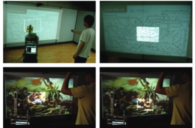
Figure 12 shows sample images of experimental results for the multi‐resolution display. As a result, the UD could produce a small display of better brightness and resolution in the ROI than the large display.
Figure 12. Sample images of the multi‐resolution display We considered two simple applications to demonstrate the feasibility of our interactive multi‐resolution display. One is a multi‐resolution map browsing. The users could move and zoom‐in/out of the map using gestures. The other is a subway guide. By recognizing gestures, the user could set his/her departure station, followed by his/her arrival station, and the UD could show the train schedule, quickest route, transfer points and fare information to the user. Results are shown in Figure 13 and Figure 14. Figure 13. Application scenario 1: multi‐resolution map browsing Figure 14. Application scenario 2: subway guide 5. Conclusions
In this paper, we proposed a novel interactive multi‐ resolution display system. The proposed system is based on a UD in an iSpace. As the iSpace can recognize the Region of Interest (ROI) from a user’s pointing gesture and the UD can project an inset image onto the surface where the user is pointing to, the user can focus on the ROI in high resolution and simultaneously be aware of the peripheral information in low resolution [7]. In the experiments, we have demonstrated its feasibility for interactive multi‐resolution display. Our system does not require that the user carry some form of apparatus. In addition, because natural and intuitive hand movements of the user are used, it is easy to interact with the system.
However, the current design of the proposed system is for a single user only. In the future, multiple UDs will be used for multiple users. Moreover, by using hand gestures, especially a finger pointing gesture, a more natural and intuitive interface will be implemented for human‐robot or human‐space interaction.
6. Acknowledgments
This work was supported by the Ministry of Knowledge Economy (MKE) of Korea, Korea Institute for Advancement of Technology (KIAT) and the Ministry of Culture, Sports and Tourism (MCST) of Korea through the Human Resource Training Project for Strategic Technology, and the Strategic Technology Development Program (Project No. 2008‐F‐033‐02). This work was also supported by KAKENHI (23500248).
7. References
[1] C. Pinhanez, “The Everywhere Displays Projector: A Device to Create Ubiquitous Graphical Interfaces.” In Proceedings of the 3rd international conference on Ubiquitous Computing, Atlanta, Georgia, USA, September, 2001.
[2] R. Raskar, J. van Baar, P. Beardsley, T. Willwacher, S. Rao and C. Forlines, “iLamps: Geometrically Aware and Self‐Configuring Projectors.” ACM Transactions on Graphics, 22(3) : 809‐818, 2003.
[3] R. Raskar, M. S. Brown, R. Yang, W.‐C. Chen, G. Welch, H. Towles, B. Seales and H. Fuchs, “Multi‐ Projector Displays Using Camera‐Based Registration.” In Proceedings of IEEE Visualization ‘99, San Francisco, CA, USA, October, 1999.
[4] P. Mistry and P. Maes, “SixthSense – A Wearable Gestural Interface.” In Proceedings of SIGGRAPH Asia 2009, Emerging Technologies, Yokohama, Japan, 2009.
[5] M. Ashdown and P. Robinson, “Escritoire: A Personal Projected Display,” IEEE Multimedia Magazine, 12(1):34‐42, 2005.
[6] T.‐T. Hu, Y.‐W. Chia, L.‐W. Chan, Y.‐P. Hung and J. Hsu, “i‐m‐Top: An interactive multi‐resolution tabletop system accommodating to multiresolution human vision.” In Proceedings of Third IEEE International Workshop on Tabletops and Interactive Surfaces Tabletop 2008, Amsterdam, The Netherlands, October, 2008.
[7] K.‐W. Chen, C.‐W. Lin, T.‐H. Chiu, M. Y.‐Y. Chen and Y.‐P. Hung, “Multi‐Resolution Design for Large‐ Scale and High‐Resolution Monitoring.” IEEE Transactions on Multimedia, 13(6):1256‐1268, 2011. [8] J. Park and M.‐H Kim, “Interactive Display of Image
Details using a Camera‐coupled Mobile Projector.” In Proceedings of The Twenty‐Third IEEE Conference on Computer Vision and Pattern Recognition Workshops, San Francisco, CA, USA, June, 2010. [9] P. Baudisch, N. Good and P. Stewart, “ Focus Plus
Context Screens: Combining Display Technology with Visualization Techniques.” In Proceedings of The 14th Annual ACM Symposium on User Interface Software and Technology, Orlando, FL, USA, November, 2001.
[10] J. Geisler, R. Eck, N. Rehfeld, E. Peinsipp‐Byma, C. Schütz and S. Geggus, “Fovea‐Tablett®:A New
Paradigm for the Interaction with Large Screens.” In Proceedings of the Symposium of Human Interface 2007, New York, NY, USA, June, 2007.
[11] J.‐H. Lee and H. Hashimoto, Intelligent Space ‐ concept and contents. Advanced Robotics, 16(3):265‐ 280, 2002
[12] J.‐H. Lee, “Human Centered Ubiquitous Display in Intelligent Space.” In Proceedings of the 33rd Annual Conference of the IEEE Industrial Electronics Society, Taipei, Taiwan, November, 2007
[13] J.‐E. Lee, J.‐H. Kim, S.‐J. Kim, Y.‐G. Kim, J.‐H. Lee and G.‐T. Park, Human and Robot Localization using Histogram of Oriented Gradient(HOG) Feature for an Active Information Display in Intelligent Space. Advanced Science Letters, 9 :99‐106, 2012 [14] OpenNI : openni.org [15] R. Hartley and A. Zisserman, Multiple View Geometry in Computer Vision, Cambridge University Press, New York, 2003, 2002 [16] C. Harris and M.. Stephens, ”A combined corner and edge detector.” In Proceedings of the Fourth Alvey Vision Conference, Manchester, UK, August, 1988 [17] OpenRTM‐aist : www.openrtm.org