8-4 / H.-M. Cho
• IMID 2009 DIGEST
Abstract
In order to improve discharge characteristics in AC PDP, we suggest FDFA (Facing Discharge Front plate Address Electrode) structure. By adopting both long facing discharge electrodes and address electrodes in front plate, the FDFA structure make it possible to gain a high luminance, low power consumption, and a high luminous efficiency.
1. Introduction
AC Plasma Display Panel (AC-PDP) with ITO structure is the most general flat panel display device for digital TVs. AC-PDP is rapidly growing in the market as large area displays all over the world. However, address discharge is unstable in ITO structure because the distance between sustain electrodes on the front plate and address electrode on the rear plate is relatively large. As a result, it is difficult to achieve both dynamic operating voltage margin and high luminous efficiency in ITO structure. So, Facing Discharge Front plate Address Electrode structure (hereafter, “FDFA”) is suggested. FDFA structure is expected to achieve high luminous efficiency and to achieve sufficient dynamic operating voltage margins using FDFA structure. In FDFA structure, distance between the sustain electrodes for scan and address electrodes is shorter than that of the ITO structure, as sustain electrodes and address electrodes are placed in the same front plate glass. It seems that barrier rib height and phosphors do not affect address voltages. [1],[2]
2. Experimental
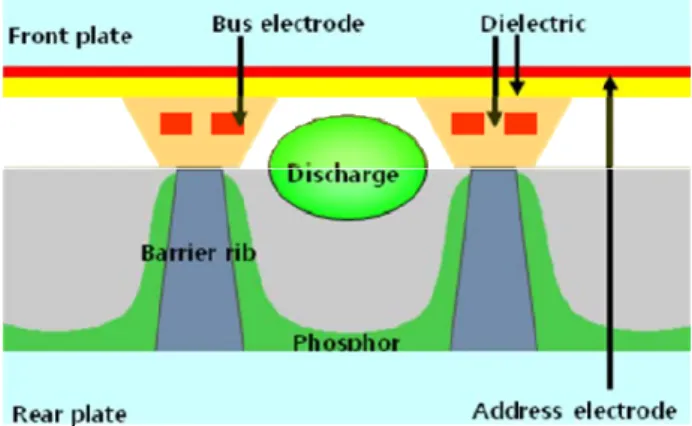
Fig.1. Shows schematic drawing of the FDFA structure. FDFA cell structure has closed-box shape dielectric layer on the front glass in order to reduce cross-talk and to stabilize discharge. Address electrodes are placed on the front glass plate and covered with the first dielectric layer. Sustain electrodes are located on the first dielectric and covered with the second dielectric layer. Barrier rib was formed and green phosphor was deposited on rear plate. The measurements were obtained under continuous sustaining with frequency 10 kHz and 25% duty square pulses.
Fig. 1. Schematic of the FDFA structure.
Characteristic of Facing Discharge Front plate Address
Electrode Structure in AC PDP
Hyun-Min Cho
1, Dong-Hwan Kim
1,
In Cheol Song
1,
Yun-Gi Kim
1,
Jung-Woo Ok
1,
Dong-Hyun Kim
1,
Hae June Lee
1, Ho-Jun Lee
1and Chung-Hoo Park
11Dept. of Electrical Engineering, Pusan National University,
san 30 Jangjeon-dong, Busan 609-735, South Korea
TEL:82-51-510-1544, e-mail: [email protected]
8-4 / H.-M. Cho
IMID 2009 DIGEST •
Fig. 2. Cell specification of the FDFA structure.
Fig. 2. shows cell specification of FDFA structure. Cell pitch of FDFA structure is 480 X 450µm due to the less plasma loss toward barrier ribs and the higher open ratio.[3] Delta type was designed for the luminous efficacy was considerably higher than that of the ITO structure.[5]
Cell pitch of the ITO structure is 300 X 676 µm which is the dimension of one cell in 42-inch PDP with XGA resolution. The ITO electrode gap of the ITO structure used as reference is 60 µm.
TABLE 1. Specification of the test panel
Table 1. shows the specification of the test panel. The thickness of the first dielectric layer is 30µm. In order to prevent breakdown of insulation on discharge, the thickness of the second dielectric layer is 35µm.
3. Results and discussion
Fig. 3. shows static voltage margin of the ITO and FDFA structures. FDFA structures have relatively higher firing voltage than that of ITO structure
because of their long discharge gap between electrodes. Fig. 4. shows luminance characteristic of the ITO and FDFA structures. The luminance of the FDFA structures is higher than that of ITO structure, and luminance is also higher with discharge gap size in FDFA structure.[4] The more the discharge gap is extended, the higher the luminance increment is obtained in The FDFA structure.
Fig. 3. Static voltage margin of the ITO and FDFA structure.
Fig. 4. Luminance characteristic of the ITO and FDFA structures.
Fig. 5. shows power consumption characteristic of the ITO and FDFA structures. Power consumption of the FDFA structures is lower than that of the ITO structure. Decrement ratio of the FDFA structure is lower, which is thought to be the smaller electrodes area than that of the ITO structure. The power consumption of the FDFA structure with 200 µm and 250 µm discharge gap is almost same at the same voltages
Working Gas : Xe (8%) + Ne Base, 400 Torr Front panel Rear panel Discharge
gap 200,250 µm Electrode Address Width 50 µm Bus Electrode Width 50 µm Whiteback Thickness 25 µm Dielectric
Thickness 65 µm Thickness Phosphor 25 µm MgO
Thickness 5000Å Rib Height 120µm
Vfmax Vfmin Vsmax Vsmin 160 180 200 220 240 260 280 300 320 340 V ol ta ge [V ] gap200 gap250 ITOgap60 180 200 220 240 260 280 300 320 340 200 300 400 500 600 700 800 900 1000
Lu
mi
na
nc
e [
cd
/m
2]
Voltage [V] gap200 gap250 ITOgap608-4 / H.-M. Cho
• IMID 2009 DIGEST
Fig.6. shows the luminous efficacy characteristics. The luminous efficiency of the FDFA structures with 250 um discharge gap is approximately 78% higher than that of the ITO structure. From this result, in spite of the long electrode gap, the FDFA structure shows a high luminous efficiency which is thought to be one of the advantages of facing electrode structure.
Fig. 5. Power Consumption characteristic of the ITO and FDFA structure.
Fig. 6. Luminous efficacy characteristic of the ITO and FDFA structure.
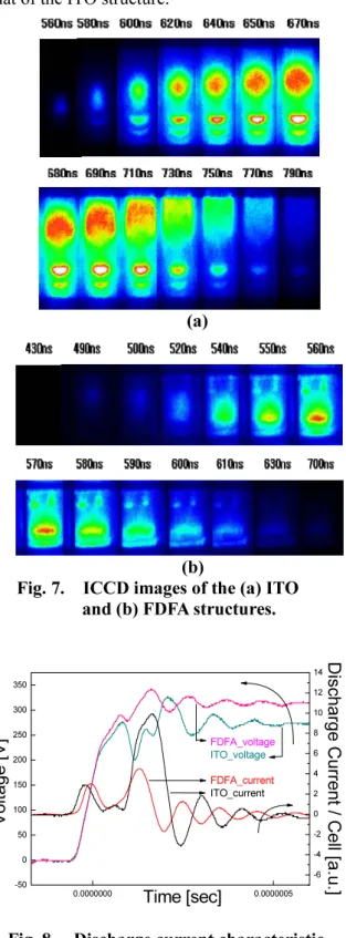
In order to compare with detailed distribution of discharge between the ITO and FDFA structures, Spatio-temporal distribution of IR emission from single cell discharge was taken by gate mode intensified charge coupled device (ICCD) camera. Fig.7. shows ICCD images of the (a) ITO and (b) FDFA structures (at gap 200 µm). A measured condition of the images such as ICCD gain was the same for both the ITO and FDFA structure. Discharge
start time of the FDFA structure faster about 60 ns than that of the ITO structure in spite of long electrode gap because discharge path of the FDFA structure is directly faced with sustain electrodes. However, Discharge duration time of the FDFA structure shorter than that of the ITO structure.
(a)
(b)
Fig. 7. ICCD images of the (a) ITO and (b) FDFA structures.
0.0000000 0.0000005 -50 0 50 100 150 200 250 300 350 -6 -4 -2 0 2 4 6 8 10 12 14 Disc ha rg e C urr en t / C ell [a .u .] V ol ta ge [V ] Time [sec] FDFA_voltage ITO_voltage FDFA_current ITO_current
Fig. 8. Discharge current characteristic of the ITO and FDFA structure.
180 200 220 240 260 280 300 320 340 0.1 0.2 0.3 0.4 0.5 0.6 0.7 0.8 0.9
Po
we
r C
on
su
mp
tio
n [
W
]
Voltage [V] gap200 gap250 ITOgap60 180 200 220 240 260 280 300 320 340 1.5 2.0 2.5 3.0 3.5 4.0 4.5 5.0Lu
mi
no
us
E
ffic
ac
y [
lm
/W
]
Voltage [V] gap200 gap250 ITOgap608-4 / H.-M. Cho
IMID 2009 DIGEST • Discharge current characteristic of the ITO and FDFA
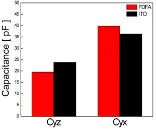
structure is shown in fig. 8. Discharge current of the FDFA structure is lower and faster than that of the ITO structure. The characteristics of discharge current waveform and discharge evolution in the fig.7 were well matched. Fig. 9. shows capacitance characteristic of the ITO and FDFA structure. The capacitance between sustain electrodes is Cyz and between sustain electrodes for scan and address electrodes is Cyx. Cyz of the FDFA structure lower than that of the ITO structure. Because electrode distance of the FDFA structure is longer than that of the ITO structure. In addition, electrode area of the FDFA structure is smaller than that of the ITO structure. Cyx of the FDFA structure is larger than that of the ITO structure because the distance between sustain electrodes for scan and address electrodes is shorter than that of the ITO structure.
Fig. 9. Capacitance characteristic of the ITO and FDFA structure.
4. Summary
In order to improve the luminous efficacy in AC PDP, the FDFA structure was suggested. As a result, the FDFA structure showed that higher luminance, luminous efficacy, wider voltage margin, lower power consumption than that of the ITO structure. Through analyzing discharge current waveform and ICCD images, the FDFA structure which is compared with the ITO structure at the same voltage can be operated at the low electric field. In addition, the FDFA structure has fast discharge time due to the facing discharge structure. From this result, the FDFA structure has enhanced performance.
5. References
1. D.W. Kim, J.W. Ok, J.H. Jang, J.H. Lim, D.H. Kim, H.J. Lee and C.H. Park Japan-Korea Joint Symposium on Electrical Discharge and High Voltage Engineering 16P-27 (2007).
2. M. Yoshinari, Y. Shintani, T. Ishibashi, Y. Okumura, T. Komaki Journal of the SID 14/8 (2006).
3. T.J. Kim, C.K. Yoon, and K.W. Whang IEEE TRANSACTIONS ON PLASMA SCIENCE, VOL. 34, NO.3, JUNE 2006.
4. J.W. Ok, D.W. Kim, S.Y. Cho, H.-J. Lee, H.J. Lee, and C.H. Park SID 07 DIGEST P-88 (2007).
5. C.K. Yoon, J.H. Seo, W.J. Chung, K.C. Choi, and K.W. Whang in Proc. IDW, p.167 (2000)
0 5 10 15 20 25 30 35 40 45 50 Cyz C ap ac ita nc e [ p F ] FDFA ITO Cyx