ICCAS2005 June 2-5, KINTEX, Gyeonggi-Do, Korea
1. INTRODUCTION
The mobile robots like snake robots are playing a critical role in many applications. Researchers have hopes of creating robots that can detect mines, explore Mars, or search for people trapped beneath an earthquake-damaged building. Serpentine mechanisms offer unique capabilities on earth to applications such as bridge inspection, search and rescue operations. Snakes motion capabilities different from many other animals. It can use its body as legs, arms or fingers [1, 2]. This unique feature of snakes offer snake robots as a useful tool in many real applications like inspection of broken buildings and pipes. It can also be used in places where human movement is restricted .The wave motion of snakes can push the obstacles and create its own way for further movement. Unlike many mechanical locomotives, movement of snake robots is not straight; it can turn to a side where there is a way to move further. The mechanical based snake robots are complex to design because of their many degrees of freedom [3, 4]. This requires complex and careful motion planning. Although the many of degrees of freedom of serpentine robots supply great functionality, they also supply a challenging research problem of how to coordinate all of the actuators in the robot to yield purposeful motion[5] .To implement this wave like motion of snakes, we have developed a snake robot prototype with LEGO Mindstrorm toolkit[6]. Our main approach here is to control and synchronize the snake movement effectively using concurrent programming model. Many microcontroller and mechanical based robots lacks the flexibility to control the snake movements. The main obstacle in such approaches is co-coordinating between individual units (Figure.1) of snake robot and flexibility in generating robot locomotion; also such methods are more expensive and time consuming.
2. RELATED WORKS
The snake robot is an active area of research in recent years. To generate flexible movements, some robots make use of rubber-joints. This is to bend in arbitrary directions and to make the snake robot’s body very flexible, as in GMD snake [3].There were many other robots developed over the years. In case of its locomotion, many of these robots lacks the features of program controlled concurrent model to generate wave-like motion. Some robots were designed to generate sine wave motion using microcontroller based programs [8]. Robots were developed to move on the surface of water or land, but use a system of coupled oscillators to generate wave like
motion [9]. The commonly used locomotion control methods are trajectory based methods and heuristic methods. Many of such implementations use a simulation based methods to control the robot movement.
3. DESIGN REQUIREMENTS
Snakes move by pushing their body against environment. To achieve this, snake robot sections (Figure.1), must generate serpentine locomotion or lateral undulation. Lateral undulation is a sequence of left-right wave movements to accomplish real snake’s locomotion. Generating sine wave locomotion is the basic issue in designing snake robot. Also it is important to move the robot in left, right, circular, rectilinear, concertina, serpentine and side winding [10] based on robot user requirements. The second issue is about co-coordinating between two adjacent sections of the robot. This is important to generate the serpentine locomotion. The third issue is about robot performance in case of robot section or unit (Figure.1) failure. In case of any robot section or unit failure, the robot may break into pieces and may lead to great loss in case of critical applications. In such cases the robot must continue to operate along with its broken sections rather than total robot failure. Adding or removing a robot section or unit from the robot and retaining the same robot behavior are also our design consideration. The mechanical design of the robot is also equally important to support the above mentioned features.
4. PROPOSED ROBOT ARCHITECTURE
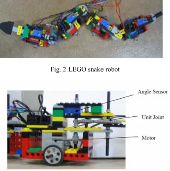
4.1 Hardware ConfigurationThe physical prototyping of snake robot developed using LEGO toolkit as shown in figure 2. In the present model, we have used 4 motors as actuators and 4 angle sensors as sensors. The angle sensors are used to co-ordinate the sequence of sine wave movements in a particular direction and in a particular path along with motors, together form a unit in our robot. Each motors work as actuator to drive a unit of snake robot. Here a unit is a primitive individual element of robot. Many units together make a section as shown in the figure 1. In general a snake may have N sections (1≤k≤N) and each section may have M units (1≤p≤M).
The total number of units = N×M =Total number of motors needed.
In the present design there are only two units (motors) per section. Altogether there are 4 units with one motor/unit. All
Multi-Thread based Synchronization of Locomotion Control in Snake Robots
Laxmisha Rai * and Soon Ju Kang **
School of Electrical Engineering and Computer Science, Kyungpook National University (KNU), Korea *(Tel : +82-53-940-8664; E-mail: [email protected])
** (Tel : +82-53-950-6604; E-mail: [email protected])
Abstract:
In this paper, we present an approach to control the locomotion of snake robot with concurrent programming model
constructed using threads and semaphores. The multi-thread based concurrent programming model adds the flexibility to design and synchronize the movement of snake robots as compared with microcontroller and mechanical based approaches. We have designed a physical snake robot using LEGO sensors and actuator blocks and the wave motion of the snake robot is generated by multi-thread based concurrent programming under RT-Linux. The different robot movements in a desired direction along with different types of snake movements are achieved using angle sensors.Keywords: Mobile Robot, Thread, Synchronization, Concurrent Programming, Serpentine
ICCAS2005 June 2-5, KINTEX, Gyeonggi-Do, Korea
motors run at equal speed [3]. The mechanical structure of the
robot is equally important to realize the wave like motion of the robot. The selection of number of units in a particular section and number of sections in the robot depends on the robot designer’s choice. The present robot moves by pushing its body against the surface. The wheels connected to the each unit of the robot support this locomotion; this naturally makes the last unit (Nth) as head and first as tail. Although, in the present model all units acts independently, the head has no special function as in many robots, where the head defines the path. The figure 2 shows the photographic view of the robot.
Fig. 1 Schematic diagram to explain robot sections and units.
Fig. 2 LEGO snake robot
Fig. 3 View of snake robot.
A hardware interface is already developed in our lab to support many sensors and actuators of LEGO kit. This mainly includes touch sensors, light sensors, angle sensors, motors etc. The API (Application Programming Interface) which is developed in our lab supports many fundamental features to use these sensors and actuators in the present model. [7].A typical embedded computer system with LEGO sensors and actuator interfacing can be shown as shown in figure 4. The PC104 is an embedded computer standard and commonly used with LEGO systems. The PCI 104 is suitable for development of autonomous embedded robot control applications.
Fig. 4 An embedded computer system with LEGO sensors and actuators.
4.2 Software Architecture
The present model is implemented in RT-Linux based dual kernel environment as shown in figure 5. This architecture support both real time and non-real time tasks execution. The FIFO and shared memories are IPC (Inter-Process Communication) modules to support communication between real-time and non-real-time tasks. Also, GUI based user interface can be provided to control the robot movements.
Fig. 5 RT-Linux Dual Kernel Architecture.
To emulate the snake behavior, threads and semaphores are used. The program uses maximum N (1≤k≤N) number of threads. The wave movement of the snake is realized by understanding the relationship between two adjacent sections, k and k+1 as shown in figure 1.Threads and semaphores were used to synchronize this relationship between two adjacent sections. In the present approach, N numbers of threads are required in a robot with N sections. The pseudo code of the program is shown below:
main ( ){ initialize_motors_sensors (); initial__calibration (); initialize_semaphores (); thread_section_1 (); …. …. thread_section_N(); semaphore_destroy (); end_ calibration(); }
948
ICCAS2005 June 2-5, KINTEX, Gyeonggi-Do, Korea
The Figure.6 illustrates the robot unit movements in particular module of the program. This is the sequence of motor/unit movements when the entire code is executed at least once. In the initial calibration phase, the all motors turn in a particular direction with an angle value of Φ. As shown in the figure, when the motor 1 is running in right direction motor 2 is running in left direction and vice-versa. This is same for motors 3 and 4.
In the thread section phase, the motors run continuously with an angle of 2Φ inside the while loop and synchronization between the units of two threads is achieved using semaphores as shown in the above code. In this case, thread section modules executes continuously. A counter may be provided to run the motor for a particular period of time. The end calibration section is needed to bring back the robot to its original position. The major difference between calibration sections to the thread sections is the angle senor value. In case of calibration sections the robot unit is turns left or right by an angle of Φ, where as in case thread section , by 2Φ. In this robot the for every angle sensor value (AS Value) of 5 the robot turns with 22.5 degrees.
Fig. 6 Figure to understand the sequence of robot unit movements in different modules of the program.
In the above code, the SPEED is the speed of the motors in each unit of snake maintained at a constant level. The speed can be changed dynamically during the movement of the robot. The L(Left) and R(Right) indicate the direction of movements. The statement set_rotation_handler (angle_sensor(S (k+1, p)), ASValue); sets angle sensor of unit p of section k+1 with required angle Φ (with equivalent AS Value) to generate sine-wave. The statement run_motor(S (k+1, p), L, SPEED); turns the unit p in section k+1 of snake robot in left direction with speed value of SPEED. However it is important that mass is homogeneously distributed along the length of the snake robot and also the body retains symmetry among its contacts between two sections [8].
5. EXPERIMENTAL EVALUATION
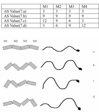
5.1 Testing and ResultsThe present robot used wheels for its movement. And we have tested the movement of robot for sine- wave like motion. The robot is tested for to exhibit real snake behavior. The robot generated the different kinds of snake movements as shown in figure 7. The different movements (a, b, c, d) are generated with different angle sensor values. The table.1 illustrates various robot movements generated by setting different angle sensor values to different motors (M1 to M4)
Table 1. Angle sensor values for different robot movements. M1 M2 M3 M4 AS Value(7.a) 3 3 3 3 AS Value(7.b) 9 9 9 9 AS Value(7.c) 12 9 6 3 AS Value(7.d) 3 6 9 12
Fig. 7 Different types of snake locomotion generated with different angle sensor values
(a) Rectilinear (b) Serpentine (c) and (d) Concertina 5.2 Advantages and Limitations
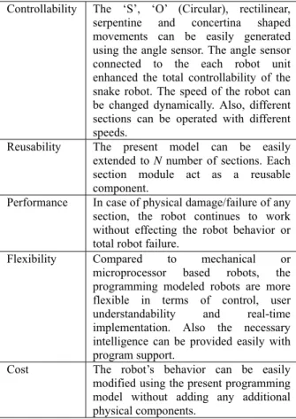
The model proposed in this paper has numerous advantages as shown in table 2. The basic advantages are controllability, reusability, better performance, flexibility and cost effectiveness. As compared with mechanical or microprocessor based robots the proposed model is more flexible and controllable. The number of threads required is directly proportional to the number sections in the robot, leads //Thread for Section k+1
start_section_k+1() {
while (1){
sem_wait(&sem_k);
set_rotation_handler (angle_sensor(S (k+1, p)), 2*ASValue) run_motor(S (k+1, p), R, SPEED);
set_rotation_handler (angle_sensor(S (k+1, p+1)), 2*ASvalue) run_motor(S (k+1, p+1), L, SPEED);
sem_post(&sem_k+1); }
thread_exit(NULL); }
//Thread for Section_k start_section_k () { while (1) {
sem_wait(&sem_k+1);
set_rotation_handler (angle_sensor(S (k, p)), 2*ASValue) run_motor(S (k, p), R, SPEED); set_rotation_handler(angle_sensor(S (k, p+1)), 2*ASValue) run_motor(S (k, p+1), L, SPEED); sem_post(&semk); } thread_exit(NULL); }
949
ICCAS2005 June 2-5, KINTEX, Gyeonggi-Do, Korea
to many threads and semaphores. This may cause some delay
of execution between robot sections.
Table 2. Advantages of the proposed model. Controllability The ‘S’, ‘O’ (Circular), rectilinear,
serpentine and concertina shaped movements can be easily generated using the angle sensor. The angle sensor connected to the each robot unit enhanced the total controllability of the snake robot. The speed of the robot can be changed dynamically. Also, different sections can be operated with different speeds.
Reusability The present model can be easily extended to N number of sections. Each section module act as a reusable component.
Performance In case of physical damage/failure of any section, the robot continues to work without effecting the robot behavior or total robot failure.
Flexibility Compared to mechanical or microprocessor based robots, the programming modeled robots are more flexible in terms of control, user understandability and real-time implementation. Also the necessary intelligence can be provided easily with program support.
Cost The robot’s behavior can be easily modified using the present programming model without adding any additional physical components.
6. CONCLUSION
Many snake robots were already developed with defined head and tail. Usually head defines the path for its body. This method has some disadvantages. If the robot's head fails during its operation, then the rest of the body also stops operation. The present model overcomes these limitations. Each unit or sections can be designed to operate independently. We have implemented angle sensors and motors to realize the behavior of the snake. Our purpose is to create a model which can be used in many real-life applications and to realize multithreaded concurrent programming. The forces generated during its locomotion are of little importance and it is neglected here. In this paper we shown the design of a LEGO based snake robot and its programming implementation. The wave-like movement of snake is effectively generated by using programming constructs like semaphores and threads with effective use of angle sensors. Also, the present programming model can be applied to robots where complex concurrent locomotion is an absolute requirement.
ACKNOWLEDGEMENTS
This work was supported by grant No. R01-2003-000-10252-0 from the Basic Research Program of Korea Science and Engineering Foundation.
REFERENCES
[1] Linda Dailey Paulson: Biomimetic Robots. IEEE Computer 37(9): 48-53 (2004) September 004,
Volume 37, Number 9.
[2] Choset and W. Henning, A Follow-the-Leader Approach to Serpentine Robot Motion lanning, ASCE Journal of Aerospace Engineering, 1999
[3] Paap, Karl L, Christaller, Thomas; Kirchner, Frank, A Robot Snake to Inspect Broken Buildings,In proceedings of the 2000 IEEE/RSJ International Conference on Intelligent Robots and Systems (IROS 2000), (2000), p. 2079 – 2082
[4] Shigeo Hirose and Edwardo F. Fukushima, Snakes and Strings: New Robotic Components for Rescue Operations, Tokyo Institute of Technology, 2-12-1 Ookayama Meguro-ku,JAPAN,
www.iser02.unisa.it/papers/k3.pdf
[5] Kevin J. Dowling, Limbless Locomotion: Learning to Crawl with a Snake Robot, Ph.d Theses, The Robotics Institute, Carnegie Mellon University 5000 Forbes Avenue,Pittsburgh,PA-15213,
www.solarbotics.net/library/pdflib/pdf/limbless_locomot ion.pdf
[6] LEGO Home Page www.legomindstorms.com
[7] Gi Hoon Jung, Do Hoon Kim, Sung Ho Park, Ok Gu Kim , Soon Ju Kang , Experimental Software Engineering Course for Training Embedded Real-Time Systems, SERP ’02 , International Conference Proceedings, p.410-416
[8] Mark W. Sherman , Sine-Wave Locomotion in a Robotic Snake Model Form and Programming,
http://arctangent.8k.com/snake/snakerobot.pdf
[9] Alessandro Crespi, Andre Baderscher, Andre Guignard and Auke JanIjspeert, AmphiBotI: An amphibious snake like robot,
http://birg2.epfl.ch/brig_papers/ras_preprint2004.pdf
[10] Tamara Knutsen, Designing an underwater eel-like robot and developing anquilliform Locomotion Control Harvard University,
www.ee.upenn.edu/~sunfest/pastProjects/Papers00/Knut senTamara.pdf