1. INTRODUCTION
Today’s car industry has made a great progress for last ten years, especially in the security for the people in cars, the car reliability,and the convenient functions for drivers. And this is largely indebted to the introduction of Electrics/Electronics and Control Engineering to vehicular industry. Nowadays, engines or chassis control without electronics and control could not be imagined. Car body control, however, has not been fully developed until now. Actually, the car body is controlled by set of complicated wiring harness(W/H) and junction box(J/B) which feed signals and power to terminal actuators such as lamps, relays, motors,and buzzers or chimes. But more functions and hence more actuators need more W/H’s weight and complication, which, therefore, causes the system less reliable. In answer to this problem, the CAN(Controller Area Network) protocol based approach has been developed since 1990s by some major car components suppliers, aiming at replacing actual W/H and J/B by CAN plus ISU(Intelligent Switch Unit) in near future [1, 2]. The CAN protocol, as one kind of field-bus communication, is very efficient for hard real-time distributed control,such as car body control, thanks to its rapid global response time and data arbitration ability through the identifiers.
This paper reports a developing procedure of the CAN-based real-time simulator for car body control. The simulator consists of 2 control boards for 5V signal and 12V action control, which are separate but connected each other by CAN lines, 1 power motor for washing windshield, 1 door lock motor, and 6 blink lamps for turning directions. In section 2, some characteristics of CAN protocol are briefly described in view of car applications. In sections 2 and 3, the implementation procedure is presented in sequence of its hardware architecture, control algorithm, and software architecture. And finally, section 5 gives some experimental results.
2. CHARATERISTICS OF CAN PROTOCOL
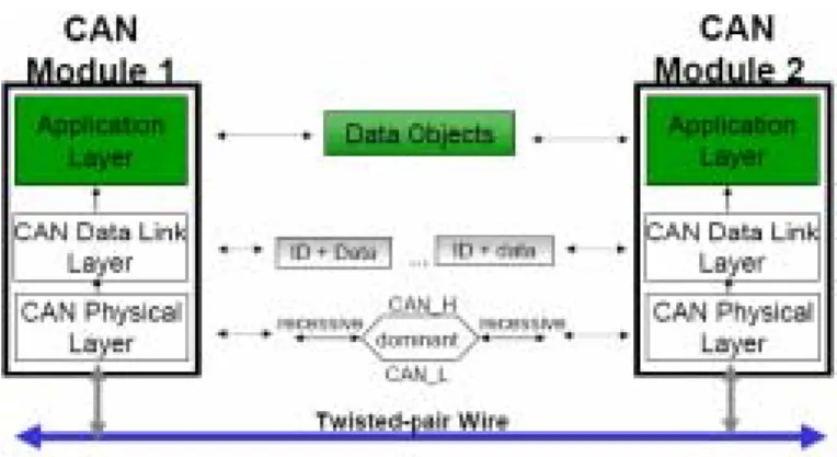
Bosch and Intel originally designed the CAN for the use in automobiles, jointly, mainly for the reliable and low-cost field-bus communication. And nowadays, low-cost MPUs with CAN controller interfaces are available, making CAN a mainstream network technology by virtue of its massive adoption by automakers worldwide. CAN defines the lowest 2 layers of the ISO/OSI standard, namely, the physical layer(PL) and the data link layer(DLL), for which the CSMA/NBA(Carrier Sense Multiple Access with Non-destructive Bitwise Arbitration) protocol is generally adopted [3, 4]. A general CAN system configuration is in Fig. 1, where CAN modules, depicted in Fig. 2.,are implemented.Fig. 1 General CAN system configuration.
CAN is not a conventional source-to-destination structure but a master-to-master one where every node has its own identifying address through the identifier bits of a data frame [5].
Development of a CAN-based Real-time Simulator for Car Body Control
Ki-Ho Kang*, and Sang Man Seong**
* School of Mechatronics, Korea University of Technology & Education, Cheonan, Korea (Tel : +82-41-560-1316; E-mail: [email protected])
** School of Mechatronics, Korea University of Technology & Education, Cheonan, Korea (Tel : +82-41-560-1313; E-mail: [email protected])
Abstract:
This paper presents adeveloping procedure of the CAN-based real-time simulator for car body control, aiming at replacing the actual W/H (Wiring Harness) and J/B(Junction Box) couple eventually. The CAN protocol, as one kind of field-bus communication, defines the lowest 2 layers of the ISO/OSI standard, namely, the physical layer(PL) and the data link layer(DLL), for which the CSMA/NBA protocol is generally adopted. For CPU, two PIC18Fxx8x’s are used because of their built-in integration of CAN controller, large internal FLASH memory (48K or 64K), and their costs. To control J/B’s and actuators, 2 controller boards are separately implemented, between which CAN lines communicate through CAN transceivers MCP255. A power motor for washing windshield, 1 door lock motor, and 6 blink lamps are chosen for actuators of the simulator for the first stage. For the software architecture, a polling method is used for the fast global response time despite its slow individual response time. To improve the individual response time and to escape from some eventual trapped-function loops, High/Low ports of the CPU are simply used, which increases the stability of the actuator modules. The experimental test shows generally satisfactory results in normal transmitting / receiving function and message trace function. This simulator based on CAN shows a promising usefulness of lighter, more reliable and intelligent distributed body control approach than the conventional W/H and J/B couple. Another advantage of this approach lies in the distributed control itself,which gives better performance in hard real-time computing than centralized one, and in the ability of integrating different modules through CAN.Fig. 2 CAN module architecture.
And the identifier has a priority for the data frame, which prevents eventual 2 data frames from colliding each other on the bus by selecting the preferred frame to transmit. Some more detailed characteristics are described as follows: 2.1 Message Frame
Message is transmitted through message frame with 2 types, the standard frame(CAN 2.0A) and the extended one(CAN 2.0B). CAN 2.0A has 7 fields for arbitration including 11-bit identifier, control, data, CRC, ACK, and EOF. CAN 2.0B is the same with CAN 2.0A except for arbitration field, where CAN 2.0B has 29 bits while CAN 2.0A 12 bits. The standard frame(CAN 2.0A) is detailed in Fig. 3.
Fig. 3 CAN 2.0A message frame. 2.2 Bit Timing
The arbitration needs that the maximum propagation time of the signal on the bus be much smaller than the duration of a bit, in other words “bit time”, because every node must be capable of reacting during the bit time. As a result, every CAN controller has a Bit Timing Register for regulating the bit time and hence the transmitting/receiving bit rate by changing data of the register [6].
3. HARDWARE ARCHITECTURE
3.1 Main controller partsA power motor for windshield washing, 4 door lock motors and 6 direction-turning blink lamps are chosen for actuator modules of the simulator for this first stage. So the hardware architecture consists of 2 control system boards for the purpose of 5V signal control and 12V action control, between which CAN lines communicate through CAN transceivers MCP255 of Microchip. Each control system board has main controller part and interface circuit part. For main controller part, two different PIC18Fxx8x’s are used because of their built-in integration of CAN controller, large internal FLASH
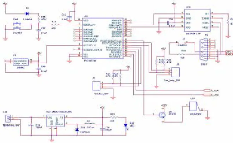
memory (48K or 64K) and their costs. This last point should not be neglected in automobile industry. The interface circuit part consists of power transistor(in fact, Darlington pair)-based circuit for driving motors (12V level action) and relays for turning on/off blink lamps (5V level action). Following figures (Fig. 4 and Fig. 5) show the schematics for the 2 main controller parts based on PIC18F248 and PIC18F6680, respectively.
Fig. 4 Main controller part schematic based on PIC18F248.
Fig. 5 Main controller part schematic based on PIC18F6680.
3.2 Interface circuits to actuator modules
In Fig. 6 and Fig. 7, two interface circuit schematics for 4 door lock motors, 1 power windshield motor, and 6 blink lamps are shown. The I/O ports are designed bitwise to control the switch/outputs flexibly through control part at each node. This flexibility comes from the bitwise control that minimizes the needed cable length and node number and that makes easy implementation and addition of supplementary functions.
Fig. 6 Interface circuit schematic for door lock and power window motors.
Fig. 7 Interface circuit schematic for door blink lamps.
3.3 Implemented control system boards
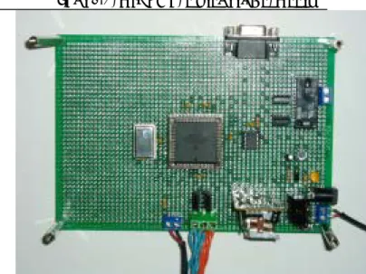
The implemented controller plus interface circuit system boards are shown in Fig. 8 and Fig. 9.
Fig. 8 Implemented control system board ( PIC18F248).
Fig. 9 Implemented control system board ( PIC18F6680).
4. CONTROL SOFTWARE IMPLEMENTATION
4.1 Program structureIf the control system is activated, every I/O is initialized. Then,when data are received by polling, independent I/O or data transmission requests occur. And the actuators are active under satisfied conditions, where every node transmits/receives message through its own identifying address and transmits identifier included messages. Fig.10 describes this process as a flowchart [7].
And the implementation procedure can be explained in more detail as following steps:
4.1.1 ID declaration
ID (Identifying address) declaration process is defined as follows.
4.1.2 Structures of transmit and receive functions Receive confirming is executed by checking set of 2 Rx buffer registers and CLEAR signal. Receive function returns ID, Data, DLC, Stat and True/False for the case of Rx buffer’s full/empty state. Transmit function verifies Set/Clear value in Tx buffer register and if Clear, starts transmission with its parameters such as ID, Data, DLC, frame type, ID extension or not and RTR. The return value is True/False for transmit success/failure.
4.2 Software implementation
For software implementation, CAN driving method should be defined firstly. Polling, interrupt or polling plus interrupt are possible with its own advantage and drawback. Polling method is used for the rapid global response time despite its slow individual response time. To improve the individual response time and to escape from some eventual trapped-function loops, High/Low ports of the CPU are simply used, which increases the stability of the actuator modules.
Using polling driving method, the receiving confirm function, can_rx(), in main() function is as in the following code, where the function can_get_message() delivers received message and True/False state. When True, parameters like ID, Data, received DLC, and receive states are delivered too :
And the transmitting confirm function, can_tx(), is as follows, where can_tx() function verifies transmission-ready state, and transmission or not, by executing AND operation between the switch input state and the actual key value. The function can_put_message() delivers parameters such as ID, Dta, DLC when all these conditions are satisfied.
5. EXPERIMENTAL RESULTS
5.1 Transmission and receiving verificationIn Fig. 11, the Tx/Rx signals are captured through an oscilloscope, which shows reliable communication ability in all cases. The CAN cable was 10m long.
Fig. 11 Tx/Rx for 1/2 matched signals. (A & B : magnified signals of 1 & 2)
5.2 Message trace test
Microchip’s third vendor ‘Diversified Engineering’ company offers a monitoring/debugging tool for Microchip’s PIC 18XX series, called ‘CAN Manager’ [8]. This tool gives some message trace function by which the developed simulator’s tracing capability was verified. Fig. 12 gives a verified result which is monitored on CAN Manager’s window. The test system has 2 nodes(master to slave) and 2 other input sources like voltage regulator and temperature input which varies continuously. So the data part corresponds to 6 hexadecimal part such as 00 00 00, where last 4 digits are reserved for normally received message generated by pushing the button 0x0f 0f.
Fig. 12 Traced message after 3 times pushing the transmitting button of the CAN Manger.
6. CONCLUSION
The experimental test shows generally satisfactory results in normal transmitting / receiving function and fundamental trace function. Further research is needed for more sophisticated functions such as self-diagnosis in case of J/B’s malfunction or failure, interrupt mode occurrence, and just-in operation for emergent situations. However, this simulator based on CAN shows a feasibility of full & serious developing of this approach because it is a potentially lighter, more reliable, and intelligent distributed body control approach than the conventional W/H plus J/B couple. Another advantage of this approach lies in the distributed control itself, which gives better performance in hard real-time computing than centralized one, and in the ability of integrating different modules through CAN.
ACKNOWLEDGMENTS
The authors gratefully acknowledge the partial financial contribution of Packard Korea Inc. & Korea Administration for Small & Medium Enterprises.
REFERENCES
[1] SAE, “Surface Vehicle Recommended Practice –High-speed CAN for Vehicle Application,” SAE Report, J2284-3, 2002.
[2] ISO, “Road Vehicles-Interchange of Digital Information –Controller Area Network(CAN) for high-speed communication,” ISO Directive, 11898, 1995.
[3] Robert Bosch GmbH, “CAN Specification,” Bosch
Report, Ver. 2, 1991.
[4] O. Pfeiffer, A. Ayre, and Ch. Keydel, Embedded
Networking with CAN and CANopen, RTC Books, San
Clemente, 2003.
[5] K. Etschberger, Controller Area Network: An
Introduction, TechOnLine, http://www.techonline.
com/community/ related_content/22590, Apr. 7, 2003 [6] K.W. Tindell, H. Hansson, and A.J. Wellings, Analyzing
Real-Time Communications: Controller Area Network (CAN), Proc. 15th Real Time Systems Symposium,
pp.259-263, IEEE Computer Society Press, 1994. [7] Jon Chidlow et al., “Harnessing the potential of
multi-master wiring systems, Multiplexing and Fiber optics,” SAE Report, 940366, 1994.
[8] Diversified Engineering., CAN Network Developing /
Training Modules–Instruction Manuals, Diversified