ICCAS2005 June 2-5, KINTEX, Gyeonggi-Do, Korea
1. INTRODUCTION
Recently, electronic instruments are being miniaturized and being high frequency. The IC and LSI have high density in its functions and TR gates. Therefore the density of generating heat of electronic instruments is swing upward rapidly. In order words, because the density of generating heat of electronic instruments is increasing, the internal temperature of electronic instruments is rising steadily. The temperature rise of the electronic instruments gives a big effect to the electronic component, which composes the product in its reliability and life, because the reliability and life of the electronic component are connected directly to the reliability of the electronic instruments. The semiconductor parts like as IC, which accomplish the main stream of the electronic instruments, are the representative heat generation parts because of its complicated function and high density. Consequently guaranteeing electronic component reliability and life of electronic parts like as IC is an important start point in securing the reliability and life of the electronic instrument product which electronic parts use.
There are many factors, which affect heat dissipation efficiency. The heat dissipation efficiency follows in the environment where the electronic instrument products are used. In case of the products are used in low temperature environment, it will be in a better position in the heat dissipation efficiency than those are used in high temperature environment. The heat dissipation efficiency is good when the bulk of the electronic instrument product is large, because of
its broad heat dissipation area. And if cool air can ventilate the electronic instrument product, the internal temperature of the product is low. These factors of environment, bulk of products, ventilation structure and etc make complicate analyzing reliability and life of the electronic manufactures. Therefore it is very difficult to define reliability and life of the electronic manufactures.
An electronic instrument product are composed of printed circuit board (PCB), integrated circuit (IC), resistance, capacitor, heat sink, heating pan, case and etc. It is defined as a thermal resistance, which interrupts for some parts to dissipate its heat to another medium. Because the parts like as resistance, capacitor and IC are arrayed on the printed circuit board (PCB), there are superposed thermal resistance. Therefore the total thermal resistance is variable. Consequently it cannot have same thermal model for each electronic instrument products.
This paper proposes one equivalent model for various electronic instrument products to analysis reliability and life of its parts like as IC.
2. THERMAL RESISTANCE NETWORK
In trend of electronic instruments technology, the size of device is going down sizing with high speed, high density and high power dissipation. The heat from the high power dissipation causes the delay for semiconductor signal timing. In the semiconductor parts, which have low timing margin, the heat makes an error in semiconductor function. Table 1 showsA study of guaranteeing reliability for IC of electronic instruments according
temperature
Geon Yoon*, Yong Oon Park**, and Soon Chang Kwon***
* Advanced Platform Lab, Automation R&D Center, LS Industrial Systems. Co., Ltd. Korea (Tel : +82-31-450-7585; E-mail: [email protected])
**Advanced Platform Lab, Automation R&D Center, LS Industrial Systems. Co., Ltd. Korea (Tel : +82-31-450-7627; E-mail: [email protected])
*** Advanced Platform Lab, Automation R&D Center, LS Industrial Systems. Co., Ltd. Korea (Tel : +82-31-450-7532; E-mail: [email protected])
Abstract: This paper discusses heat problem of IC, which composes the electronic instruments, to guarantee reliability of
electronic instruments. And also proposes the unified equivalent model for various electronic instrument products to guarantee reliability and life of its parts. Because electronic instruments are down sizing and operated with high frequency, the internal temperature of electronic instruments is rising steadily. The internal temperature of the electronic instruments gives a big effect to electronic instrument’s reliability and life. The semiconductor parts are the representative heat generation parts because of its complicated function, high frequency and high density. Consequently, guaranteeing reliability and life of electronic semiconductor is the important start point in securing the reliability and life of the electronic instrument product. Unfortunately, there are many factors, which affect heat dissipation efficiency. The heat dissipation efficiency follows the environment where the electronic instrument products are used. Therefore it is very difficult to define reliability and life of the electronic manufactures. Electronic instrument products are composed of printed circuit board (PCB), integrated circuit (IC), resistance, and capacitor and so on. And there are superposed thermal resistances, because the parts are arrayed on the printed circuit board (PCB), Therefore the total thermal resistance is variable. Consequently it cannot have same thermal model for each electronic instrument products. In the next part, we propose the unified equivalent model for various electronic instruments. And using the proposed equivalent model proofs the method for analysis reliability of electronic parts.
Keywords: Thermal Resistance, Junction Temperature
ICCAS2005 June 2-5, KINTEX, Gyeonggi-Do, Korea
the trend of Intel CPU processors.
Table 1 Comparison between Intel CPUs
CPU Core Name Prescott Northwood Operating Clock 3.6Ghz 3.2Ghz
Making progress 90nm 130nm
TR density 1 2 5million gate 5 5million gate
Power dissipation 103W 82W
The Prescott CPU processor is latest Intel CPU processor for the personal computer (PC). The power dissipation of Prescott processor is larger than one of Northwood processor. It means that Prescott generates heat more than Northwood. According the Arrhenius’s raw, the life of device decrease 1/2 of its life, when it have more 10℃ than its won.
An embedded system is a system, which has the specific aims. An embedded system is shown at Figure 1. The space of the embedded system is small and it has many IC parts. Therefore it is difficult to release the heat generated from IC.
Fig 1 An Embedded System
In case of the ICs are closely arrayed on PCB, the
superposed heat of electronic instruments shown as
figure 2. This superposed heat makes difficult to
analysis about thermal-network. It is impossible to use a
same thermal model to analysis thermal-network
because the interval between parts generating heat and
the parts position on PCB is different mutually.
Fig 2 Heat distribution
3. THERMAL ANALYSIS FOR AN
ELECTRONIC INSTRUMENT
It is start point that the heat from electronic instrument decreases its temperature by transforming heat from electronic instruments to air or another medium. In this section, we use the thermal resistance concept to understand above model.
Thermal resistance
θ
xy (℃/W): A factor which interferes for heat to be transmitted from one medium to another one. It can be denoted equation (1).d y x
xy
=
(
T
−
T
)
/
P
θ
(1)The figure 3 shows that relationship between IC on printed circuit board (PCB) and thermal several resistances.
ca
θ
jcθ
jbθ
θ
ba ambT
jT
bT
cT
ambT
Fig 3 Thermal Resistance The symbols are following:
ca
θ
Case to ambient thermal resistance jcθ
Junction to case thermal resistance jbθ
Junction to board thermal resistance baθ
Board to ambient thermal resistance ambT
Ambient temperature jT
IC Junction temperature bT
Board temperature cT
Case temperature dP
Power dissipationThe correct operation of IC can be guaranteed under its maximum junction temperature that is already simulated when it developed. Although there are many factors that affect correct operation of IC like as voltage, temperature, metal delay, production-process. This paper assumes that the correct operation factor is only junction temperature to simplify the analysis. Unfortunately, it is impossible to measure the junction temperature of IC. Therefore this paper indirectly calculates the junction temperature using thermal resistance model.
The figure 3 can be redrawn as figure 4 to simplify the equation for thermal resistance model of electronic instrument.
ICCAS2005 June 2-5, KINTEX, Gyeonggi-Do, Korea
amb
T
caθ
cT
jcθ
jT
jbθ
baθ
P
ambT
bT
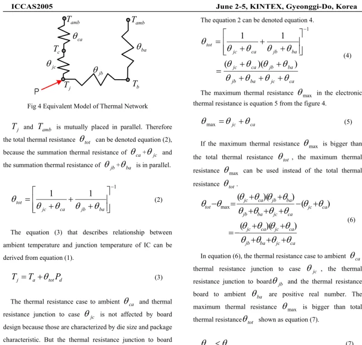
Fig 4 Equivalent Model of Thermal Network
j
T
andT
amb is mutually placed in parallel. Therefore the total thermal resistanceθ
tot can be denoted equation (2), because the summation thermal resistance ofθ
ca+θ
jc and the summation thermal resistance ofθ
jb+θ
ba is in parallel.1
1
1
−
+
+
+
=
ba jb ca jc totθ
θ
θ
θ
θ
(2)The equation (3) that describes relationship between ambient temperature and junction temperature of IC can be derived from equation (1).
d tot a
j
T
P
T
=
+
θ
(3)The thermal resistance case to ambient
θ
ca and thermal resistance junction to caseθ
jc is not affected by board design because those are characterized by die size and package characteristic. But the thermal resistance junction to boardjb
θ
and thermal resistance junction to ambientθ
ba is affected by board design like as board layer, parts arrangement and so on. Consequently, the total thermal resistance is variable according board design. So estimating junction temperature of IC is possible by using the thermal resistance case to ambientθ
ca and thermal resistance junction to casejc
θ
because those are not variable according board design. If the case temperatures of two ICs are same in same environment of power dissipation, the junction temperature of IC, which has lager thermal resistance, is high. Therefore if total thermal resistance is estimated larger than real total thermal resistance, the reliability of IC can be guaranteed with margin, when the junction temperature of IC is used as reliability standardThe equation 2 can be denoted equation 4.
ca jc ba jb ba jb ca jc ba jb ca jc tot
θ
θ
θ
θ
θ
θ
θ
θ
θ
θ
θ
θ
θ
+
+
+
+
+
=
+
+
+
=
−)
)(
(
1
1
1 (4)The maximum thermal resistance
θ
max in the electronic thermal resistance is equation 5 from the figure 4.ca jc
θ
θ
θ
max=
+
(5) If the maximum thermal resistanceθ
max is bigger than the total thermal resistanceθ
tot , the maximum thermal resistanceθ
max can be used instead of the total thermal resistanceθ
tot. ca jc ba jb ca jc ca jc ca jc ca jc ba jb ba jb ca jc totθ
θ
θ
θ
θ
θ
θ
θ
θ
θ
θ
θ
θ
θ
θ
θ
θ
θ
θ
θ
+
+
+
+
+
−
=
+
−
+
+
+
+
+
=
−
)
)(
(
)
(
)
)(
(
max (6)In equation (6), the thermal resistance case to ambient
θ
ca, thermal resistance junction to caseθ
jc , the thermal resistance junction to boardθ
jb and the thermal resistance board to ambientθ
ba are positive real number. The maximum thermal resistanceθ
max is bigger than total thermal resistanceθ
tot shown as equation (7).max
θ
θ
tot<
(7) From the equation (7), equation (3) can be denoted as euation (8), equation (9) and equation (10).d a j
T
P
T
=
+
θ
max (8) d jc c jT
P
T
=
+
θ
(9) d ca jc a jT
P
T
=
+
(
θ
+
θ
)
(10)Therefore it is possible to estimate the junction temperature from case temperature by using the thermal resistance
ca
θ
θ
jc. And the junction temperature from equation (7) is higher than real junction temperature, because the maximum thermal resistance is bigger than total thermal resistance. By using above principal, we can secure the reliability of IC withICCAS2005 June 2-5, KINTEX, Gyeonggi-Do, Korea
margin.
4. CONCLUSIONS
This paper discussed heat problem of IC, which composes the electronic instruments, to guarantee reliability of electronic instruments. And also proposed the unified equivalent model for various electronic instrument products to guarantee reliability and life of its parts like IC. By using the proposed model, thermal designer and developer, who have been hesitated during developing their products, can define reliability and life of their instruments. For future works, we should estimate the reliability margin.
ACKNOWLEDGMENTS
The authors gratefully acknowledge the contribution of Mr. Yong Oon Park, Soon Chang Kwon and LS Industrial Systems.
REFERENCES
[1] J.W. sofiz, “Thermal Resistance Measurement and Analysis Metheods for Hybrids and Multi-Chip Packages,”, Analysis Technology, Inc., Wakefield, MA, 1990.
[2] Bret A, Zahn “Steady State Thermal Characterization and Junction Temperature Estimation of Multi-Chip Module Packages Using The Response Surface Method” InterSociety Conference on Thermal Phenomena 1998. [3] Bcn Chambers, Tien-Yu Tom Lee, William Blood
“Thermal Analysis of a Chip Scale Package Technology,” Electronic Components and Technology Conference p-1407 -1412.
[4] Kevin Wood Allan Kirkpatriek, “Thermal Evaluation of Theta JA for Varying Board Conductivity,” IEEE Electronic Components and Technology Conference, pp. 792-797, 1996.
[5] James N. Sweet, William T. Cooley, “Thermal Resistance Measurements and Finite Element Calculations for Ceramic Hermetic Packages,” Sixth IEEE Semi-Theam Symposium, pp. 10- 16. 1990. [6] Robert L. Kozarek, “Effect of Case Temperature
Measurement Errors on the Junction-to-Case Thermal Resistance of a Ceramic PGA,” IEEE Seventh IEEE Therm Symposium, pp. 44 – 51, 1991.
[7] Bennett Joiner and Vance Adams, “Measurement and Simulation of Junction to Board Thermal Resistance and Its Application tin Thermal Modeling,” Fifteenth IEEE Semi-therm symposium, pp.212 - 220, 1999
[8] www.jedec.com
[9] www.amkor.com
[10] www.ti.com
[11] www.xilinx.com