53-2 / T.-S. Park
• IMID 2009 DIGEST
Abstract
A small temperature sensor is designed in a 0.35um CMOS process. Transistors operating in the intermediate inversion region are employed in the core of the sensor. This temperature sensor operates in -50℃
~120℃ with ±2℃ of accuracy after two-point
calibration. This temperature sensor can be placed in the active pixel area of a display panel to measure the temperature of the display panel for temperature compensation.
1. Introduction
In this work, we designed a CMOS temperature sensor (T-sensor) which can be used to compensate the temperature-dependent characteristics of flat panel displays, especially OLED. The brightness versus current characteristics of OLED devices vary significantly as a function of temperature. By measuring the temperature of the OLED devices and providing this information to OLED drivers, the temperature dependency can be compensated. To measure the temperature precisely, temperature sensors must be placed in the pixel array area. Therefore, the size of the sensor is very important in this application.
There have been considerable works on T-sensors designed using CMOS processes. However, most of the accurate sensors reported so far used BJT cores [1]. There also has been a work using MOSFET core operating in the subthreshold region [2]. These temperature sensors have high accuracy and good power efficiency. However, the core size of these sensors was too large to be used in the current application.
But it is not necessary that all component of the T-sensor are positioned in pixel array. Except by temperature detecting (core) device, other component can be located outside pixel array area.
We designed a CMOS T-sensor with a very small
core, which employs MOSFETs operating in the intermediate inversion region. This core can be located in pixel array area.
2. Proposed Temperature Sensor
In the strong inversion region, the I-V characteristic of a MOSFET is known to follow so-called square-law, whereas in the subthreshold region, it follows exponential function. In the intermediate region, however, neither of the models is accurate and an interpolation of two models is necessary. We found that in the intermediate region, the I-V characteristics can be described by following expression
(
)
2.5) /
(W L VGS Vth
I = βµ − (1)
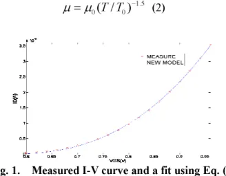
where β is a fitting parameter. Fig. 1 compares the I-V characteristic measured from an NMOS (1.2um/1.2um) and a fit to the measured data using (1). We can observe a very good match over a relatively wide voltage range.
On the other hand it is well known that the temperature characteristics of the carrier mobility in (1) can be expressed by 5 . 1 0 0( / )− =µ T T µ (2)
Fig. 1. Measured I-V curve and a fit using Eq. (1)
Small CMOS Temperature Sensor Using MOSFETs in the
Intermediate-Inversion Region
Tai-Soon Park1, and Sang-Gyu Park2
1
Division of Electrical and Computer Engineering, Hanyang University, 17
Haengdang-Dong, Seongdong-Gu, Seoul 133-791, Korea
TEL:82-2-2291-0375, e-mail: [email protected]
53-2 / T.-S. Park
IMID 2009 DIGEST •
Fig. 2. Schematic of the temperature sensor
Using these relationships, we designed a temperature sensor circuit of Fig. 2. In Fig. 2, (W/L)3=(W/L)4 and (W/L)1=K(W/L)2. (K=3 in our
design.) Using VGS1 = VGS2 + ID2R1 and (1) and (2), ID1
(=ID2) can be found to be proportional to the
temperature as follows. ⎟⎟⎠ ⎞ ⎜⎜⎝ ⎛ ⎟ ⎠ ⎞ ⎜ ⎝ ⎛ − ⎟⎟⎠ ⎞ ⎜⎜⎝ ⎛ ⎟⎟⎠ ⎞ ⎜⎜⎝ ⎛ = 0 3 / 5 5 / 2 3 / 2 1 0 3 / 5 1 1 1 1 ) / ( 2 1 T T K L W R ID βµ (3)
Using this, we can obtain a voltage drop proportional to temperature (VPTAT) across R4. In
order to convert this VPTAT signal into digital output, a temperature-independent reference voltage (VREF) is needed. VREF can be obtained by recognizing that the variation of VGS1 is complementary to the
temperature (VCTAT). Therefore, by adding VPTAT and VCTAT using current mirrors, VREF can be constructed.
Core transistors (M1 and M2) are small enough to be located in pixel array. Others in Fig. 2 are located out of the pixel array area.
3. Simulation Results
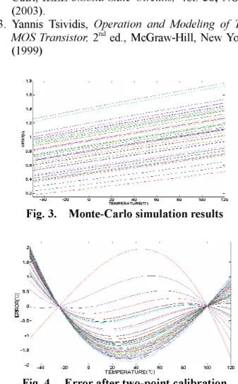
To test the feasibility of the sensor circuit, Monte-Carlo simulations of the circuit was performed using a 0.35um CMOS process. Fig. 3 shows the output PTAT voltage obtained from the simulations. Fig. 4 shows the temperature error after two-point calibration. The maximum error was ±2℃.
4. Conclusions
The proposed sensor circuit uses two small MOSFET transistors (M1 and M2 in Fig. 2) as core sensing circuit. The size of the core (< 70um2) is
drastically reduced when compared to BJT cores (>
500um2) or MOSFET cores operating in subthreshold
regions. Note that the part of the sensor circuit other than the core can be placed at a location where the area is not so critical. Therefore, we expect that the proposed sensor circuit can be utilized in the OLED pixel array for temperature compensation or any CMOS circuit where the small core-size is critical.
5. Acknowledgements
This research was supported by a grant (F0004061-2009-32) from Information Display R&D Center, one of the Knowledge Economy Frontier R&D Program funded by the Ministry of Knowledge Economy of Korean government.
6. References
1. Michiel A. P. Pertijs, Kofi A. A. Makinwa, and Johan H. Huijing, IEEE J.Solid-State Circuits, Vol.
40, NO. 12(2005).
2. G. Giustolisi, G. Palumbo, M. Criscione, and F. Cutri, IEEE J.Solid-State Circuits, Vol. 38, NO. 1
(2003).
3. Yannis Tsividis, Operation and Modeling of The MOS Transistor, 2nd ed., McGraw-Hill, New York,
(1999)
Fig. 3. Monte-Carlo simulation results