Journal of Magnetics 22(2), 266-274 (2017) https://doi.org/10.4283/JMAG.2017.22.2.266
©2017 Journal of Magnetics
Torque Ripple Reduction Using Torque Compensation Effect of
an Asymmetric Rotor Design in IPM Motor
Yong-Suk Hwang, Myung-Hwan Yoon, Jin-Cheol Park, and Jung-Pyo Hong*
Department of Automotive Engineering, Hanyang University, Seoul 04763, Korea
(Received 14 February 2017, Received in final form 26 March 2017, Accepted 27 March 2017)
In this paper, torques of two motors are compared by Finite Element Analysis (FEA). One has a symmetric rotor structure and the other has an asymmetric rotor structure. The comparison shows that the asymmetric rotor structured motor has reduced torque ripple compared to the symmetric. The torque of the compared motor models was analyzed by separating into magnetic torque and reluctance torque. Through the analysis of torque component separated, it is shown that the magnetic torque and the reluctance torque compensate each other in the motor with the asymmetric structure rotor. Here “compensate” means decrementing the effect of one or more harmonics. It is shown how this compensation appears between the magnetic torque and the reluctance torque by looking into back electro motive force (emf) and the relative permeability distribution of rotor core.
Keywords :asymmetric rotor structure, torque components separation, torque compensation, torque ripple
1. Introduction
The high torque ripple of Interior Permanent Magnet Synchronous Motors (IPMSMs) is common and inherent drawback [1-3]. The primary cause of torque ripple due to a motor are cogging effects, distortion of the magnetic flux density in the air-gap and the permeance difference between d and q axis. Higher harmonics of magnetic flux density in the air gap produce the field harmonic electro-magnetic torque, and the unequal permeance in the d and q axis produces the reluctance torque. Measures taken to minimize the torque ripple by motor design include elimination of slots, skewed slots, special shape slots and stator laminations, selection of the number of stator slots with respect to the number of poles, decentered magnets, skewed magnets, shifted magnet segments, selection of magnet width, direction-dependent magnetization of per-manent magnets (PMs) [4]. These measures are well-known and used commonly but they cause the increase of manufacturing difficulties and cost or the decrease of the average torque.
In case an electric motor rotates in both direction clock wise and counter clock wise, generally the same
charac-teristics are required in both directions. So such kind of motor should have a symmetric structure rotor design. In case a motor rotates in a single direction as for oil pumps or cooling fans, it might not to have a symmetric structure rotor. Therefore, it is possible to apply an asymmetric structure in order to reduce their torque ripples. A method reducing IPMSM’s torque ripple is introduced in [5] without the decrease of average torque by an asymmetric rotor. This method is easier and less complicated than the above mentioned methods for reducing torque ripple. However, it was not introduced in [5] how the rotor with asymmetric structure influences on the torque ripple. In this paper, the torque of two motors are compared by FEA. One motor has a symmetric rotor structure and the other has an asymmetric rotor structure. The comparison shows that the asymmetric rotor structured motor has reduced torque ripple compared to the symmetric. The torque of the compared motor models was analyzed by separating into magnetic torque and reluctance torque. Through the analysis of torque component separated, it is shown that the magnetic torque and the reluctance torque compensate each other in the motor with the asymmetric structure rotor. Here the meaning of “compensate” is follow-ing the definition in [6] as a meanfollow-ing of decrementfollow-ing the effect of one or more harmonic. It is shown how this compensation appears between the magnetic torque and the reluctance torque by looking into back electro motive
©The Korean Magnetics Society. All rights reserved. *Corresponding author: Tel: +82-2-2220-4466 Fax: +82-2-2220-4465, e-mail: [email protected]
force (emf) and the relative permeability distribution of rotor core. Through the above, it will be shown how torque ripple can be reduced by the application of an asymmetric structure rotor.
2. Analyzed Model and FEA Result
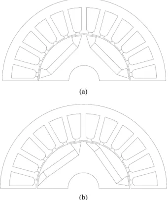
In order to compare the torque characteristics of two motors with a symmetric structure rotor and an asym-metric structure rotor, the two motor models with 4-poles 24-slots are analyzed by FEA. All specifications such as stator, magnet size, pole arc and material are the same except the arrangement of magnets in rotor. The analyzed models are shown in Fig. 1 and the common specifi-cations of the motors are shown in Table 1.
JMAG-Designer by JSOL corporation (Ver.15) was used for FEA. The FEA was executed on the condition of
sinusoidal current input and constant rotor speed. Torque waves from FEA are shown in Fig. 2(a). The average torque and the torque ripples of the two motor models are compared in Fig. 2(b). As shown in Fig. 2(b), torque ripple reduction effect of 31.3% appears in the asym-metric structure rotor without a significant average torque change. In order to analyze the reason that this kind of difference occurs between the two motor models, the torque of each model will be separated into the magnetic torque and the reluctance torque in the next section.
3. Torque Analysis using Component
Separation
The electromagnetic torque of IPM 3-phase synchronous motor can be calculated as (1) [7].
(1) T = 1 ωm --- e( aia+ebib+ecic) + 12--- ia2dLa dθ --- ib2dLb dθ --- ic2dLa dθ ---+ + ⎝ ⎠ ⎛ ⎞ + iaibdL--- + idθab bic--- + idLdθbc ciadL---dθca
Table 1. Common specification of the two motors.
Specification Values
Pole / Slot numbers 4/24
Stack length 45 mm
Stator outer diameter 86 mm Stator inner diameter 49 mm
Air gap length 0.5 mm
Fig. 1. Motor models (a) symmetric structure rotor (b) asym-metric structure rotor.
Fig. 2. (Color online) Comparison of torque waves and char-acteristics (a) symmetric structure rotor (b) asymmetric struc-ture rotor.
T : Electromagnetic torque [Nm] ωm : Rotor speed [rad/s]
ea, eb, ec : Back EMF by magnet in each phase [V]
ia, ib, ic : Current in each phase [A]
θ : Rotor position [rad]
La, Lb, Lc : Self inductance in each phase [H]
Lab, Lbc, Lca : Mutual inductance between phases [H]
The first term expresses the magnetic torque and the sum of remain expresses reluctance torque [7]. In order to obtain each term of (1) considering the saturation in the rotor and stator on the FEA condition, frozen perme-ability technique was applied. The frozen permeperme-ability technique transforms the non-linear problem in a linear, so that the electromagnetic torque can be calculated with (1) and the electromagnetic torque can be separated into magnetic torque and reluctance torque [7]. The operating point resulting in Fig. 2 was simulated. And then the flux-linkage by permanent magnet was obtained by the simu-lation which was done on a no load condition and the
same relative permeability with the operating point by frozen permeability technique. And finally the inductances due to the phase currents was obtained by the simulation which was done on the condition of no magnet and the same relative permeability [8]. All terms of (1) were
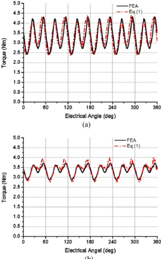
Fig. 3. (Color online) Comparison of torque waves from (1) and FEA (a) symmetric structure rotor (b) asymmetric struc-ture rotor.
Fig. 4. (Color online) Comparison of the averages of the torque waves.
Fig. 5. (Color online) Torque components separation (a) sym-metric structure rotor (b) asymsym-metric structure rotor.
obtained through the above procedure. The torque waves from (1) and FEA are compared in Fig. 3. And the aver-age torques of the torque waves are compared in Fig. 4.
From Fig. 3 and Fig. 4, we can find out that it is reason-able to use (1) for looking for the effect of the asymmetric structure rotor. The electromagnetic torques of the two motor models separated into two components are shown in Fig. 5.
The averages of the magnetic and reluctance torque wave of Fig. 5. are shown in Fig. 6. The motor model with the asymmetric structure rotor decreases in the average of the magnetic torque and increases in the average of the reluctance torque so that the total torque of the asymmetric structure motor is similar to the total torque of the symmetric structure motor as in Fig. 6(a). And there is no significant difference in torque ripple of each component as in Fig. 6(b). So we can notice that it’s hard to explain the torque ripple reduction as like Fig. 2 only with the magnitude of torque component.
Figure 7(a) compares the magnetic torque waves bet-ween the symmetric and the asymmetric motor models. The average of the magnetic torque decreased and a phase shift occurred in the asymmetric model. Figure 7(b) compares the reluctance torque waves. The average of the reluctance torque increased in the asymmetric model and the phases of the reluctance torque waves are almost the same. Considering the phase shift in the magnetic torque of the asymmetric model and reviewing Fig. 5, the mag-netic torque and the reluctance torque of the asymmetric model compensate each other, on the other hand those of the symmetric model don’t compensate each other. In summary of the analysis of Fig. 5, Fig. 6, Fig. 7, the average torque was maintained in the asymmetric model because the reluctance torque increased as the magnetic torque decreased and the torque ripple decreased dra-stically because the magnetic torque and the reluctance torque compensated each other due to the phase shift of
Fig. 6. (Color online) Analysis of torque component waves (a) Average (b) Ripple.
Fig. 7. (Color online) Comparison of magnetic and reluctance torque waves between the symmetric and the asymmetric (a) Magnetic torque wave (b) Reluctance torque wave.
the magnetic torque in the asymmetric model.
Harmonic analysis for the torque waves in Fig. 2(a) was done and is compared in Fig. 8. in order to research how the compensation occurs in the asymmetric model. The harmonic analysis was done by Fourier transform [9]. Figure 8 shows the amplitude of each harmonic for the torque wave in Fig. 2(a).
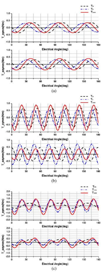
From Fig. 8, we can notice that the 6th and the 12th harmonic components are dominant during an electrical cycle. The 12th harmonic is the main cause of torque ripple particularly in the symmetric model. And the most obvious difference between the symmetric and the asymmetric appears on the amplitude of 12th harmonic. It can be noticed intuitively too through looking into Fig. 2(a). In order to look into the reason for the difference in total torque, harmonic analysis was done for the magnetic and reluctance torque of Fig. 5. And the 6th, 12th harmonics and the sum of them are shown in Fig. 9 without the constant components because we are interested in ripple.
In case of the 6th harmonic, there is no significant difference between the symmetric and the asymmetric models as in Fig. 9(a). In case of the 12th harmonic, the magnetic and reluctance torque of the asymmetric design have the phase difference around half cycle of the 12th harmonic so that the ripples of the magnetic and re-luctance torque compensate each other as in Fig. 9(b). On the other hand, the sum of the magnetic and reluctance torque in the symmetric design is larger than each com-ponent because the magnetic and reluctance torques have the phase difference around 1/4-cycle of the 12th harmonic as in Fig. 9(b). These results correspond with Fig. 8 very well. And the sum of the 6th and the 12th harmonics in each model are shown in Fig. 9(c), the wave shape of
Fig. 8. (Color online) Comparison of harmonic distribution for the torques of the two motor models.
Fig. 9. (Color online) Comparison of harmonic components for magnetic torque, reluctance torque and the sum of com-ponents in each model (a) 6th (b) 12th (c) 6th+12th.
each model corresponds approximately with the wave shape of Fig. 2(a).
It has been found out that the phase shift of the 12th harmonic in the magnetic torque make the torque reduced in the asymmetric model through the above harmonic analysis. In the next section, the reason of the phase shift of the 12th harmonic in the magnetic torque will be investigated.
4. Back EMF and Relative Permeability
in Rotor Core
The magnetic torque term in (1) consists of back emf, input current in each phase and rotor speed. Because sinusoidal current and constant speed were assumed, the shape of the magnetic torque wave can be investigated from the back emf of each phase. It has been presented that the phase shift of the 12th harmonic in the magnetic
torque is a main factor to the torque ripple reduction in 4-pole/24-slot motor with the asymmetric rotor structure. Because the magnetic torque is proportional to the product of back emf and current with the assumption of sinusoidal current, it can be derived that the 12th harmonic of magnetic torque due to the 11th and the 13th harmonics from the Trigonometric Identities
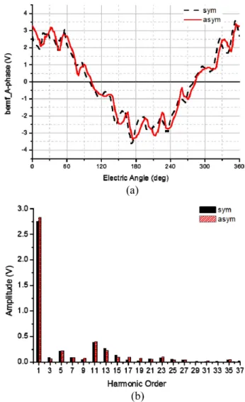
. Figure 10 shows the back
emf wave of a phase for the two motor model and the harmonic analysis result for the waves. In Fig. 10(a), the phase difference of harmonic components appear between the two motor models. And it is shown that the 11th and the 13th harmonics are dominant components in ripple from Fig. 10(b).
In order to look into the 11th and 13th harmonics of the back emf, those components reflecting the phase of them-selves are shown in Fig. 11. Figure 11(a) is comparing the sinαsinβ = 1
2
--- cos( (α β– ) − cos α β( + ))
Fig. 10. (Color online) Back emf of a phase and harmonic distribution (a) Wave of back emf (b) Harmonic distribution.
Fig. 11. (Color online) Comparison of main harmonics of back emf in the two motor models (a) the 11th harmonic (b) the 13th harmonic.
11th harmonic of the back emf in a phase of each motor model and Fig. 11(b) is for the 13th harmonic. It can be intuitively noticed that phase shifts are occurred in both harmonics by the asymmetric structure rotor.
From Faraday’s law, the back emf is expressed as (2) [7] (2) e : Back EMF [V] ψ : Flux-linkage [Wb] θ : Rotor position ω : Angular velocity
From (2), it can be noticed that the back emf is the rate of change of the flux linkage. And flux linkage can be expressed practically as (3) [7]
(3)
N : Number of turns Ф : Magnetic flux [Wb]
In (4), the magnetic flux Ф can be expressed with the surface integral of the normal component of flux density B when the magnetic flux crosses Ф surface S [10]
(4)
B : Flux density [T]
S : Surface
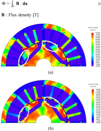
Therefore, the magnetic flux density distribution in the air gap influences on the back emf. The core saturation influences on the magnetic flux density distribution in air gap and the relative permeability in core is a function of the magnetic flux density [11]. Consequentially, the phase shifts in back emf and magnetic torque are due to the difference of relative permeability between two motor models. The relative permeability distribution of each model is shown in Fig. 12 and the low relative perme-ability areas are marked. The area with low relative permeability in the asymmetric model is larger than the area in the symmetric model. The difference in the relative permeability makes a difference in magnetic flux density distribution in air gap. And the difference in the flux density distribution in air gap causes the phase shift of the 11th and the 13th harmonic in back emf.
Summarizing, the change of relative permeability due to the asymmetric structure rotor causes the phase shift of the 12th harmonic in magnetic torque in said prior section. And the compensation between the 12th harmonic of magnetic and reluctance torques reduces the torque ripple. The effects of the asymmetric structure rotor are shown in e = ∂ψ ∂t --- = ∂ψ ∂θ --- dθ dt --- = ω ∂ψ ∂θ ---ψ = NΦ Φ =
∫
S B da⋅Fig. 12. (Color online) Comparison of the relative permeabil-ity distribution in cores (a) symmetric structure rotor (b) asymmetric structure rotor.
Fig. 13. The effect of the asymmetric structure rotor in the 4-pole/24-slot motor.
Fig. 13 in order.
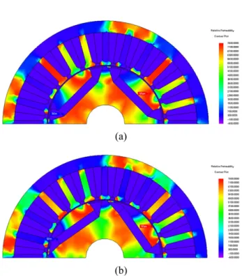
Additionally, the torque ripple reduction by the effect of the compensation due to the asymmetric rotor appears on the other operating conditions too. It is shown in Fig. 14. Besides the previously analyzed condition, at lower current input and higher current input, the torque ripple is reduced in the asymmetric rotor structured model. And the comparison of relative permeability distribution was shown in Fig. 15 at the lower current and in Fig. 16 at the
higher current. The distribution type in Fig. 15 and Fig. 16 is the same as Fig. 12. That means the method using the effect of compensation between magnetic torque and reluctance torque by applying the asymmetric rotor struc-ture is useful on the other operating condition not only the analyzed condition.
6. Conclusion
The two motor models with the symmetric and asym-metric structured rotor are compared, in order to find out how the asymmetric structured rotor makes the torque ripple reduction effect. From the result of the torque separation into the magnetic and reluctance torques, the average torque is maintained by the increase of the reluctance torque and the decrease of the magnetic torque in the asymmetric model. The compensation effect bet-ween the magnetic and reluctance torque is causing the torque ripple reduction. And it is shown that this kind of compensation is due to the phase shift of a specific harmonic in the magnetic torque. The phase shift of a harmonic in the magnetic torque is caused by the related phase shifts of harmonics in the back emf. The phase shift of some harmonics in back emf are due to the relative permeability distribution with the asymmetric rotor struc-ture. Therefore, the effect of torque ripple reduction can be expected by using a simple asymmetric rotor structure.
Fig. 14. (Color online) Comparison of torque waves on other operation points.
Fig. 15. (Color online) Comparison of the relative permeabil-ity distribution in cores on lower current condition (a) sym-metric structure rotor (b) asymsym-metric structure rotor.
Fig. 16. (Color online) Comparison of the relative permeabil-ity distribution in cores on higher current condition (a) sym-metric structure rotor (b) asymsym-metric structure rotor.
Acknowledgement
This research was supported by the MSIP (Ministry of Science, ICT and Future Planning), Korea, under the ITRC (Information Technology Research Center) support program (IITP-2017-2012-0-00628) supervised by the IITP (Institute for Information & communications Technology Promotion).
References
[1] L. Fang, S. O. Kwon, T. Sun, and J. P. Hong, ICEMS, 2010 Inter. Conf. on IEEE, 1239 (2010).
[2] N. Bianchi and S. Bolognani, ICEMS, 1222 (2000). [3] N. Bianchi and S. Bolognani, IEEE Trans. Ind. Appl. 45,
921 (2009).
[4] J. F. Gieras, C. Wang, and J. C. Lai, Noise of Polyphase Electric Motors, CRC Press (2005) pp. 80, pp. 102-105.
[5] M. H. Yoon, D. Y. Kim, S. I. Kim, and J. P. Hong, J. Magn. 20, 387 (2015).
[6] N. Bianchi, S. Bolognani, D. Bon, and M. D. Pré, IEEE Trans. Ind. Appl. 45, 921 (2009).
[7] J. R. Hendershot and T. J. E. Miller, Design of Brushless Permanent Magnet Machines, Motor Design Books (2010) pp. 178, 190-191, 211.
[8] J. A. Walker, D. G. Dorrell, and C. Cossar, IEEE Trans. Magn. 41, 3946 (2005).
[9] W. H. Press, S. A. Teukolsky, W. T. Vettering, and B. P. Flannery, Numerical Recipes in FORTRAN: The Art of Scientific Computing, Cambridge University Press (1992) pp. 490-498.
[10] A. E. Fitzgerald, C. Kingsley, and S. D. Umans, Electric Machinery, McGraw-Hill (2002) p. 3.
[11] B. Sheikh-Ghalavand, S. Vaez-Zadeh, and A. H. Isfahani, IEEE Trans. Magn. 46, 112 (2010).