26
MH Cache: A Multi-retention STT-RAM-based Low-power
Last-level Cache for Mobile Hardware Rendering Systems
JUNGWOO PARK, MYOUNGJUN LEE, and SOONTAE KIM,
Korea Advanced Institute of Science and TechnologyMINHO JU,
Samsung ElectronicsJEONGKYU HONG,
Yeongnam UniversityMobile devices have become the most important devices in our life. However, they are limited in battery capacity. Therefore, low-power computing is crucial for their long lifetime. A spin-transfer torque RAM (STT-RAM) has become emerging memory technology because of its low leakage power consumption. We herein propose MH cache, a multi-retention STT-RAM-based cache management scheme for last-level caches (LLC) to reduce their power consumption for mobile hardware rendering systems. We analyzed the memory access patterns of processes and observed how rendering methods affect process behaviors. We propose a cache management scheme that measures write-intensity of each process dynamically and exploits it to manage a power-efficient multi-retention STT-RAM-based cache. Our proposed scheme uses variable threshold for a process’ write-intensity to determine cache line placement. We explain how to deal with the following issue to implement our proposed scheme. Our experimental results show that our techniques significantly reduce the LLC power consumption by 32% and 32.2% in single- and quad-core systems, respectively, compared to a full STT-RAM LLC.
CCS Concepts: • Hardware → Non-volatile memory; Power estimation and optimization;
Additional Key Words and Phrases: Memory access pattern analysis, full system experiment, hardware ren-dering simulation
ACM Reference format:
Jungwoo Park, Myoungjun Lee, Soontae Kim, Minho Ju, and Jeongkyu Hong. 2019. MH Cache: A Multi-retention STT-RAM-based Low-power Last-level Cache for Mobile Hardware Rendering Systems. ACM Trans.
Archit. Code Optim. 16, 3, Article 26 (July 2019), 26 pages. https://doi.org/10.1145/3328520
This work was supported by the Korean Government (Ministry of Science, Information, and Communications Technology) through the National Research Foundation of Korea under Grant No. 2018R1A2B2005277. (Corresponding author: Soontae Kim.) Jeongkyu Hong was supported by the Korean Government (Ministry of Science, Information, and Communications Technology) through the National Research Foundation of Korea under Grant No. 2019R1G1A1003780.
Authors’ addresses: J. Park, M. Lee, S. Kim, M. Ju, and J. Hong; emails: {jw.park, leemj, kims, minhoju}@kaist.ac.kr, [email protected].
Permission to make digital or hard copies of all or part of this work for personal or classroom use is granted without fee provided that copies are not made or distributed for profit or commercial advantage and that copies bear this notice and the full citation on the first page. Copyrights for components of this work owned by others than the author(s) must be honored. Abstracting with credit is permitted. To copy otherwise, or republish, to post on servers or to redistribute to lists, requires prior specific permission and/or a fee. Request permissions [email protected].
© 2019 Copyright held by the owner/author(s). Publication rights licensed to ACM. 1544-3566/2019/07-ART26
of their limited battery capacity. This challenge becomes more important, because the energy con-sumption of recent mobile devices is continuously increasing to support higher computing power; the mobile devices have more CPU cores operating at higher frequencies, larger screen sizes, higher resolutions, and so on.
The energy consumption of on-chip cache is an important problem in mobile systems for the following reasons. First, many prior works and reports note that the energy consumption of CPUs in modern mobile systems is an important problem. The work in Reference [7] presents a detailed power consumption breakdown of each component in smartphones with different scenarios. Ac-cording to the authors, when a smartphone is in a suspended state, the GSM network module is the first power drainer and the CPU is the second. Even in video playback, the second power consumer is the CPU. They note that the CPU power consumption problem becomes more severe, because faster CPUs are adapted to smartphones. Moreover, it is expected that the current CPUs in smart-phones consume much more energy than those reported in Reference [7]. The CPU model used in the experiment operates at a 400MHz clock frequency and is single-core. CPUs in the latest mobile systems operate at clock frequencies of approximately 2.7GHz and are adapting octa-core proces-sors with larger cache memories [41]. In other work [22], it is reported that processors consume more than 30% of the total energy consumption of the mobile devices when the screen brightness is at the maximum. Second, the energy consumption of on-chip cache contributes largely to that of CPUs. Reference [43] reports that 12% (computational) to 45% (non-computational) of proces-sor power consumption is caused by on-chip cache. Reference [43] also reports that cache is an important factor to reduce CPU power consumption. The study in Reference [13] shows a detailed energy consumption analysis of uncore (including last-level cache) and core components. In this paper, uncore components consume large amounts of power as compared to core components. In conclusion, cache is one of the most power draining components in modern mobile systems. This motivates us to explore an energy-efficient LLC design.
With its strong capability in reducing leakage energy consumption, non-volatile memories (NVMs) such as spin-transfer torque RAMs (STT-RAMs) [29,48] have been introduced increas-ingly into processors as LLCs in mobile systems [33,35,47]. However, a blindly designed STT-RAM-based LLC can be inefficient, because write operations of STT-RAMs consume significant amount of energy (several times of that of SRAMs) [51]. Several prior works have addressed this problem. References [1,24,53] reduce the dynamic energy consumption of STT-RAM-based LLCs by reducing the number of write accesses to the LLCs. References [44,49] propose hybrid LLC architectures of SRAM and STT-RAM. The main idea of the works is to allocate write-intensive cache lines in SRAMs. One limitation of the works is that they did not consider the full system environment with operating system (OS), therefore the impact of OS kernel on mobile systems is not addressed.
The state-of-the-art works [51,52] propose an energy-efficient LLC design for mobile systems, which is based on multi-retention STT-RAM. In the works, LLC space is partitioned into two par-titions: short-retention STT-RAM and long-retention STT-RAM partitions, and kernel process is allocated to the long-retention STT-RAM partition while user processes are allocated to the short-retention STT-RAM partition. The rationale is that kernel process has relatively low writes and cache misses, compared to user processes.
MH Cache 26:3 The limitations of state-of-the-works are as follows. First, they partition LLC space between
kernel and user processes based on the brief tendencies of kernel process in terms of cache writes,
portion of misses, lifetime of data on LLC, compared to the summation of all user processes, which consist of almost Linux processes. This results in placing kernel process to a long-retention STT-RAM partition, where write operation is expensive. However, the impact of kernel process on multi-retention STT-RAM-based LLCs has been underestimated. We observed that kernel process incurs a large number of program operations (i.e., modification in a cache line due to a cache miss).1
As a result, cache write operations on long-retention STT-RAM occur frequently. This will cause unnecessary energy consumption. Second, the works adopt a simple way-based cache partition-ing; they allocate the long-retention LLC segment to kernel process and the short-retention LLC partition to user processes. The problem of the partitioning is that non-write-intensive user pro-cesses still access the short-retention LLC partition, even though it is better to place the cache lines of these processes to the long-retention LLC partition. Third, since the works have been imple-mented and simulated an Android version that supports software rendering only in gem5 [6], it is difficult to measure the impact of the works on realistic environments. It is reported that Android OS with software rendering show largely different behavior from those with hardware rendering [9], thus a study with hardware rendering is required.
To resolve the problems above, in this article, we propose a Multi-retention cache for Mobile
Hardware rendering system (MH cache), a new multi-retention STT-RAM-based LLC
architec-ture and its management scheme for mobile systems with hardware rendering. The management scheme includes a proper cache partitioning and a cache line placement policy considering the memory access characteristics of kernel and user processes including background services in mo-bile systems.
We make the following contributions:
• We provide a deeper insight on the memory access behaviors of the kernel and user
processes in realistic mobile systems, by simulating mobile full systems with hard-ware rendering. Unlike the state-of-the-art works [51,52] that evaluated their schemes in mobile systems with software rendering, in our study, we studied realistic mobile systems and the impact of the kernel and user process behaviors on the systems.
• For a better cache partitioning of kernel and user processes in multi-retention
STT-RAM-based LLCs, we introduce a better metric for cache partitioning: the number of cache programs per lifetime. The metric provides the write-intensity (cache data
modifi-cation) of a process dynamically. In References [51,52], they used the tendencies of write operations to LLC, LLC miss portion, retention time of user, and kernel processes to justify their simple cache partitioning. However, they do not present a mathematical metric and they simply allocate kernel process to long-retention STT-RAM part and user processes to short-retention STT-RAM part.
• Based on the observations and insight from the first and second contributions, we
propose a novel multi-retention STT-RAM-based low-power LLC architecture. Our
proposed LLC architecture reduces the energy consumption of the systems, by allocating short-retention STT-RAM partition to kernel process and classifying user processes intelli-gently based on their cache programs per lifetimes. In our evaluations, our proposed scheme presents lower energy consumption with small area and performance overheads over a full STT-RAM of the same capacity and a state-of-the-art energy-efficient LLC scheme in a
1In this article, we define a cache program as the sum of cache write hits and cache misses. Please note that program
operations cause similar effect to write operations, because they modify the content of a cache line also. This operation incurs write energy consumption. We will discuss the metric later in greater detail.
based on hardware rendering systems that show significantly different memory access be-haviors from that of software rendering systems because of the rendering-related tasks. MH cache presents reduced LLC power consumption by 32% and 32.2% in single- and quad-core systems, respectively, compared to a full STT-RAM with the same capacity. Compared to a state-of-the-art scheme, our proposed MH cache presents average 15.7% and 33.1% lower LLC power consumption in single- and quad-core systems, respectively.
The remainder of this article is organized as follows. In Section2, we introduce the related work and background. In Section3, we present our motivation, process behavior analysis, pro-posed scheme, detailed implementation, and following issue. We show the experimental results in Section4. We deal with additional issue in Section5, and conclude the article in Section6.
2 RELATED WORK AND BACKGROUND
2.1 Related Work
STT-RAM has many advantages, such as high density and low leakage power consumption. How-ever, it consumes large write dynamic energy. Many studies attempt to reduce the write dynamic energy of the STT-RAM. Early write termination [53] is proposed to reduce the write dynamic energy based on each cell. If the old value and the new value that will be written are the same, then the write operation is not performed. The work in Reference [24] proposed sub-block-based STT-RAM L2 cache management policy to reduce the write amount of STT-RAM. The work in Reference [1] predicts and bypasses dead writes for write energy reduction. It uses a PC-based prediction table to predict whether a cache line is dead. To implement this scheme, every L1 cache line has a partial PC field to determine the corresponding PC value of the write operation when a writeback occurs to the LLC. The work in Reference [26] investigates the possibility of using STT-RAM instead of DRAM as a main memory. This work proposes partial write and row buffer bypass to improve STT-RAM main memory performance and energy. The work in References [12,
37] tries to extend lifetime of STT-RAM to utilize STT-RAM as cache memories.
Similar to STT-RAM, another emerging memory technology, the phase-change memory (PCM) has issues with the write operation: slow write speed and high write power consumption. To re-solve this problem, many papers have been published. The work in Reference [38] proposed write cancelation and write pausing to reduce the increased latency due to read requests. The work in Reference [40] proposed a PCM-based hybrid main memory system with a small DRAM buffer. This architecture utilizes the latency benefits of DRAM and the capacity benefits of PCM. The work in Reference [27] utilizes buffer reorganizations and reduces the delay and energy gap between PCM and DRAM. The partial write operation proposed in this paper increases memory endurance, providing a lifetime of 5 to 6 years. The work in Reference [28] attempted to utilize PCM as ideal main memory by buffer sizing, row caching, write reduction, and wear leveling. In conclusion, writing policy in emerging memory technology will affect system performance, energy consump-tion, and reliability. Therefore, we need to focus on handling the side effects accompanying the adoption of these emerging memory technologies.
We have discussed the write problem in the emerging memory technology. However, read and write operations have different characteristics even in traditional SRAM cache-based system. Ref-erence [23] addresses that it can improve the system performance to prioritize read operations
MH Cache 26:5
Fig. 1. Related works and our proposed MH cache. (a) Introduces hybrid cache with various memory cells [50]. (b) Proposed 3D stacked MRAM-based L2 cache [44]. (c) Proposed STT-RAM-based multi-retention cache and the criterion of placement is the cache line belongs to kernel or not [52]. The last one is our proposed cache management scheme, MH cache. Our MH cache has detailed data placement algorithm to consider process behavior.
over write operations in caches. This is because write operations are not on the critical path as the latencies of those operations can be hided by buffering. To utilize the characteristics, the work proposes a cache insertion policy that prioritizes read lines over write lines in the caches, which is based on Dynamic Insertion Policy (DIP) proposed in Reference [39]. To predict the future read cache line, a PC-based read reference predictor is proposed. Although the paper gives a deep in-sight on the different characteristics between read operations and write operations in caches, the following are its differences from our work. First, our work aims STT-RAM-based caches, where the write operations have larger cost than in SRAM caches. In STT-RAM-based caches, a more ag-gressive cache partitioning technique is needed because of the expensive write operations. Second, our works aim to reduce the energy consumption of the mobile system, as well as to improve the performance. This motivates us to explore a multi-retention STT-RAM-based LLC architecture. Third, the work in Reference [23] does not consider the full system environment. Therefore, the impact of the kernel process on caches is not well studied.
Many studies exist on the hybrid cache of volatile and non-volatile memory cells. Hybrid caches are proposed to reduce the total dynamic energy consumption of cache by reducing the number of writes in STT-RAM and increasing the number of writes in SRAM. It reduces the total dynamic energy, because write dynamic energy consumption of STT-RAM is larger than that of SRAM. Fig-ure1describes various hybrid caches. Wu et al. [50] introduced the concept of hybrid cache and explained the implementation of a hybrid cache in detail. They showed various hybrid cache con-figurations. However, they used different cache cells for each cache level: SRAM for L2; eDRAM, MRAM, and PRAM for L3; and PRAM for L4. Our work only focuses on reducing the power con-sumption of the LLC, which is the most power consuming component in the CPU.
Sun et al. [44] proposed a three-dimensional stacked hybrid LLC of SRAM and STT-RAM for chip multiprocessors. In their work, a simple migration policy was proposed. If two consecutive write operations are requested in a certain cache line in an STT-RAM, then this line is migrated to the SRAM. However, this policy cannot handle no-write operations on the line after two consecutive writes. In our work, because the placement criteria is measured continuously and dynamically, this problem does not occur.
In Reference [49], Wang et al. proposed the placement and migration policy for STT-RAM based on a hybrid cache. In this scheme, prefetched cache lines are placed on the SRAM part and the oth-ers are placed on the STT-RAM part. Similar to Reference [1], it requires storing PCs to all L1 cache lines. The target system of [49] is a 4GHz, high-performance desktop PC system with a 4.5MB L2 cache, and they did not consider the operating system (OS). We analyzed many background
Fig. 2. L2 cache access percentage observation from References [51,52]. This observation is quite different from ours. The access percentage of kernel of our observation will be discussed in Section3.3.
processes, i.e., those that are executed when the OS is running, and we propose a cache manage-ment scheme for mobile OS-based devices.
Yan et al. [51] proposed an energy-efficient multi-retention cache design (EECD) for mobile platforms. Their work is extended to Reference [52]. In their observation, the kernel generates ap-proximately 50% of the total LLC accesses. This is described in Figure2. Thus, their work divides the LLC into two parts with the same capacity. In Reference [51], the lifetime of the cache lines of the kernel process is long. However, for user processes, the lifetime of the cache lines is relatively short. Therefore, only the kernel process uses the long-retention STT-RAM part, while the other processes use only the short-retention STT-RAM part. In the extended EECD [52], they consid-ered the cases when the kernel or user processes’ memory requirements are larger than half of the LLC. To handle these cases, the EECD uses algorithms to utilize the other side’s memory area. When a kernel shows a stride pattern or requires many memory accesses within a certain period, the kernel can access the cache area for user processes (short-retention STT-RAM) and vice versa. However, the baseline of the EECD is SRAM and the EECD does not show the comparison with pure STT-RAMs. Moreover, they do not show their scheme on multi-core systems. Furthermore, in our observation, the kernel process occupies a smaller portion (15% on average) of the total LLC accesses compared to the EECD. Our observation of the percentage of kernel accesses for all benchmarks on hardware rendering is shown in Section3.3. The difference in observations can be attributed to several reasons. In the EECD, Android ICS(4.0.x) [14], which only supports soft-ware rendering simulations, is used. However, we used Android Kitkat(4.4.4) [16], which supports hardware rendering in gem5 [6] simulator. Therefore, EECD in References [51] and [52] used only software rendering systems. EECD divides processes into kernel and user processes. It is not effec-tive if a kernel occupies a small portion of the total LLC accesses. Thus, we analyze and categorize the processes in more detail than the EECD.
2.2 Background
2.2.1 Short-retention STT-RAM Cache. The works in References [42, 45] introduce short-retention STT-RAM, which reduces write dynamic energy and latency of STT-RAM by reducing data retention time. This can be achieved by reducing the area of free layer [42]. Reference [45] shows two types of data retention time reduced STT-RAM; 26.5 μs and 3.24 s. Because of reduced write dynamic energy and latency, the work in References [42,45] utilizes STT-RAM cells in all cache levels. However, their STT-RAMs require periodic refresh operations to retain the data. The work in Reference [42] used DRAM style refresh (refresh all cache lines). To reduce the number
MH Cache 26:7
Fig. 3. Gem5 full system modeling. (a) Shows software renderer works instead of a real GPU. (b) Shows full system model with NoMali [9]. This figure is quoted from Reference [3].
Fig. 4. Relative error rates compared to real GPU [3].
of refresh operations, data retention monitor is used in Reference [45] but it also incurs additional area and energy overhead. References [30] and [31] attempts to reduce the number of refreshes using cache coherence protocol and compiler assistance, respectively.
2.2.2 Hardware Rendering Simulation with NoMali. Figure3shows how NoMali [9] operates in the gem5 full system simulation environment. In Figure3(a), the software renderer operates instead of the real GPU, because a GPU does not exist in Figure3(a). However, most commercial smartphones have a GPU; thus, this is unrealistic. In the case of Figure3(b), the GPU driver operates and has a GPU, NoMali. NoMali proposed fake GPU drivers to avoid being misled by memory accesses by software rendering. NoMali only mimics the instructions transferred between CPU and GPU, but a detailed GPU is not modeled. Thus, NoMali does not render anything. However, the memory operation is shown when the GPU is used for rendering. This means that we can observe non-polluted memory operations by a graphic rendering process.
Figure4shows the actual error rates caused by software rendering. Graphic rendering of base-line is performed by a GPU in a real system. This problem and solution are previously presented in Reference [9]. However, hitherto, many researchers have not considered or included the errors caused by software rendering. It is noteworthy that Android image and Linux kernel provided by Moby [20], which is a widely used mobile benchmark suite, support only software rendering in the full system simulation and most full system researches used it. However, this article considers
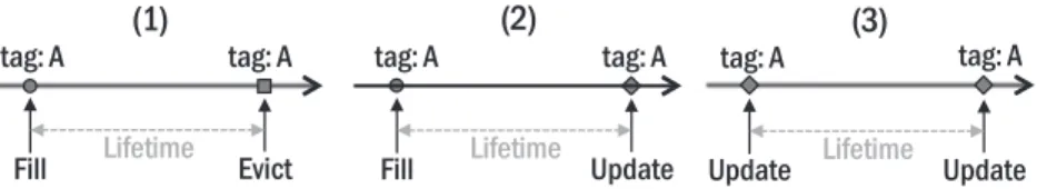
Fig. 5. Three examples of cache line lifetime. In our scheme, each cache line has their own life time. We calculated the average lifetimes of all cache lines for each process. This figure is quoted from Reference [1].
hardware rendering and shows how the rendering method affects the process behaviors. We in-vestigated hardware rendering with NoMali. MH cache is much more realistic than other related works and shows noticeable power reduction compared to the EECD [52] and a pure STT-RAM LLC.
3 MULTI-RETENTION CACHE FOR MOBILE HARDWARE RENDERING SYSTEMS
3.1 Motivation of Process Behavior Analysis
While the Adobe and BBench [19] applications are executing, the total number of executed pro-cesses are 201 and 200, respectively, in our experiments. Most of them are background propro-cesses of the Android OS. Unlike the general PC or server system, an Android device, which is a represen-tative mobile platform, executes many core and background services. Applications depend on the library of the Android framework and services. For example, most of applications respond to the user touch events. To obtain an event from the input system in Android services, the application is connected with the Binder IPC mechanism. Hence, the application typically combines Android services such as activity manager, window manager, location service, input manager service, web service, and video/audio service. In addition, the application in mobile devices are almost GUI-based. Therefore, considering the method of graphic rendering is important. Since the Android OS 4.0 (Ice Cream Sandwich), hardware rendering has become the default drawing configuration [15]. Thus, we analyze the behavior of each process when the Android system executes benchmark applications and investigate the software and hardware rendering systems.
3.2 Process Behavior Analysis
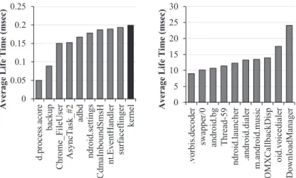
In this section, we address why rendering method is important and how it affects processes’ be-haviors. We calculated the average lifetime of all cache lines and the number of cache writes by each process for all the benchmarks executed to analyze the processes’ behavior. The examples of cache line lifetime is shown in Figure5, which is classified in three cases: (1) the duration of cache filling to eviction, (2) the duration of cache filling to update for the same cache line, and (3) the duration of cache update to another update. The average lifetime of all cache lines per process is traced. Figure6shows an example of the average lifetimes of processes for each LLC (in our experimental environment, L2 cache is the LLC.) on a software rendering system. Some applica-tions have a very short lifetime under 0.1 ms, as shown in the left chart of Figure6, whereas some applications have a long lifetime that is over 15ms, as shown in the right chart. Figure7shows the same experimental results on the hardware rendering system. Particularly, the kernel shows a noticeably different behavior compared to software rendering. In software rendering (Figure6), the average lifetime of a kernel is approximately 0.2ms. However, in hardware rendering (Figure7), the average kernel lifetime is approximately 50ms, which is much longer than that of software ren-dering. This is obvious, because the rendering system affects the most important process kernel’s behavior. It means that other processes will have different behaviors and the rendering method is very important.
MH Cache 26:9
Fig. 6. Short (left) and long (right) average cache line lifetime processes in LLC while adobe runs for 10s on software rendering system.
Fig. 7. Short (left) and long (right) average cache line lifetime processes in LLC while adobe runs for 10s on hardware rendering system.
3.3 Multi-retention Cache for Hardware Rendering
3.3.1 Classification. In this article, to avoid confusion, we call write (data modification)
opera-tions on cache as cache programs, which are defined as Equation (1):
Cache_Programsi= Cache_Write_Hitsi+ Cache_Missesi. (1)
i in every equation means the process number. Long-retention STT-RAM has a large write
dy-namic energy. Thus, whether the data should be placed in short- or long-retention STT-RAM is the primary issue in multi-retention cache management. To address this issue, we propose a new metric, i.e., the number of cache programs per lifetime for each process to measure write-intensity of each process dynamically. We shorten the name of this metric to programs per lifetime (PPL) (Equation (2)). The cache program incurs write dynamic energy; thus, this operation should be avoided in long-retention STT-RAM cells. We measured the number of cache programs for each process. However, the number of cache programs itself does not imply write-intensity of a process.
Fig. 8. Top five (left) and bottom five (right) PPL processes for all benchmarks with software rendering.
Fig. 9. Top five (left) and bottom five (right) PPL processes for all benchmarks with hardware rendering.
Thus, we considered both parameters; the number of cache programs and the cache line lifetime: Programs_per_lifetimei=
Cache_Programsi
Average_Lifetimei
. (2)
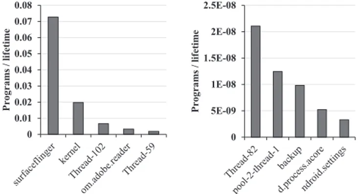
We measured the PPL for all processes and for all five mobile benchmarks used in this work for both software and hardware renderings. We summarized the top five and bottom five processes of the PPL on software rendering and hardware rendering in Figures8and9, respectively.
As shown in Figure8, surfaceflinger and kernel processes show larger PPL than others, which can be attributed to software rendering. Surfaceflinger comprises some surfaces on one screen image and passes this image to the framebuffer. Thus, the copybit operation is frequently called in surfaceflinger. If the hardware accelerator (GPU) is supported, then this operation is performed by the hardware. In software rendering, this operation is performed by the software and the CPU. Consequently, surfaceflinger shows very frequent cache programs, as shown in Figure8, caused by software rendering. Because the framebuffer is located in the kernel area of the memory space, the
kernel process also shows frequent cache accesses caused by software rendering. These operations
are not performed in the real devices. The third process, Thread-102, shows a relatively larger PPL than other processes but this process is a randomly generated process and the number of cache programs is small. The fourth (om.adobe.reader) process is the benchmark application process, which shows relatively large program numbers, but those lifetimes are very long compared to the surfaceflinger and kernel. In contrast, with hardware rendering, the PPLs of those processess become much smaller, which are the 21th and 109th among the 254 processes (the sum of processes
MH Cache 26:11 Table 1. The PPL Ranks of kernel for All Benchmarks
with Hardware Rendering
Fig. 10. The LLC access ratios of top 15 access processes. We calculate the sum of all accesses for all bench-marks on hardware rendering single-core system.
Fig. 11. The LLC program ratios of top 15 program processes. The experimental configuration is the same as Figure10.
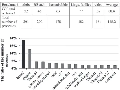
in all benchmarks), respectively. Table1shows the PPL rank of the kernel in each benchmark with hardware rendering. On average, the PPL rank of the kernel is the 60.4th among 188.2 processes. However, as shown in Figure10, the kernel still presents a considerable number of cache accesses compared to other processes, i.e., 18.7% of the total number of cache accesses. Figure11shows the top 15 cache program processes. The kernel rank in this figure is the 10th.
The kernel is a core process in an operating system. Kernel is needed in every system call, and it is in charge of process scheduling and inter-process communication (IPC), memory, and network management. Thus, kernel should be frequently accessed and programmed than others as shown in Figures10and11. Thus, we regard the kernel should be placed to short-retention STT-RAM cells. In our scheme, the processes that show a larger PPL than that of the kernel and the kernel itself are placed to short-retention RAM to reduce the write dynamic energy of long-retention STT-RAM. In the first placement, if a process is not a kernel, then the process is placed to long-retention
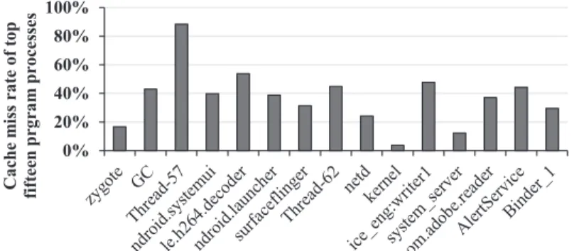
Fig. 12. The cache miss rates of top fifteen program processes. The experimental configuration is the same as Figures10and11.
STT-RAM. During system running, this process will be placed into short-retention STT-RAM cells if the PPL of this process becomes larger than that of the kernel.
3.3.2 Partition Size. Deciding the cache partition size between short- and long-retention
STT-RAM is a critical design point to achieve low-power consumption in multi-retention STT- STT-RAM-based LLCs. The cache program ratio of the top 10 processes of Figure11is 60% of the total cache programs, and the PPLs of these processes are larger than that of the kernel. To reduce the total dynamic energy consumption of the proposed multi-retention cache, these processes should be placed to short-retention STT-RAM. In our consideration, the cache lines in these processes will be evicted, even if they have more cache ways [2,21]. The cache miss rate of the top 15 program processes is described in Figure12. In our work, we observed that a small number of short-retention STT-RAM ways is a good design choice. In our experiments, we utilized various cache partitioning (e.g., 2-way short- and 14-way retention STT-RAM cache, 3-way short- and 13-way long-retention STT-RAM cache, and 4-way short- and 12-way long-long-retention STT-RAM cache). If the number of short-retention STT-RAM cache ways is reduced, then the number of cache misses in the short-retention STT-RAM cell will be increased [2,21]. Thus, we focus on the number of cache misses and the modified PPL formula, as described in Equation (3). ω is the weight for cache misses:
Programs_per_lifetimei=
Write_Hitsi+ ω ∗ Cache_Missesi
Average_Lifetimei
. (3)
3.4 Detailed Implementation and Overhead
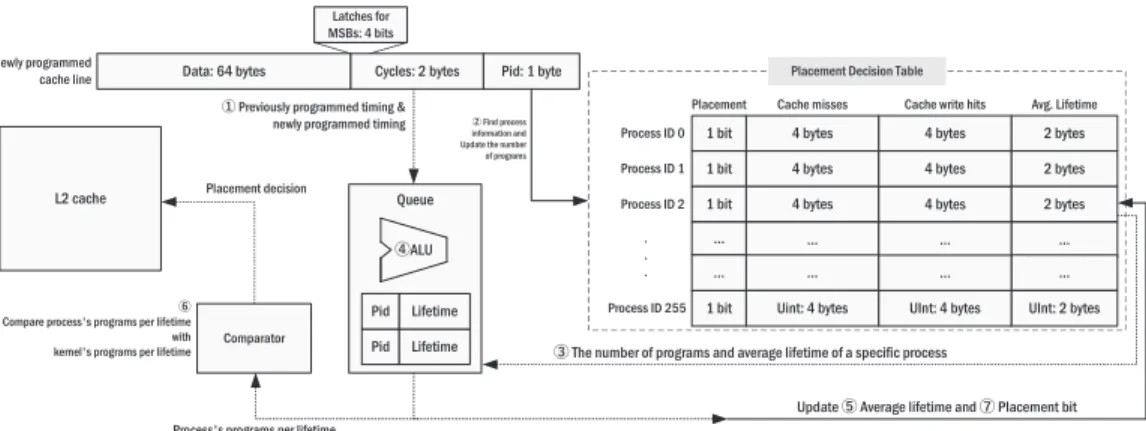
Cache line placement algorithm. Figure13describes the flow chart of our MH cache place-ment algorithm. When a cache program request occurs on a cache line in the L2 cache, MH cache identifies whether the cache line to be written belongs to kernel process. If the cache line belongs to the kernel process, then it is always placed to short-retention STT-RAM. On the other hand, the cache line does not belong to the kernel process (i.e., user process), MH cache calculates the PPL of the process that the cache line belongs to. Subsequently, MH cache compares the calculated PPL with that of the kernel. If the PPL of the process is larger than that of the kernel, then the line is placed to the short-retention STT-RAM. Otherwise, the line is placed to long-retention STT-RAM. Figure14shows the entire picture of our proposed MH cache. To store the number of programs and the average lifetime of each process, a table called a placement decision table is required. This table is placed in short-retention STT-RAM area. The detail of this overhead will be covered in Hardware overheads section. The largest number of processes in each benchmark used in our experiments does not exceed 210. Based on this result, we assume that the possible maximum
MH Cache 26:13
Fig. 13. Overall flow chart of MH cache. By calculating PPL of process of newly programmed cache line and using PPL value of kernel, MH cache decides the cache line placement region.
Fig. 14. Progress of how to calculate PPL of each process. To calculate this value, additional storages (place-ment decision table, storage for kernel’s lifetime, timing and process id fields in each cache line) are required.
number of processes for an application is not larger than 255. Thus, we used one byte (8 bits; that can represent 256 pieces of information) to represent the process id, which is the index of the placement decision table. Eight bytes are used to represent the number of cache write hits and cache misses for each process. These fields are implemented using counters and are accessed and increased for every cache program in the LLC.
To calculate the average lifetime per process, the lifetime of each cache line is required. To obtain this information, each cache line should store the timing when the cache line is programmed. We do not store the entire cache programmed timing, because we focus on the lifetime (duration) of the cache line, not the exact programmed timing. We store the 16-bit right-shifted system cycle to
1. When the lifetime of the last programmed cache line is calculated, the new average lifetime of a process can be calculated. Because the number of programs and the average lifetime are presented from the placement decision table3, which is index by Pid 2, the total lifetime of all programs can be calculated by multiplying the number of programs and the average lifetime. The new total lifetime is calculated by adding the previous total lifetime from the placement decision table and the lifetime of the newly programmed cache line (Equation (4)):
Total_Lifetimeinew= Total_Lifetimeiprev+ Lifetimeinew. (4)
The new number of cache misses or cache write hits is calculated by adding the number of previous values from the table and one (by incrementing the counter)2. By dividing the new total lifetime by the new number of programs, the new average lifetime can be calculated (Equation (5)):
Avg_Lifetimei=
Total_Lifetimei
Write_Hitsi+ Cache_Missesi+ 1
. (5)
These calculations are performed by an external ALU4 that supports these operations attached on the LLC. After calculation, the table of average lifetime is updated by the newly calculated value 5. To calculate the average lifetime of each process, two bytes are used to store the programmed cycle and this value is stored in the data area of the cache line. Thus, the data of each cache line is 67 bytes (64 bytes for data + 2 bytes for programmed timing + 1 byte for process id, which is used for index of placement decision table). One cache program updates the number of cache programs and the average lifetime of the corresponding process.
To calculate the average lifetime of each process, one shift operation to obtain shifted cycles, one subtraction to obtain the lifetime of the last programmed cache line, one increments to update the number of cache misses or cache write hits, one addition to obtain the all cache programs, one multiplication to obtain the total lifetime, one shift operation to give weight on cache misses, and one division to obtain the new average lifetime, are required. Except the shift operation to store the Cycles, these calculation are not required at the moment when the cache line is programmed, because the targeted value is the average lifetime of process the cache line belongs to, not the lifetime of the evicted data itself. The average lifetime value will not change significantly when the data collected are sufficient. Thus, this operation is queued and performed when a cache miss occurs, to hide the performance overhead. The ALU unit is only powered when this calculation is performed to reduce energy consumption4. An element of this queue should store the process id and lifetime of the last programmed cache line: Cycles in Figure14. Only these two pieces of information can be stored to obtain the new average lifetime, because the previous number of programs and the previous average lifetime can be derived from the placement decision table, which is indexed by the process id. Thus, three bytes are required for each queue element. In our experiment, the global data miss rate is approximately 5.7%. Thus, a large calculation queue is not required, because the cache misses occur frequently. We decided the number of queue element to be 16, which is the number of MSHRs in our environment. The total size of this queue is 48 bytes. This queue is accessed when an LLC program occurs. Our scheme compares PPL of a kernel and that of other processes6. Thus, storing the PPL of a kernel can reduce the number of calculations, because this value is required very frequently for classification. The PPL value of a kernel is stored
MH Cache 26:15 in another external storage, which requires four bytes. After comparison, placement bits, which are located in the placement decision table, are set to handle overflow state7.
Overflow handling. In our work, we used two bytes of the Cycles field to represent the interval
between two consecutive programs to the line. The value of the Cycles field increments by one every 65,536 system cycles. It means that Cycles field represnets 4,294,967,296 system cycles. It is noteworthy that using two bytes of the Cycles field is acceptable for the following reason. In our experiments, for example, the maximum average lifetimes for all process of the all benchmarks is 230,765,531 cycles. However, because the Cycles field has a limited length, an overflow can occur when the system cycle exceeds 4,294,967,296.
ALGORITHM 1: Overflow handling algorithm for Cycles (in newly cache programmed line) field 1: if Four MSBs of Cycles field are 1 then
2: Overflow bit← 1 3:
4: Cycles field is initialized to 0 and increments again in every 65,536 system cycles. 5:
6: while 4th MSB of Cycles = 0 do
7: if Placement bit of newly programmed process= 1 then 8: Place this cache line to short-retention STT-RAM
9: else
10: Place this cache line to long-retention STT-RAM 11:
12: if 4th MSB of Cycles= 1 then 13: Overflow bit← 0
14: Use cache line placement decision of 3.4 Cache line placement algorithm
Algorithm1describes a cache management algorithm to prevent the problem caused by over-flow. First, four latches are to store the most significant four bits (four MSBs) of the Cycles field for a newly programmed cache line. When the values of all latches connected to the MSBs of the
Cycles are one, it indicates that the cache programmed timing has reached 4,026,531,840 system
cycles. We consider this duration as sufficiently long (93.6% of the data limit of the Cycles field) to collect the data for the cache line placement: the duration between consecutive cache programs. We consider this timing as an overflow. In an overflow, overflow represent bit is set to one, and
Cy-cles is initialized to 0 and increments again, in every 65,536 system cyCy-cles. If the overflow represent
bit is one, then the cache line placement decision is determined by the placement bit table. This in-formation is relatively accurate, because the inin-formation for this decision is collected from a very long duration: 4,026,531,840 cycles. The overflow bit is reset to 0 when the 4th MSB of Cycles is set to one. This means that the system cycle reached 268,435,456. In our experiments, the average and the maximum of the average lifetime of all processes for all benchmarks are 5,789,298 cycles and 230,765,531 cycles, respectively. In our opinion, this duration is sufficiently long to measure the difference between the previously programmed timing and the newly programmed timing. When the overflow bit is reset to 0, our cache line placement decision algorithm, the PPL of the kernel is compared again. This means that our algorithm is used during 93.6% of the entire system time and the placement bit table, which is collected during 93.6% of entire system time, is used only 6.4% of entire system time. In conclusion, to handle the overflow issue, four latches, one bit to represent overflow, and 256 bits (32 bytes) for placement decision are required. We implement overflow con-sidered MH cache and infinite Cycles and Average lifetime of MH cache to evaluate our overflow
Process id and lifetime storage for LLC lines (13-way
long-ret. STT) 39KB 0.9140
Table for programs 1KB 0.0254
Table for write hits 1KB 0.0254
Table for avg. lifetime 512 bytes 0.0127
Calculation queue 48 bytes 0.0012
ALU None Powered on only when
calculation performed Overflow represent bit 1 bit negligible Four latches to represent MSBs of programmed time 4 bits negligible
Placement bits 32 bytes 0.0008
Storage for programs per lifetime of kernel 4 bytes 0.0001
Total overhead 50.58KB 1.2081
handling algorithm and experiment all benchmarks in single- and quad-core systems. In our ex-perimental results, we observe that the differences in total power consumptions of two versions of MH cache are within 1% on average.
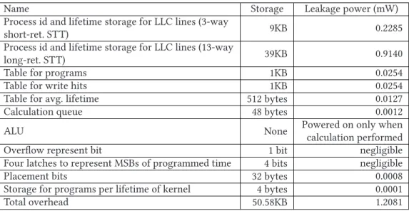
Hardware overheads. We should consider area and power overhead for additional storage.
The overhead of the MH cache is summarized in Table2. In our experiments using NVSim [11], the area of 1MB STT-RAM is 0.284mm2. In conclusion, to total area overhead (50.58KB) of MH
cache is approximately 0.014mm2, which is 1.1% and 4.9% of 1MB SRAM (measured by CACTI
[34]) and STT-RAM, respectively. Except for the additional LLC storage for the process id and lifetime, the total required storage size is 2,610 bytes. Short-retention STT-RAMs are appropriate for this additional storage, because these storages are very small, and therefore, the leakage and refresh energy consumptions of these storage are not large. These storages are frequently written in the low write dynamic energy of the short-retention STT-RAM cells. The write dynamic energy overhead cannot change the overall trends, because very small data are written (a total of 10 bytes and one bit; two bytes to store programmed timing in a cache line, one byte to store process id in a cache line, four bytes to store the number of programs; cache misses or write hits of each process, three bytes for calculation queue). When ALU is powered on, one bit for placement information is written but it is negligible. We measure the area of 32-bit ALU and multiplier/divider introduced from Reference [36] using Synopsys Design Compiler [46]. Because arithmetic operations required in MH cache are performed when a cache miss occurs, high-performance multiplier/dividier is not needed. And thus, we utilize multiplier/divider from Reference [36] to reduce area overhead. The area of additional ALU and multiplier/divider is approximately 0.0004mm2. It means the area of
additional ALU and multiplier/divider components are negligible compared to total LLC area. We considered all of these dynamic and leakage overheads, as shown in Figures15and17.
4 EVALUATION
4.1 Experimental Setup
We used gem5 [6], a cycle-accurate simulator, which supports the Android full system simulation. Table3 shows the system configuration. In our experimental environment, the L2 cache is the
MH Cache 26:17 Table 3. System Configuration
Core
2GHz single-/quad-cores
11 stage integer pipeline with 3-way decode 4-way out-of-order superscalar
L1 caches
Cache line size: 64B
16KB (I-Cache) +16KB (D-Cache) 4-way set associative, 2 cycles, 4MSHRs L2 cache Cache line size: 64B
1MB, 16-way set associative, 16MSHRs DRAM LPDDR2E 533MHz, single-channel, 32-bit
Table 4. Power and Energy Model
LLC. The power and energy model is summarized in Table4. We have three LLC configurations for the MH cache. The first configuration is a 2-way short- (128KB) and 14-way long-retention (896KB) STT-RAM part. The second configuration is a 3-way short- (192KB) and 13-way long-retention (832KB) STT-RAM part. The last configuration is a 4-way short- (256KB) and 12-way long-retention (768KB) STT-RAM part. We also experiment 1MB SRAM and 1MB STT-RAM. 1MB STT-RAM is used as a baseline in this article. The DRAM controller built into the gem5 is used to simulate the DRAM behavior with DRAMPower [8]. All cache power models are derived and referenced from Reference [52]. The STT-RAM model of Reference [52] is measured by NVSim [11]. We refer to Reference [45] to validate short-retention STT-RAM model of Reference [52]. The reason why the refresh interval(retention time) of short-retention STT-RAM is 3.24s is to fairly compare power consumption reduction of our scheme with EECD [51,52], which also use 3.24s of retention time for short-retention STT-RAM partition.
We increase the write dynamic energies of the short- and long-retention STT-RAMs of the MH cache to consider the overhead of additional data, which was discussed in the previous section. To integrate NoMali [9], we compiled Linux kernel and Android Kitkat image to install NoMali driver. We executed five benchmarks. Four benchmarks (adobe, BBench, frozenbubble, kingsoftoffice) are from the Moby benchmark suite [20] and the other benchmark (video) is an Android default video application. Because most of benchmarks in Moby [20] need user information (login id, password, user location, applications usage information, etc.), we selected four benchmarks from Moby that do not need user information. Many applications are installed in our experimental environment and they run in the background when benchmarks are running, similar to real mobile devices. In
Fig. 15. Average power breakdown of 1MB STT-RAM, 1MB short-retention STT-RAM, 8-way short- and 8-way long-retention STT-RAM cache with EECD [52], 2-way short- and 14-way long-retention STT-RAM, 3-way short- and 13-way long-retention, and 4-way short- and long-retention 12-way STT-RAM cache with MH cache in single-core experiments. All values are normalized to 1MB STT-RAM cache.
an Android system, the processes that do not affect the application running in the foreground are considered background processes [17,18]. ω, which is the weight of cache misses in PPL formula (Equation (3)) is determined as two, empirically, and multiplying by two can be calculated by a simple shift operation.
4.2 Power Consumption Results
Our experimental results are explained in this subsection. We will show the average power con-sumption, and the number of cache programs of the short-retention STT-RAM part and long-retention STT-RAM part of cache configurations used in our experiments for all five benchmarks on the hardware rendering system. We tested the single- and quad-core systems. We included the global cache miss rate and IPC to represent the performance impact of the MH cache.
4.2.1 Single-core Results. Figure15shows the average power breakdown of the 1MB SRAM, 1MB STT-RAM, 1MB short-retention STT-RAM, and EECD [52] with the same capacity, and our proposed scheme, MH cache, with 2-way short- and 14-way long-retention STT-RAM, 3-way short- and 13-way long-retention STT-RAM, and 4-way short- and 12-way long-retention STT-RAM. MH_S2_T14 means the MH cache configuration using 2-way short- and 14-way long-retention STT-RAM. In the single-core results, MH_S2_T14, MH_S3_T13, and MH_S4_T12 config-urations reduce by approximately 30.1%, 33%, and 32%, respectively, of cache power consumption on average compared to the 1MB STT-RAM cache. Compared to the EECD, our proposed scheme reduces approximately 12.9%, 15.7%, and 14.3%, respectively, of cache power consumption on aver-age. Compared to the 1MB short retention STT-RAM, our proposed scheme reduces 12.8%, 15.5%, and 14.2%, respectively, of cache power consumption on average. Regarding frozenbubble, the PPL rank of the kernel is 34, 77, and 105, when MH_S2_T14, MH_S3_T13, and MH_S4_T12 are used, respectively. Figure16shows the number of cache programs of short- and long- retention STT-RAM in the single-core experiments. As we can see in, MH_S4_T12 shows the lowest number of long-retention STT-RAM programs, which are the most important factor of dynamic power consumption. Most of cache programs are migrated to short-retention STT-RAM, and thus, the number of cache programs in short-retention STT-RAM of MH_S4_T12 is larger than other con-figurations. However, it does not show the best power reduction compared to other configurations because of short-retention STT-RAM leakage and dynamic power. However, considering perfor-mance impact, MH_S4_T12 is the most energy optimal configuration. This will be covered in the performance results section. When the number of short-retention STT-RAM ways is increased, the PPL of kernel is decreased, because only kernel utilize short-retention STT-RAM area at the first cache placement. In this case, because of decreased long-retention STT-RAM ways, the other
MH Cache 26:19
Fig. 16. The number of cache programs in short- (left) and long-retention (right) STT-RAM of EECD [52], and three configurations of MH cache in single-core experiments.
Fig. 17. Average power breakdown of 1MB STT-RAM, 1MB short-retention STT-RAM, 8-way short- and 8-way long-retnetion STT-RAM cache with EECD [52], 2-way and 14-way long-retention, 3-way short-and 13-way long-retention, short-and 4-way short- short-and 12-way long-retention STT-RAM cache with MH cache in quad-core experiments. All values are normalized to 1MB STT-RAM cache.
processes’ PPL increase than other configurations. Thus, in conclusion, almost frequently accessed processes are placed to short-retention STT-RAM, when the number of short-retention STT-RAM ways is increased in MH cache.
4.2.2 Multi-core Results. We experimented a quad-core system to verify our proposed scheme.
Figure17shows the average power breakdown of our experiments. All configurations are the same with single-core experiments. In the quad-core results, MH_S2_T14, MH_S3_T13, and MH_S4_T12 configurations reduce approximately 28.9%, 31.5%, and 32.2%, respectively, of cache power con-sumption on average compared to the 1MB STT-RAM cache. Compared to the EECD, MH cache with the same configurations reduce approximately 29.7%, 32.3%, and 33.1%, respectively, of cache power consumption on average. Compared to the 1MB short retention STT-RAM, our proposed scheme reduces 12.1%, 15.3%, and 16.2%, respectively, of cache power consumption on average. Unlike single-core experiments, EECD does not reduce power consumption compared to 1MB STT-RAM, because EECD did not consider hardware rendering and multi-core system. Figure18
shows the number of cache programs of short- and long-retention STT-RAM in the quad-core experiments. Regarding frozenbubble, the PPL rank of kernel is 12, 35, and 56, when MH_S2_T14, MH_S3_T13, and MH_S4_T12 are used, respectively. In overall, the PPL ranks of kernel are higher than single-core experiments. Because kernel runs in all cores and our LLC is shared LLC,
ker-nel is frequently programmed compared to single-core system. Especially, the PPL rank of kerker-nel
in BBench is 6, when MH_S2_T14 is used. It means only six processes can access short-retention STT-RAM area. In other configurations, MH_S3_T13 and MH_S4_T12, the PPL ranks of kernel in
Fig. 18. The number of cache programs in short- (left) and long-retention (right) STT-RAM of EECD, and three configurations of MH cache in quad-core experiments.
Fig. 19. IPC results on single- (left) and quad-core (right) systems. All values are normalized to STT-RAM baseline.
4.3 Performance Results
Figure19shows IPC results. The left figure shows the IPC of STT-RAM, EECD, and our proposed MH cache, in case of single-core system. The right one shows the IPC result of quad-core system. All values are normalized to the STT-RAM baseline. In the single-core experiments, our three configurations using MH cache present an average of 0.5%, 3% lower, and 10% higher IPC, compared to an STT-RAM cache. In the quad-core experiments, the MH cache shows 14%, 11% lower and 12% higher IPC, as compared to STT-RAM. Considering both IPC and power consumption, MH_S4_T12 provides the lowest energy consumption in this article. Because of reduced write latency of short-retention STT-RAM partition and many cache programs are operated in short-short-retention STT-RAM partition as shown in Figures16and18, performance of our proposed MH cache can be improved compared to STT-RAM baseline.
5 DISCUSSION
5.1 Short-Retention STT-RAM-based LLC
Although a short-retention STT-RAM-based LLC is a good candidate for energy-efficient LLC design, we explored a multi-retention STT-RAM-based LLC in this article. In our evaluations, a short-retention STT-RAM-based LLC presents average 20.7% and 19.1% lower power consump-tion in single- and quad-core experiments, respectively, compared to a convenconsump-tional STT-RAM-based LLC. Compared to a 1MB of short-retention STT-RAM-STT-RAM-based LLC, our proposed MH cache presents lower power consumption by 15.5% and 16.3% in the single- and quad-core experiments, respectively.
One may argue that the power consumption of short-retention STT-RAM-based LLCs can further be reduced with even shorter retention-time of the cells. However, it is still unclear that further reductions in retention time is beneficial. It has been reported that overly reduced cell retention time in STT-RAMs can cause reliability issues [25], because the cells may suffer from low thermal stability. Regarding extremely short retention-time STT-RAM-based LLCs, the work in
MH Cache 26:21
Fig. 20. Power consumption results with 8MB L2 cache and LPDDR3 single-core system.
Fig. 21. Power consumption results with 8MB L2 cache and LPDDR3 quad-core system.
Fig. 22. Power consumption results with 8MB L2 cache and LPDDR3 considering core power consumption in single-core system.
Reference [10] reports that strong error correction techniques are required. The work in Ref-erence [25] exploits periodic a scrubbing technique to deal with the problem. One limitation of the works including EECD [42,45,51,52] is that they do not provide detailed discussions about the issues and focus on the reduced write dynamic energy of short-retention STT-RAM. There-fore, MH cache utilizes short-retention STT-RAM of a small size, because only short-retention STT-RAM-based LLCs may cause reliability issues.
5.2 Experimental Results Using a Larger LLC
Our evaluation provides results using an LLC of 1MB to fairly compare our proposed scheme to EECD [51,52]. However, modern mobile processors have larger LLCs than 1MB. For instance, Ap-ple A12 has an 8MB L2 cache [4]. In this subsection, we present our experimental results using an 8MB L2 cache and LPDDR3 DRAM. Figures20and21describe the power consumption of the LLCs in single/quad-core experiments, respectively. A noteworthy difference is that the 8MB L2 cache has a relatively lower global miss rate. The STT-RAM, MH_S2_T14, MH_S3_T13, and MH_S4_T12 show 1.4%, 1.59%, 1.66%, and 0.72% of global cache miss rate reduction, respectively, as compared to
Fig. 23. Power consumption results with 8MB L2 cache and LPDDR3 considering core power consumption in quad-core system.
Fig. 24. IPC results of other thresholds on single- (left) and quad-core (right) systems. All values are normal-ized to MH_kernel.
the 1MB L2 cache. The 1MB L2 cache and 8MB L2 cache show similar power consumption trends, except for their cache miss rates. As compared to the STT-RAM, our MH_S2_T14, MH_S3_T13, and MH_S4_T12 reduce the power consumption by 26.1%, 25%, and 21.9%, respectively, in the single-core system. Whereas, in the quad-single-core system, our MH_S2_T14, MH_S3_T13, and MH_S4_T12 reduces the power consumption by 26.5%, 25.5%, and 28.3%, respectively.
5.3 Considering Total Chip Power Consumption
We measured the core power consumption using McPAT [32]. To make input file of McPAT, we made a gem5 output file to the McPAT input file with gem5-mcpat-parser [5] and a tool presented by MofySim [22]. We first measured the chip power consumption with 1MB L2 cache on single and quad-core systems. In SRAM, the core power consumption occupies approximately 62.2% of the total chip power consumption. However, in STT-RAM, the core power consumption is 90.7% of total chip power consumption. In this case, our proposed scheme only reduces approximately 5.3% of the total chip power consumption in the best-case scenario, as compared to the STT-RAM. This is owing to the small size of the L2 cache, as discussed in Section5.2. Thus, we also measured the total chip power consumption with the 8MB L2 cache. The results are shown in Figure23 (single-core) and Figure24(quad-core). In comparison to the STT-RAM, our MH_S2_T14, MH_S3_T13, and MH_S4_T12 reduce the power consumption by 5.3%, 11.6%, and 10.1%, respectively, in single-core system,. Whereas, in quad-core system, our MH_S2_T14, MH_S3_T13, and MH_S4_T12 reduce the power consumption by 6%, 6.7%, and 2.9%, respectively. Because power consumption of core is dominant when core is considered, the overall power consumption reduction of MH cache in quad-core system is much smaller than that of single-core system.
5.4 Hybrid Cache with SRAM/STT-RAM
We experimented with SRAM/STT-RAM hybrid cache, which uses SRAM instead of short-retention STT-RAM in our proposed scheme. However, it does not show any power consumption
MH Cache 26:23
Fig. 25. Power consumption results of other thresholds on single- (left) and quad-core (right) systems. All values are normalized to MH_kernel.
reduction, because the SRAM model presented in EECD [51,52], also used in our experiment, consumes a large amount of power. In comparison to the STT-RAM, if we apply the SRAM power model from EECD, our proposed scheme increases the power consumption by 48%, 78%, and 108%, respectively, in single-core system. We also measured cache power consumption with SRAM power model presented in Reference [22], which is validated in real devices. In these results, our proposed MH cache reduces the power consumption by 6%, 2.8%, and−0.3%, respectively, as compared to the STT-RAM cache, in the single-core system. In quad-core system, our proposed MH cache re-duces the power consumption by 10.2%, 7.8%, and 6.7%, respectively, as compared to the STT-RAM cache.
5.5 Substituting Variable Threshold with Other Processes
We analyzed the memory access behavior of variable processes in Sections 3.2 and 3.3. In Section3.3.1, we designated the PPL of the kernel as a variable threshold to classify data location. We experimented with the cases in which other processes are used as a classification criterion. Figure24shows performance results (IPC) when the PPL of other processes is used as a variable threshold. The PPL rank of kernel is approximately 60 for all processes, as shown in Table1. We experimented with processes that have a PPL rank of 30 (surfaceflinger), and those with rank 130 (android.io), considering them the variable threshold. In this experiment, MH_S3_T13 configu-ration is used. MH_android is the MH cache whose variable threshold is the PPL of android.io. MH_surface is the MH cache whose variable threshold is the PPL of surfaceflinger.
In these experiments, MH_android barely accesses the long-retention STT-RAM partition. This directly affects the system performance. In single- and quad-core results, MH_android shows 4.3% and 10.6% lower IPC, compared to MH_kernel, respectively. MH_surface also shows lower IPC, because cache blocks of kernel, which shows many memory operations as discussed in Section3, are placed in long-retention STT-RAM partition. In single- and quad-core results, MH_surface shows 3% and 13.3% lower IPC, compared to MH_kernel, respectively. Figure25shows power con-sumption results. On average, MH_android consumes 7% and 15.8% less power than MH_kernel in single- and quad-core system. MH_surface consumes 6% more and 2.9% less power than MH_kernel in single- and quad-core system. In conclusion, MH_android shows lower performance and improved power saving compared to MH_kernel. Deciding which process is used as a thresh-old can be a selective option. If an architect wants to reduce more power consumption by sacrificing performance, then a lower PPL rank process should be selected. Otherwise, if an architect wants to preserve the system performance, then a higher PPL rank process should be selected.
Regarding the placement threshold, we selected the kernel process as the criterion for the fol-lowing reasons. First, a fixed value for the placement threshold can be very inefficient. When the threshold value is fixed, the cache block placement decision becomes overly dependent on the currently running processes. Because the processes can have significantly different absolute PPL
6 CONCLUSION
Power consumption becomes more important as mobile systems become increasingly popular. Herein, we proposed a non-volatile memory-based energy-efficient multi-retention cache for mo-bile systems for hardware rendering devices. We observed process behaviors and created a new metric to manage the multi-retention cache: programs per lifetime (PPL), which measures write-intensity of a process dynamically. We classify processes by using PPL to determine cache line placement. In our experimental results, memory pollution caused by software rendering did not oc-cur, because we experiment on hardware rendering to mimic a realistic environment. Our scheme reduces 32% and 32.2% of cache power consumption in single-core and quad-core systems, respec-tively, compared to the full STT-RAM cache.
REFERENCES
[1] Junwhan Ahn, Sungjoo Yoo, and Kiyoung Choi. 2014. DASCA: Dead write prediction assisted STT-RAM cache architecture. In Proceedings of the IEEE 20th International Symposium on High Performance Computer Architecture (HPCA’14). IEEE, 25–36.
[2] David H. Albonesi. 1999. Selective cache ways: On-demand cache resource allocation. In Proceedings of the 32nd Annual International Symposium on Microarchitecture (MICRO’99). IEEE, 248–259.
[3] William Wang, Andreas Sandberg, and Stephan Diestelhorst. 2017. Architectural exploration with gem5. Tutor ASP-LOS (2017).
[4] Apple. 2018. Apple A12. Retrieved fromhttps://en.wikipedia.org/wiki/Apple_A12.
[5] Ayymoose. 2019. gem5-mcpat-parser. Retrieved fromhttps://github.com/Ayymoose/gem5-mcpat-parser.
[6] Nathan Binkert, Bradford Beckmann, Gabriel Black, Steven K. Reinhardt, Ali Saidi, Arkaprava Basu, Joel Hestness, Derek R. Hower, Tushar Krishna, Somayeh Sardashti et al. 2011. The gem5 simulator. ACM SIGARCH Comput. Archi-tect. News 39, 2 (2011), 1–7.
[7] Aaron Carroll, Gernot Heiser et al. 2010. An analysis of power consumption in a smartphone. In Proceedings of the USENIX Annual Technical Conference, vol. 14. 21–21.
[8] Karthik Chandrasekar, Christian Weis, Yonghui Li, Benny Akesson, Norbert Wehn, and Kees Goossens. 2012. DRAM-Power: Open-source DRAM power & energy estimation tool. Retrieved fromhttp://www. drampower. info. [9] Rene De Jong and Andreas Sandberg. 2016. NoMali: Simulating a realistic graphics driver stack using a stub GPU. In
Proceedings of the IEEE International Symposium on Performance Analysis of Systems and Software (ISPASS’16). IEEE, 255–262.
[10] Brandon Del Bel, Jongyeon Kim, Chris H. Kim, and Sachin S. Sapatnekar. 2014. Improving STT-MRAM density through multibit error correction. In Proceedings of the Conference on Design, Automation & Test in Europe. Euro-pean Design and Automation Association, 182.
[11] Xiangyu Dong, Cong Xu, Norm Jouppi, and Yuan Xie. 2014. NVSim: A circuit-level performance, energy, and area model for emerging non-volatile memory. In Emerging Memory Technologies. Springer, 15–50.
[12] Hamed Farbeh, Hyeonggyu Kim, Seyed Ghassem Miremadi, and Soontae Kim. 2016. Floating-ECC: Dynamic reposi-tioning of error correcting code bits for extending the lifetime of STT-RAM caches. IEEE Trans. Comput. 65, 12 (2016), 3661–3675.
[13] Bhavishya Goel and Sally A. McKee. 2016. A methodology for modeling dynamic and static power consumption for multicore processors. In Proceedings of the IEEE International Parallel and Distributed Processing Symposium. IEEE, 273–282.
[14] Google. 2011. Android Ice Cream Sandwich. Retrieved fromhttps://developer.android.com/about/versions/android-4. 0-highlights.
[15] Google. 2011. Hardware acceleration. Retrieved from https://developer.android.com/guide/topics/graphics/ hardware-accel.
[16] Google. 2013. Android Kitkat. Retrieved fromhttps://www.android.com/versions/kit-kat-4-4/.
MH Cache 26:25 [18] Google. 2019. Limited background behavior. Retrieved fromhttps://developer.android.com/about/versions/oreo/
background.
[19] Anthony Gutierrez, Ronald G. Dreslinski, Thomas F. Wenisch, Trevor Mudge, Ali Saidi, Chris Emmons, and Nigel Paver. 2011. Full-system analysis and characterization of interactive smartphone applications. In Proceedings of the IEEE International Symposium on Workload Characterization (IISWC’11). IEEE, 81–90.
[20] Yongbing Huang, Zhongbin Zha, Mingyu Chen, and Lixin Zhang. 2014. Moby: A mobile benchmark suite for ar-chitectural simulators. In Proceedings of the IEEE International Symposium on Performance Analysis of Systems and Software (ISPASS’14). IEEE, 45–54.
[21] Aamer Jaleel. 2018. Memory Characterization of Workloads Using Instrumentation-Driven Simulation. Retrieved fromhttp://www.jaleels.org/ajaleel/publications/SPECanalysis.pdf.
[22] Minho Ju, Hyeonggyu Kim, and Soontae Kim. 2016. MofySim: A mobile full-system simulation framework for energy consumption and performance analysis. In Proceedings of the IEEE International Symposium on Performance Analysis of Systems and Software (ISPASS’16). IEEE, 245–254.
[23] Samira Khan, Alaa R. Alameldeen, Chris Wilkerson, Onur Mutluy, and Daniel A. Jimenezz. 2014. Improving cache performance using read-write partitioning. In Proceedings of the IEEE 20th International Symposium on High Perfor-mance Computer Architecture (HPCA’14). IEEE, 452–463.
[24] Hyeonggyu Kim, Soontae Kim, and Jooheung Lee. 2017. Write-amount-aware management policies for STT-RAM caches. IEEE Trans. Very Large Scale Integr. Syst. 25, 4 (2017), 1588–1592.
[25] Namhyung Kim and Kiyoung Choi. 2016. Exploration of trade-offs in the design of volatile STT–RAM cache. J. Syst. Architect. 71 (2016), 23–31.
[26] Emre Kültürsay, Mahmut Kandemir, Anand Sivasubramaniam, and Onur Mutlu. 2013. Evaluating STT-RAM as an energy-efficient main memory alternative. In Proceedings of the IEEE International Symposium on Performance Analysis of Systems and Software (ISPASS’13). IEEE, 256–267.
[27] Benjamin C. Lee, Engin Ipek, Onur Mutlu, and Doug Burger. 2009. Architecting phase change memory as a scalable dram alternative. In ACM SIGARCH Computer Architecture News, vol. 37. ACM, 2–13.
[28] Benjamin C. Lee, Ping Zhou, Jun Yang, Youtao Zhang, Bo Zhao, Engin Ipek, Onur Mutlu, and Doug Burger. 2010. Phase-change technology and the future of main memory. IEEE Micro 30, 1 (2010).
[29] Kangho Lee and Seung H. Kang. 2011. Development of embedded STT-MRAM for mobile system-on-chips. IEEE Trans. Magnet. 47, 1 (2011), 131–136.
[30] Jianhua Li, Liang Shi, Qing’an Li, Chun Jason Xue, Yiran Chen, and Yinlong Xu. 2013. Cache coherence enabled adaptive refresh for volatile STT-RAM. In Proceedings of the Conference on Design, Automation and Test in Europe. EDA Consortium, 1247–1250.
[31] Qingan Li, Yanxiang He, Jianhua Li, Liang Shi, Yiran Chen, and Chun Jason Xue. 2015. Compiler-assisted refresh minimization for volatile STT-RAM cache. IEEE Trans. Comput. 64, 8 (2015), 2169–2181.
[32] Sheng Li, Jung Ho Ahn, Richard D. Strong, Jay B. Brockman, Dean M. Tullsen, and Norman P. Jouppi. 2009. McPAT: An integrated power, area, and timing modeling framework for multicore and manycore architectures. In Proceedings of the 42nd Annual IEEE/ACM International Symposium on Microarchitecture (MICRO’09). IEEE, 469–480.
[33] Sparsh Mittal, Jeffrey S. Vetter, and Dong Li. 2014. A survey of architectural approaches for managing embedded DRAM and non-volatile on-chip caches. IEEE Trans. Parallel Distributed Syst. 26, 6 (2014), 1524–1537.
[34] Naveen Muralimanohar, Rajeev Balasubramonian, and Norman P. Jouppi. 2009. CACTI 6.0: A tool to model large caches. HP Lab. (2009), 22–31.
[35] Sang Phill Park, Sumeet Gupta, Niladri Mojumder, Anand Raghunathan, and Kaushik Roy. 2012. Future cache design using STT MRAMs for improved energy efficiency: Devices, circuits and architecture. In Proceedings of the 49th Annual Design Automation Conference. ACM, 492–497.
[36] David A. Patterson and John L. Hennessy. 2008. Computer Organization and Design, 4th ed. Morgan Kaufmann, 230– 241.
[37] Muhammad Avais Qureshi, Hyeonggyu Kim, and Soontae Kim. 2019. A restore-free mode for MLC STT-RAM caches. IEEE Trans. Very Large Scale Integr. Syst. 27, 6 (2019), 1465–1469.
[38] Moinuddin K. Qureshi, Michele M. Franceschini, and Luis A. Lastras-Montano. 2010. Improving read performance of phase change memories via write cancellation and write pausing. In Proceedings of the IEEE 16th International Symposium on High Performance Computer Architecture (HPCA’10). IEEE, 1–11.
[39] Moinuddin K. Qureshi, Aamer Jaleel, Yale N. Patt, Simon C. Steely, and Joel Emer. 2007. Adaptive insertion policies for high performance caching. In ACM SIGARCH Computer Architecture News, vol. 35. ACM, 381–391.
[40] Moinuddin K. Qureshi, Vijayalakshmi Srinivasan, and Jude A. Rivers. 2009. Scalable high performance main memory system using phase-change memory technology. ACM SIGARCH Comput. Architect. News 37, 3 (2009), 24–33. [41] Samsung. 2019. Galaxy S9 and S9+ Specificaions. Retrieved from https://www.samsung.com/us/smartphones/
![Fig. 1. Related works and our proposed MH cache. (a) Introduces hybrid cache with various memory cells [ 50 ]](https://thumb-ap.123doks.com/thumbv2/123dokinfo/5095516.77813/5.729.78.656.121.262/related-works-proposed-cache-introduces-hybrid-various-memory.webp)
![Fig. 2. L2 cache access percentage observation from References [ 51 , 52 ]. This observation is quite different from ours](https://thumb-ap.123doks.com/thumbv2/123dokinfo/5095516.77813/6.729.164.564.146.314/cache-access-percentage-observation-references-observation-quite-different.webp)
![Fig. 4. Relative error rates compared to real GPU [ 3 ].](https://thumb-ap.123doks.com/thumbv2/123dokinfo/5095516.77813/7.729.163.567.473.614/fig-relative-error-rates-compared-to-real-gpu.webp)