1. INTRODUCTION
Central pattern generators (CPGs) in the nervous system of humans or animals produce rhythmic patterned outputs to cause the legs to walk adapting to the natural frequency of their body dynamics. This can also be realized within mechanical systems by mathematically modeling CPGs and incorporating them into an artificial neural oscillator network. The mathematical description of the artificial neural oscillator was addressed in detail in Matsuoka’s works, where neurons were proven to generate the rhythmic patterned output [1] and the conditions necessary for the steady state oscillations were analyzed. He also investigated the mutual inhibition networks to control the frequency and pattern in the neural rhythm generator [2], but did not include the effect of the feedback on the neural oscillator. Whenever the sensory signal is fed back into the neural oscillator, the neural oscillator network can perceive and adapt to the changes in the outer condition. This adaptation enables to embody the nervous and musculoskeletal systems of an animal in the mechanical system. Specifically, the entrainment process of the neural oscillator plays a key role to adapt the nervous system to the natural frequency of the human body. The neural oscillator, as a reactive controller, is dependent upon the interaction with the environment to create complicated and adaptive behavior without requiring any explicit models of the controller or the environment. Thus, if the artificial neural oscillator is coupled to control systems dynamics, this biologically inspired control system can be widely applied to unstructured real-world environments.
Employing the Matsuoka neural oscillator (MNO), Taga et
al. investigated a task with more reasonable complexities [3].
The sensory signals from the biped robot joint angles were used as the feedback signals to be entrained with the MNO [4]. As a result, the robot became robust to the perturbation and could walk up the slope [5]. This bipedal robot walking was simulated and applied to the 3D locomotion by Miyakoshi et
al. [6]. Based on theses works, the MNO implemented a
dynamic quadrupedal walking [7]. Williamson [8], [9] developed the neuro-mechanical system, where the artificial neural oscillator was coupled to the physical arm, and applied it to the robot arm control. Most of the previous works on the MNO, the entrainment function was exploited only to reproduce the frequency of the sensory signal. In other words, the existing neural oscillator can not entrain the shape and
amplitude of the input signal completely and thus the possible application fields are quite limited.
In this work, we propose the entrainment-enhanced neural oscillator (EENO). In order to make the EENO easily adaptable for a wide variety of the input signals, such as quasi-periodic or non-periodic inputs, a new control term is added in the well-known equation of the MNO. The EENO can be effectively used in the skill learning by goal-directed imitation between dissimilar bodies requiring redesign of the perceived demonstrated behaviors [10]. This paper deals with a simple mechanical system model coupled to the neural oscillator and discuss the difference of dynamic response between the MNO and EENO-activated systems. In the following section, we briefly describe the MNO and the EENO. In Section III, we address the difference of the entrainment properties with simulation results. Details of dynamic responses of both models are discussed in Section IV and conclusions are drawn in Section V.
2. THE NEURAL OSCILLATOR NETWORK
The basic motor pattern generated by a CPG is usually modified by sensory signal from motor information to deal with environmental disturbances. Similarly, artificial neural oscillators are entrained with external stimuli at a sustained frequency. They show stability against perturbations through global entrainment between the neuro-musculo-skeletal systems and the environment [4]. Thus, neural oscillators have been applied to CPGs of humanoid robots with rhythmic motions [11], [12]. This section addresses the mathematical descriptions of the MNO and the EENO.2.1 MNO model
The MNO consists of two simulated neurons arranged in mutual inhibition as shown in Fig. 1 [1], [2]. If gains are properly tuned, the system exhibits limit cycle behavior. The trajectory of a stable limit cycle can be derived analytically and describes the firing rate of a neuron with self-inhibition. The MNO is represented by a set of nonlinear coupled differential equations given by
Dynamic Systems Control Using Entrainment-enhanced Neural Oscillator
Woosung Yang and Nak Young Chong
School of Information Science, Japan Advanced Institute of Science and Technology, Ishikawa 923-1292, Japan (Tel : +81-761-51-1248; E-mail: {woo-yang, nakyoung}@jaist.ac.jp)
Abstract: In this paper, an approach to dynamic systems control is addressed based on exploiting the potential features of the new
nonlinear neural oscillator. Neural oscillators have recently enabled robots to exhibit natural dynamics using their robustness and entrainment properties. To technically accomplish this objective, the neural oscillator should be connected to the robot joints under the sensory feedback. This also requires the neural oscillator to adapt to the non-periodic nature of arbitrary input patterns. However, even in the most widely-used Matsuoka oscillator, when an unknown quasi-periodic or non-periodic signal is applied, its output signal is not always closely entrained. Therefore, current neural oscillators may not be applied to the precise control of the dynamic systems response. We illustrate the enhanced entrainment properties of the new neural oscillator by numerical simulation and show the possibility for implementation to control a variety of dynamic systems. It is verified that the oscillator can produce rhythmic signals for generating actuator signals which can be naturally modified by incorporating sensory feedback to adapt to outer circumstances.
(1)
where xe(f)i is the inner state of the i-th neuron which represents
the firing rate; ve(f)i is a variable which represents the degree of
the adaptation, modulated by the adaptation constant b, or self-inhibition effect of the i-th neuron; the output of each neuron ye(f)i is taken as the positive part of xi, and the output of
the whole oscillator as Y(out)i; wijyi represents the total input
from the neurons inside a neural network; the input is arranged to excite one neuron and inhibit the other, by applying the positive part to one neuron and the negative part to the other; the inputs are scaled by the gains ki; Tr and Ta are time
constants of the inner state and the adaptation effect of the i-th neuron respectively; b is a coefficient of the adaptation effect; wij is a connecting weight from the j-th neuron to the
i-th neuron; si is an external input with a constant rate.
Especially, wij (0 for i≠j and 1 for i=j) is a weight of inhibitory
synaptic connection from the j-th neuron to the i-th, and wei,
wfi are also a weight from extensor neuron to flexor neuron,
respectively.
Eq. (1) can be rearranged as follows:
Based on Eq. (2), we can design the output pattern.
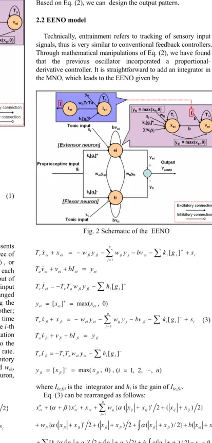
2.2 EENO model
Technically, entrainment refers to tracking of sensory input signals, thus is very similar to conventional feedback controllers. Through mathematical manipulations of Eq. (2), we have found that the previous oscillator incorporated a proportional- derivative controller. It is straightforward to add an integrator in the MNO, which leads to the EENO given by
(3)
where I(e,f)i is the integrator and hi is the gain of I(e,f)i.
Eq. (3) can be rearranged as follows:
(4) Fig. 2 Schematic of the EENO
Fig. 1 Schematic of the MNO
) , , 2 , 1 (i = ⋅⋅⋅ n ei ei ei av v y T& + = ) 0 , max( ] [ ei ei ei x x y = + =
∑
∑
− − + − − = + − = i i i n j fi j ij ei ei fi fi rx x w y wy bv k g s T [ ] 1 & fi fi fi av v y T& + = , ) 0 , max( ] [ fi fi fi x x y = + =∑
∑
− − + − − = + + = i i i n j ij j ei fi fi ei ei rx x w y w y bv k g s T [ ] 1 & ei ei ei ei av v bI y T & + + = ) 0 , max( ] [ ei ei ei x x y = + =∑
∑
− − + − − = + − = i i i n j fi j ij ei ei fi fi rx x w y w y bv k g s T [ ] 1 & fi fi fi fi av v bI y T & + + = ) , , 2 , 1 (i = ⋅⋅⋅ n , ) 0 , max( ] [ fi fi fi x x y = + =∑
∑
− − + − − = + + = i i i n j ei j ij fi fi ei ei rx x w y w y bv k g s T [ ] 1 &∑
+ − − = r a fi fi i[ i] ei rI TT w y h g T &∑
− − − = r a ei ei i[ i] fi rI TT w y h g T∑
= + + ′ + + + ′ + + ′′ n j ij ij ij ij ij ei ei ei x x w x x x x x 1 } 2 ) ( 2 ) ( { ) (α β α 2 ) ( } 2 / ) ( 2 ) ( 2 ) ( { fi fi fi fi fi fi ei ei fi x x x x x x b x x w + ′ + + + + + + + α∫
α∑
+ ′ + + +∫
+ − = + [ki{α(gi gi) 2 (gi gi) 2} hi γ(gi gi)/2] si 0∑
= + + ′ + + + ′ + + ′′ n j ij ij ij ij ij fi fi fi x x w x x x x x 1 } 2 ) ( 2 ) ( { ) (α β α ) 1 , , , (τ=t TaTr α=Ta TaTr β=Tr TaTr γ= Tr TaTr 2 ) ( } 2 / ) ( 2 ) ( 2 ) ( { ei ei ei ei ei ei fi fi ei x x x x x x b x x w + ′ + + + + + + + α∫
α∑
− ′ + − +∫
− − = − [ki{α(gi gi) 2 (gi gi) 2} hi γ(gi gi)/2] si 0∑
+ ′ + + + + ′ + + ′′ ( ) ei ei ij{ ( ij ij) 2 ( ij ij) 2} ei x x w x x x x x α β α i ei ei fi fi fi fi fi x x x x b x x s w + ′ + + + + − + {α( ) 2 ( ) 2} ( ) 2∑
+ ′ + + = + ki{α(gi gi) 2 (gi gi) 2} 0∑
+ ′ + + + + ′ + + ′′ ( ) fi fi ij{ ( ij ij) 2 ( ij ij) 2} fi x x w x x x x x α β α i fi fi ei ei ei ei ei x x x x b x x s w + ′ + + + + − + {α( ) 2 ( ) 2} ( ) 2∑
− ′ + − = − ki{α(gi gi) 2 (gi gi) 2} 0 ) , , (τ=t TaTr α=Ta TaTr β=Tr TaTrSolving Eq. (4), we can design the output pattern.
3. THE ENTRAINMENT PROPERTY OF THE
NEURAL OSCILLATOR
The entrainment properties of the neural oscillators will be illustrated in this section. In order to apply the neural oscillators generating rhythmic signals to the dynamic systems control, we first have to investigate the condition necessary for the stable oscillation. Under this condition, the entrainment and input-output properties of the oscillators can be utilized for a variety of tasks with the same architecture, without any modeling of system or its environment [8], [9]. For the stable oscillation [1], [2], if tonic input exists, Tr/Ta should be in the
range of 0.1 to 0.5, for which the natural frequency of the oscillator is proportional to 1/Tr. Increasing the input gain, ki,
causes the output of neural oscillator to be entrained with the amplitude and natural frequency of the input signal.
3.1 Stable oscillated output
This subsection discusses the rhythmic patterned output generation by the MNO and the EENO. Figs. 3 and 4 show the output of the EENO in time domain and the Fast Fourier Transform (FFT) and the phase plane trajectory under a stable condition. Let Yi denote the total output and Yi1 and Yi2 denote
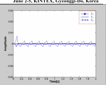
the extensor and the flexor output of both oscillators with a designated initial condition, respectively. When the initial positions of Y11, Y21, and Y31 are set to 0.8, 0.2 and -1.2,
respectively, Fig. 5 shows the output mismatch between the MNO and the EENO which can be considered negligible, if numerical errors are taken into account. Therefore we can verify that the EENO also produce rhythmic patterned output.
3.2 Evaluation of the entrainment properties
The entrainment properties of both neural oscillators are compared in this subsection. Figs. 6 and 7 are the output signals of the MNO and the EENO entrained by the sensory input signal, respectively. Even though the parameters are optimally tuned, the main limitation still exists in the MNO. If a quasi-periodic or a non-periodic input signal enters the MNO, the oscillator sometimes would not remain perfectly entrainable as shown in Fig. 6. In this case, Tr, Ta, and k were
set as 0.04, 0.08, and 0.6, respectively. On the other hand, if we employ the EENO with the newly induced integrator, the deviation from the input signal will disappear as shown in Fig. 7. It can be observed that the entrainment error decreases with time. From the results so far, the EENO has proven to be robust with respect to the inputs of non-periodicity.
Fig. 4 FFT and limit cycle for the output in Fig. 3 Fig. 3 Output of neural oscillator under a stable condition.
Fig. 6 Output signal of the MNO entrained by the input signal Fig. 5 Output mismatch between the MNO and the EENO
4. DYNAMIC RESPONSE OF MECHANICAL SYS
TEM MODEL
This section addresses an approach to dynamic systems control exploiting the natural dynamics of the neural oscillator coupled simple mechanical system interacting with the unknown environment. The system is adaptable to the environment, because the sensory signal from the joints of the system appropriately alters the frequency and phase of the oscillator output signals. Also the system is robust over a specific frequency range even if the environment is changed or unknown parameters exist [8], [9]. Moreover, the proposed EENO can alter not only the frequency and phase of the outputs, but also their amplitude, which is the main contribution of this work.
4.1 Mechanical system coupled to the neural oscillator
Fig. 8 illustrates a simple mechanical system model connected to the neural oscillator. As shown in Fig 8, the output of the neural oscillator drives the system corresponding to the sensory signal input (feedback) from the displacement or torque of the system joint. The input signal makes the output signal to be entrained. With this entrainment mechanism of the neural oscillator, the mechanical system can exhibit adaptive behavior under the unknown environment condition. The desired torque [8] input at the ith joints is
i i i vi i di k b u = (θ −θ)− θ&, (5) where ki is the stiffness of the joint, bi the damping coefficient,
θi the joint angle, and θvi the equilibrium point which is the
output of the neural oscillator.
4.2 Simulation results
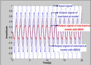
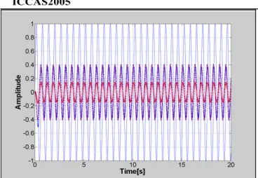
We simulated the dynamic response to a sinusoidal input to compare the entrainment properties of the MNO and the EENO. In Fig. 9, the thick dashed lines are the outputs of the models not coupled, coupled to the MNO, and coupled to the EENO, respectively. Even though the frequency and phase are well entrained, the output amplitude is not entrained in both the MNO and EENO models, if we compare them with the output of the model not coupled. Theoretically, since the output is returned to the oscillator as the sensory signal input, the output should be adapted to the input, especially with the EENO coupled model. Note that Figs. 10-12 show the good entrainment performance of the EENO coupled model, where the driving frequencies are 10, 15, and 20 rad/sec, respectively. Therefore, if the driving input frequency is far away from the natural frequency of the neural oscillator, it can not entrain the input signal with the same amplitude. We found that a proper range of frequencies exists to entrain the input signal completely even in the EENO coupled model. Therefore, one should carefully look into the range of possible frequencies to apply the EENO to the control of dynamic systems response.
Fig. 8 Mechanical system model with the neural oscillator.
Fig. 9 Dynamic response of the MNO and the EENO with a 5 rad/s sinusoidal input
5. CONCLUSION
This paper has embodied the entrainment behaviors of the humans or animals within the mechanical system employing the neural oscillator. For this, we proposed the entrainment -enhanced neural oscillator which enables precise dynamic response control of the mechanical system under unknown outer conditions. We clearly verified the basic characteristics of the proposed neural oscillator under the stable oscillation condition and its enhanced entrainment properties comparing
with the existing neural oscillator. Also, the dynamic response of the oscillator-coupled simple mechanical model was investigated. Specifically, the output signal of the proposed oscillator coupled system could be adapted to the frequency, phase, and amplitude of the sensory input signal over a reasonable frequency range. This approach will be the first step toward the realization of biologically inspired control architectures. Relating to the future research, we will verify the practical validity of this approach through experiments with more complicated mechanical systems.
ACKNOWLEDGMENTS
This research is conducted as a program for the "Fostering Talent in Emergent Research Fields" in Special Coordination Funds for Promoting Science and Technology by Ministry of Education, Culture, Sports, Science and Technology of Japan.
REFERENCES
[1] K. Matsuoka, “Sustained Oscillations Generated by Mutually Inhibiting Neurons with Adaptation”,
Biological Cybernetics, Vol. 52, pp. 367-376, 1985.
[2] K. Matsuoka, “Mechanisms of Frequency and Pattern Control in the Neural Rhythm Generators”, Biological
Cybernetics, Vol. 56, pp. 345-353, 1987.
[3] G. Taga, Y. Yamagushi and H. Shimizu, Self-organized control of bipedal locomotion by neural oscillators in unpredictable environment, Biological Cybernetics, Vol. 65, pp. 147-159, 1991.
[4] G. Taga, “A model of the neuro-musculo-skeletal system for human locomotion”, Biological Cybernetics, Vol. 73, pp. 97-111, 1995.
[5] O. Katayama, Y. Kurematsu and S. Kitamura, “Theoretical Studies on Neuro Oscillator for Application of Biped Locomotion”, Proc. IEEE Int.
Conf. on Robotics and Automation, Vol. 3, pp.
2871-2876,1995.
[6] S. Miyakoshi, G. Taga, Y. Kuniyoshi, and A. Nagakubo, “Three dimensional bipedal stepping motion using neural oscillators – towards humanoid motion in the real world, Proc. IEEE/RSJ Int. Conf. on Intelligent Robots
and Systems, Vol. 1, pp. 84-89, 1998.
[7] H. Kimura, K. Sakurama and S. Akiyama, “Dynamic walking and running of the quadruped using neural oscillators, Proc. IEEE/RSJ Int. Workshop on Intelligent
Robots and System, Vol. 1, pp. 50-57, 1998.
[8] M. M. Williamson, “Exploiting natural dynamics in robot control”, In Fourteenth European Meeting on
Cybernetics and Systems Research, 1998.
[9] M. M. Williamson, “Rhythmic Robot Arm Control Using Oscillators”, Proc. IEEE/RSJ Int. Conf. on
Intelligent Robots and Systems, 1998.
[10] W. Yang, N. Y. Chong, “Goal-directed Imitation with Self-adjusting Adaptor Based on a Neural Oscillator Network”, Proc. IEEE Int. Conf. on Advanced Robotics, 2005, accepted for presentation.
[11] O. Katayama, Y. Kurematsu and S. Kitamura, “Theoretical Studies on Neuro Oscillator for Application of Biped Locomotion”, Proc. IEEE Int.
Conf. on Robotics and Automation, Vol. 3, pp.
2871-2876, 1995.
[12] M. Ogino, Y. Katoh, M. Aono, M. Asada and K. Hosoda, “Reinforcement learning of humanoid rhythmic walking parameters based on visual information”, Advanced
Robotics, Vol. 18, No. 7, pp. 677-697, 2004.
Fig. 12 Dynamic response of the MNO and the EENO with a 20 rad/s sinusoidal input
Fig. 11 Dynamic response of the MNO and the EENO with a 15 rad/s sinusoidal input
Fig. 10 Dynamic response of the MNO and the EENO with a 10 rad/s sinusoidal input