서 론
전자선가속기는 고분자물질의 방사선화학 가교에 주로 이용되었으나 현재에 이르러서는 반도체 개발에서 오염된 물의 정화에 이르기까지 여러 분야에서 사용되고 있으며 응 용 범위도 점점 넓혀가고 있다(Ha et al. 2010). 국내에는 타 이어 가교, 전선, 건축용 내장재, 자동차 발포 내장재, 연구 용, 표면경화처리 등으로 사용되고 있으며 최근에는 5~10 MeV의 고에너지로 가속하여 살균, 멸균을 하는 상업용 가 속기로도 이용되고 있다(Lee 2009). 특히 의료산업 분야에 서 인체 내 발생한 종양에 방사선을 조사하여 치료하는 의 료용 선형가속기와 같은 치료기로 사용되기도 하며 인체에 덜 해롭고 선명도가 높은 X선 장치에도 사용되고 있고 전기·전자 산업 분야에서는 PWRTR(Pollutant Release and Transfer Register), IGBT(Insulted Gate Bipolar Transistor), Diode, MOSFET(Metal Oxide Semiconductor Field Effect
물질별 깊이선량분포 분석을 통한 전자선 투과깊이에 관한 연구
오세희1· 김신애2,3· 이윤종3· 정운관1,*
1조선대학교 원자력공학과, 2한양대학교 원자력공학과, 3한국원자력연구원 첨단방사선연구소
A Study on the Depth of Penetration Depth of Electron Beam
by Analysis of Depth-Dose Distribution by Material
Se-Hee Oh
1, Shin-Ae Kim
2,3, Yun-jong Lee
3and Won-Kwan Chung
1,*
1Nuclear Engineering, Chosun University, 309 Pilmun-daero, Dong-gu, Gwangju 61452, Republic of Korea 2Nuclear Engineering, Hanyang University, 222 Wangsimni-ro, Seongdong-gu, Seoul 04763,
Republic of Korea
3Korea Atomic Energy Research Institute(KAERI), 1266, Sinjeoung-dong, Jeongeup-si, Jeollabuk-do 56212, Republic of Korea
Abstract - As the range of operation of the accelerator expands, a wider variety of products and materials are being irradiated. However, the requirements for dosimetry depend on the irradiation process and on the characteristic of the product. In particular, since it is important to find an optimal depth of penetration compared to dosimetry requirement based on the material in the electron beam. Therefore, the objective of this study is to irradiate selected target materials under various dose conditions and to analyse the depth-dose distribution to derive optimal irradiation conditions for each substance. The contents of this study are as follows. Depth-dose distribution analysis by substance was conducted by selecting five substances, preparing them in a plate, stacking them together, attaching B3 film dosimeter, and examining them on electric beams. In order to derive optimal irradiation conditions for each substance, a single-sided irradiation and a double-sided irradiation were then conducted under various dose conditions and the relationship between depth-dose and density of the material was then analysed through the results of the experiment. Key words : Electron beam, Accelerator, B3 film dosimeter, Depth-dose distribution
─ 29 ─ Technical Paper
* Corresponding author: Woon-Kwan Chung, Tel. +82-62-230-7166, Fax. +82-62-232-9218, E-mail. [email protected]
Transistor) 등 전력 반도체 소자의 고속 스위칭을 통한 성능 향상에도 사용되고 있다(Kim 2007; Kim 2015). 또한 관리 가 쉽고 대용량 처리가 가능한 특징으로 인해 식품 포장재, 위생용품, 의료용품 등의 멸균시장 분야에서 사용되고 있다 (식품의약품안전청 2006). 가속기의 운용 범위가 넓어짐에 따라 보다 다양한 종류의 제품 및 재료가 조사되고 있다. 그러나 선량측정의 요건은 방사선 조사 과정과 제품의 특성에 따라 달라진다(National Physical Laboratory 2009). 특히 전자선은 감마선에 비해 투 과깊이가 낮아 적정깊이를 찾는 것이 중요하기 때문에 전자 선의 물질에 따른 선량측정 요건의 정립이 필요한 시점이다 (International Atomic Energy Agency 2005).
따라서 본 연구는 선정된 대상 물질을 전자선에 조사시 켜 깊이선량분포를 분석하여 물질별 최적의 조사조건을 도 출하는 것이 목적이다. 물질별 최적의 조사조건을 도출하기 위하여 총 5가지 물질을 선정한 후 단면조사 및 양면조사를 수행하였으며 B3 필름 선량계를 이용한 선량측정 결과를 통해 깊이선량과 물질의 밀도와의 관계를 분석하였다.
재료 및 방법
1. 깊이선량분포 측정 대상 깊이선량분포의 측정 대상물질은 물의 밀도를 기준으로 물 의 밀도보다 작은 밀도를 가진 물질과 큰 밀도를 가진 물질 중 대표적인 물질을 대상으로 선정하였다. 선정된 실험 대상 의 크기와 무게를 직접 측정하여 Table 1과 같이 규격 및 밀 도를 산출하였다(Omnexus The material selection platform 2019; Matweb Material property data 2019)(Table 1).2. 깊이선량분포 측정 방법 실험은 각 물질을 판 형태로 준비하여 적층을 쌓아 진행되 었다(Fig. 1). 적층은 동일한 크기와 두께를 가진 판자를 쌓 아 올리고 적층 중심을 따라 판과 판 사이에 B3 필름 선량계 를 배치하여 조사시킨 후 선량을 측정하는 방법이다(GEX Corporation USA 2010). 깊이선량분포 측정대상을 전자선 조 사 시 측정대상은 컨베이어 중앙에 위치되어야 하며 측정대 상을 고정하는 데 트레이나 작은 통 같은 용기가 사용되는 경 우 컨테이너 측면이나 벽에서 멀리 떨어져 있어야 한다. 또한 전자선 조사기와 측정대상 간의 거리는 통상적으로 운용되는 공정 동안의 전자선 조사기와 제품 간의 거리와 동일해야 하 며 측정대상은 방사 구역을 통해 컨베이어를 일정한 속도로 움직여 조사되어야 한다. 전자선의 입사각은 측정대상 표면에 수직이어야 한다(ISO/ASTM 2015).
결 과
1. 단면조사 1.1 물질별 깊이선량분포 물질별 단면조사 깊이선량분포 곡선의 동향을 알아보기Table 1. Measurement target of depth-dose distribution Polyethylene
(PE) Acrylic Polyethylene terephthalate(PET) Polyvinyl chloride(PVC) Aluminum Size[mm]
(W×D×H) 300×300×20 300×300×20 300×300×20 300×300×20 300×300×20
Density[g·cm-3] 0.9722 1.2056 1.2889 1.6111 2.6667
위하여 4가지 선량 조건(10kGy, 15kGy, 20kGy, 25kGy)에
서 조사시킨 후 그래프로 도식화하였다. PE의 선량별 깊이
선량분포는 표면선량율이 평균적으로 약 86% 정도로 나타
났으며 최대선량은 평균 약 21.5mm 두께에서 도달하였다
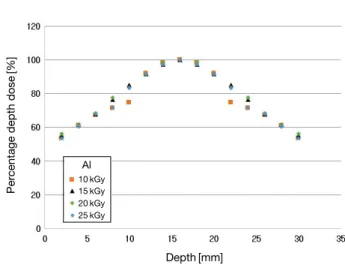
(Fig. 2). Acrylic은 표면선량율이 PE보다 조금 낮은 정도인 약 84%였고 최대선량은 약 23mm 정도에서 나타났다(Fig. 3). PET의 결과 역시 PE와 Acrylic과 유사하게 표면선량율 은 약 85% 정도였으나 최대선량은 약 17.5mm 두께에서 나 타나 앞선 두 물질보다 최대선량이 더 낮은 깊이에서 도달 했다는 것을 알 수 있다(Fig. 4). 비교적 밀도가 높은 물질인 PVC 및 Aluminum은 표면선량율이 각각 약 74%, 73%로 훨씬 더 낮은 값을 보였으며 최대선량은 각각 약 14.5mm, 9.5mm 부근에서 나타났다(Figs. 5, 6). 이로 인해 대체로 밀 도가 클수록 표면선량율이 낮으며 최대선량에 도달하는 깊 이 역시 더 낮다는 것을 알 수 있다. 1.2 물질별 비정 앞서 수행된 단면조사 실험 결과인 물질별 깊이선량분포 곡 선을 통해 Ropt, R50e, R50, Rp를 도출하였다. Ropt는 깊이선량 분포 곡선의 하강 부분에서 표면선량과 같은 선량을 나타내는
깊이로 정의되며 R50e는 깊이선량분포 곡선의 하강 부분에서
표면선량의 50%에 도달하는 깊이를 뜻한다. 결과적으로 대체
Percentage depth dose
[%] Depth[mm] 10kGy 15kGy 20kGy 25kGy PE
Fig. 2. Depth-dose distribution curve of polyethylene.
10kGy 15kGy 20kGy 25kGy
PET
Fig. 4. Depth-dose distribution curve of polyethylene terephthalate.
Percentage depth dose
[%] Depth[mm] 10kGy 15kGy 20kGy 25kGy PVC
Fig. 5. Depth-dose distribution curve of polyvinyl chloride.
Percentage depth dose
[%] Depth[mm] 10kGy 15kGy 20kGy 25kGy Al
Fig. 6. Depth-dose distribution curve of aluminum.
Percentage depth dose
[%] Depth[mm] 10kGy 15kGy 20kGy 25kGy Acrylic
Fig. 3. Depth-dose distribution curve of acrylic.
Percentage depth dose
[%]
로 밀도가 큰 물질일수록 비정이 낮은 값을 나타내었다(Table 2). 이 중 Ropt를 기준으로 각 물질의 양면조사를 실시하였다. 2. 양면조사 Figs. 7~11은 양면조사 시 물질별 선량에 따른 동향을 알아보기 위해 수행된 실험의 결과이다. PE를 양면조사했 을 경우 약 31.5mm 깊이에서 최대선량에 도달하였으며 Acrylic은 36mm, PET는 29.6mm 깊이에서 최대선량이 나 타났고 PVC와 Aluminum은 각각 24mm, 16mm 깊이에서 최대선량 값을 확인할 수 있었다(Figs. 7~11). 양면조사의 결과를 통하여 단면조사의 결과와 유사하게 대체로 밀도가 큰 물질일수록 더 낮은 깊이에서 최대선량에 도달한다는 것 을 알 수 있었으며 양면조사를 했을 경우에는 단면조사보다 전자선의 투과깊이가 증가한다는 것을 확인하였다.
Table 2. Ropt, R50e, R50, Rp measurement results of various materials
Dose[kGy] Ropt[mm] R50e[mm] R50[mm] Rp[mm]
PE 10 32.00 41.00 39.18 49.40 15 28.00 38.00 36.74 46.93 20 28.00 38.00 39.43 50.17 25 31.00 42.00 40.43 52.22 Acrylic 10 36.00 47.00 44.64 56.92 15 36.00 46.00 45.15 56.02 20 36.00 47.00 45.52 57.04 25 36.00 47.00 45.42 57.30 PET 10 30.00 38.00 36.28 45.79 15 30.00 38.00 36.18 45.57 20 29.00 38.00 36.07 46.49 25 28.00 37.00 35.90 45.49 PVC 10 24.00 30.00 27.97 36.68 15 24.00 30.00 27.74 36.74 20 24.00 30.00 27.90 36.39 25 24.00 30.00 27.11 35.61 Aluminum 10 16.00 19.00 17.68 23.57 15 16.00 19.00 17.70 23.67 20 16.00 19.00 17.87 23.28 25 16.00 19.00 17.74 23.49 10kGy 15kGy 20kGy 25kGy PE
Fig. 7. Depth-dose distribution curve of polyethylene in double- sided irradiation.
Percentage depth dose
[%] Depth[mm] 10kGy 15kGy 20kGy 25kGy Acrylic
Fig. 8. Depth-dose distribution curve of acrylic in double-sided ir-radiation.
Percentage depth dose
[%]
고 찰
물질별 깊이선량분포 분석 실험은 총 5가지 물질을 대상
으로 진행되었는데 그 결과 단면조사의 경우 대체로 밀도 가 클수록 표면선량율이 낮으며 최대선량에 도달하는 깊
이 역시 더 낮다는 것을 알 수 있었다. 단면조사 깊이선량분
포 곡선을 통해 Ropt, R50e, R50, Rp를 도출한 후 Ropt를 기준
으로 각 물질의 양면조사를 실시하였다. 양면조사의 결과를 통하여 단면조사의 결과와 유사하게 대체로 밀도가 큰 물질 일수록 더 낮은 깊이에서 최대선량에 도달한다는 것을 알 수 있었으며 양면조사를 했을 경우에는 단면조사보다 전자 선의 투과깊이가 증가한다는 것을 확인하였다. 본 실험결과 는 ISO/ASTM 51649에 제시된 그래프와 유사한 형태를 보 였으며 물질의 밀도에 따라 투과깊이가 변화한다는 것 역시 동일한 결과를 보였다. 각 물질별 단면조사 및 양면조사를 수행한 결과를 통해 다음과 같이 조사대상의 밀도와 최대선량에 도달하는 깊이 의 관계를 도출할 수 있다.
Single-sided irradiation: (1/ρ)×2≤Depth in Dmax Double-side irradiation: (1/ρ)×3≤Depth in Dmax
따라서 임의의 조사대상에 대해 단면조사 시 조사대상의 두께가 밀도의 역수의 2배 이하일 때 그 물질은 표면부터 바닥까지 선량이 조사될 수 있으며 만일 그보다 더 두꺼운 물질일 경우 양면조사를 실시하는 방안을 고려해야 한다. 또한 양면조사 시에는 물질의 두께가 밀도의 역수의 3배 이 하일 때 균일하게 조사될 수 있다.
결 론
본 연구는 선정된 대상 물질을 여러 선량 조건에서 조사 시켜 깊이선량분포를 분석하여 물질별 최적의 조사조건을 도출하였다. 물질별 최적의 조사조건을 도출하기 위하여 총 5가지 물질을 대상으로 단면조사 및 양면조사를 수행하였 으며 실험 결과를 통해 깊이선량과 물질의 밀도와의 관계를 분석하였다. 그러나 상기 도출된 관계식은 오차가 있고 필 름선량계의 습도 및 자외선에 대한 보정이 필요하다. 그러 므로 이를 고려하여 적용하거나 향후 추가적인 실험을 진행 하여 도출된 결과를 통해 보다 불확도가 적은 관계식을 산 출하기 위한 연구가 필요할 것으로 사료된다.참 고 문 헌
식품의약품안전청. 2006. 의료기기의 멸균 조사멸균의 유효성 확인 및 일상 관리. 10kGy 15kGy 20kGy 25kGy PETFig. 9. Depth-dose distribution curve of polyethylene terephthalate in double-sided irradiation.
Percentage depth dose
[%] Depth[mm] 10kGy 15kGy 20kGy 25kGy PVC
Fig. 10. Depth-dose distribution curve of polyvinyl chloride in double-sided irradiation.
Percentage depth dose
[%] Depth[mm] 10kGy 15kGy 20kGy 25kGy Al
Fig. 11. Depth-dose distribution curve of aluminum in double-sided irradiation.
Percentage depth dose
[%]
GEX Corporation USA. 2010. B3 RADIOCHROMIC FILM DOSIMETRY.
Ha TS, Ahn C, Jung PH, Cho JH, Lee JS, Lee HN and Yoo BG. 2010. The Research Relating to QA of the Absorbed Dose in the 10MeV E-beamFacility in Accordance with the In-ternational Standards. Korean J. Soc. Radio. 33(4):387-394.
International Atomic Energy Agency. 2005. Radiation Oncol-ogy Physics: A Handbook for Teachers and Students. 273-299.
ISO/ASTM. 2015. Standard Practice for Dosimetry in an Elec-tron Beam Facility for Radiation Processing at Energies Between 300keV and 25MeV.
Kim JG. 2007. A Study on the Characteristics of X-ray and Electron beam generated from Medical Linear Accelerator. Department of physics. Graduate School of Dong-A Uni-versity.
Kim SW. 2015, Study on the electron beam dosimetry for the prototype LINAC. Department of New material physics. Graduate School of Dong-A University.
Lee MW. 2009. Reduction of Exposure by Electron Beam Dis-tribution System of Electron Accelerator. J. Radiat. Prot.
2009(4):298-299.
Matweb Material property data. 2019. http://www.matweb.com National Physical Laboratory. 2009. Guidelines for the Cali-bration of Routine Dosimetry Systems for use in Radiation Processing.
Omnexus The material selection platform. 2019. https://om-nexus.specialchem.com
Received: 5 February 2020 Revised: 27 February 2020 Revision accepted: 2 March 2020