18-3 / I. W. Seo
IMID 2009 DIGEST •
Abstract
In order to realize the high luminance and luminous efficacy MFFLs for LCD backlights, we optimized the phosphor profile to enlarge the surface area. The MFFL with the new phosphor profile shows a very wide luminance range from 2,600 to 17,000 nit with the corresponding luminous efficacy from 66 to 32.5 lm/W. The results were obtained with the color coordinate of the phosphor to be around (0.25, 0.23). And the single cell is expanded into a multi-structured configuration to realize a 32 inch-sized lamp by a simple repetition of the single cells, and a new driving scheme is proposed for an adaptive local dimming and scanning drive using dual auxiliary electrodes and bipolar drive scheme. Especially the ultra high luminance and luminous efficacy results suggest the duty time of illumination of the backlight unit can be significantly reduced
1. Introduction
We proposed a new Mercury-free Flat Fluorescent Lamp (MFFL) for LCD backlight which shows a wide and stable operating voltage margin [1,2]. Even though the MFFL was a really flat lamp and mercury-free, it showed lower luminous efficacy than that of backlights using CCFLs. In this paper, we optimized the phosphor application profiles on the rear and front insides of the lamp and discharge gas, to improve the luminance and luminous efficacy of the MFFL. And a single cell of the MFFL was expanded to a multi-structured 32-inch lamp in which the bipolar pulse drive waveform and dual auxiliary electrodes are used to achieve more stable discharge operation and wide voltage margin. Also we proposed a new driving method having the ability of the dynamic scanning
drive for reducing the motion blur and smearing and the adaptive local dimming control to improve the contrast and power consumption in the backlight system.
2. Results
2.1. Structure and drive scheme of the MFFL
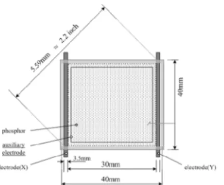
The MFFL is composed of two flat glass plates which are separated by 2 mm high barrier walls as shown schematically in Figure 1. The lamp has a pair of main electrodes parallel to each other and covered with the 60 µm thick dielectrics. The main electrodes are separated by 30 mm, and the phosphor is printed on the inner surface of both plates. The discharge gas is Ne-Xe mixture with the Xe content of 20 – 25 %. The total pressure is fixed at 100 Torr. The rectangular-shaped auxiliary electrode is formed on the opposite plate from the one where the main electrodes are formed. Except for the areal dimming operation, the auxiliary electrode is usually in the floated state. The auxiliary electrode helps to form the fully diffused glow discharge at the low voltages in the whole discharge space. As shown in Figure 2, square voltage pulses with the heights of 1 - 3 kV and frequencies of 10 - 20 kHz were employed to make the Ne-Xe discharge. The white phosphor was made by mixing red ((Y,Gd)BO3:Eu), green (LaPO4:Ce,Tb),
and blue (BaMgAl10O17:Eu) phosphors with an
appropriate mixing ratio to obtain the desired color coordinate of (0.25, 0.23).
Ultra High Luminance and Luminous Efficacy MFFL
(Mercury-free Flat Fluorescent Lamp) for Scanning
Backlights of LCD TVs
In Woo Seo, Jae-Chul Jung, Byung Joo Oh, and Ki-Woong Whang Plasma Laboratory, Display Technology Research Center, Dept. of Electrical Engineering
and Computer Science, Seoul National University, Seoul, 151-744, Korea
Tel.:82-2-880-9554, E-mail: [email protected]
18-3 / I. W. Seo
• IMID 2009 DIGEST
Fig. 1. Structure of the Mercury-free Flat Fluorescent Lamp (MFFL) with a 2.2 inch diagonal size.
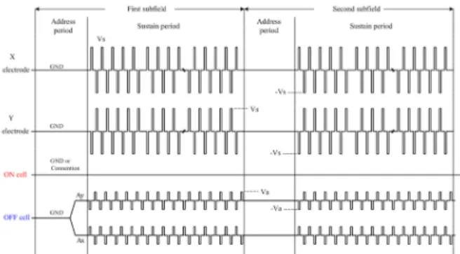
Fig. 2. Basic drive voltage waveform
2.2. Optimization of the phosphor profile and Xe content
We optimized the rear phosphor profile to enlarge the surface area of phosphor, to improve the luminance and luminous efficacy of the lamp. The schematic diagram of the optimized profile of rear phosphor is shown in Figure 3, and the real images are in Figure 4. When the width of prominence and depression (X) is 1 mm and the height of prominence (Y) is 250 µm, the surface area of phosphor is increased by 25 % and when the width is 0.5 mm, the area is increased by 50 %. Figure 5 show the dependence of luminance and luminous efficacy on the rear phosphor profile. The lamps contain Ne-Xe (20 %) at a pressure of 100 Torr with dotted front phosphor. The frequency of driving voltage is 12 kHz. As shown in Figure 5, the luminance and luminous efficacy increase with the increase of the surface area of phosphor. It is known that MFFLs with higher Xe content generally show higher luminous efficacy [5]. Figure 6 show the dependence of luminance and luminous efficacy on the Xe content with the optimized rear phosphor profile (X = 0.5 mm). The lamps contain Ne-Xe (20 % and 25 %) at a pressure of 100 Torr with 5 µm-thick flat front phosphor. As shown in Figure 6, the higher Xe content shows the higher luminance and luminous efficacy. The MFFL with optimized phosphor profile and high Xe content shows the luminance ranging from 2,600 to 17,000 nit.
When the maximum luminance of 17,000 nit was obtained, the luminous efficacy 32.5 lm/W. When the luminance was 2,600 nit, the maximum luminous efficacy of 66 lm/W was achieved as shown in Figure 6. These results were obtained with the color coordinate to be (0.25, 0.23) at 7,000 nit.
Fig. 3. Schematic diagram of the optimized profile of rear phosphor
(a) X = 1 mm (b) X = 0.5 mm
Fig. 4. Real images of the optimized application of rear phosphor
Fig. 5. Luminance and luminous efficacy of tested MFFLs
Fig. 6(b). Luminance and luminous efficacy of tested MFFLs with voltage
18-3 / I. W. Seo
IMID 2009 DIGEST • 2.3. Discharge selectivity
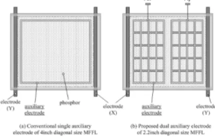
In order to control the state of the induced voltage on the auxiliary electrode, the dual auxiliary electrode of MFFLs was devised as shown in Figure 7. Figure 8 shows the distribution of the induced voltage on the auxiliary electrode. As shown in Figure 8(a), with the dual auxiliary electrodes disconnected, the induced voltage on the auxiliary electrode in floated state varies from position 0 cm (electrode X) to 3 cm (electrode Y) when the voltage of 1kV is applied to electrode X and that of -1kV applied to electrode Y. The voltage difference between the main and auxiliary electrodes become smaller than the ignition voltage, thus, the cell remains in the OFF state. Meanwhile, when the dual auxiliary electrodes are connected, the induced voltage on the auxiliary electrode has the middle electric potential of the applied voltage symmetrically across the main electrodes, as shown in Figure 8(b). The induced voltage on the auxiliary electrode is maintained at around 0 V and the voltage distribution causes a greater voltage difference between the main and auxiliary electrodes than the ignition voltage, so that local discharge occurs and moves to the fully diffuse glow discharge state. This characteristic can be used to decide the areal selective ON/OFF state of the chosen cell in the large sized multi-cell MFFL.
Fig. 7. Conventional and proposed dual auxiliary electrode
(a) Induced voltage distribution when the dual auxiliary electrode is disconnected with the bipolar pulse driving scheme
(b) Induced voltage distribution when the dual auxiliary electrode is disconnected with the bipolar pulse driving scheme
Fig. 8. Induced voltage distribution on the state of the auxiliary electrode connection
2.4. Scanning drive technique
Scanning drive technique is considered as one of the solutions to make LCDs impulsive-type displays. Blurring edges can be reduced by scanning of backlight synchronized with image data of LCD. However, in order to use the scanning scheme with the meaning results, the LCD illumination must have a small emission duty cycle, and then the backlight should be able to provide high luminance. Also the backlight should be turned on and off in a very short time. In MFFLs, the maximum luminance of 17,000 nit at the luminance efficacy of 32.5 lm/W and the maximum luminous efficacy of 66 lm/W at the luminance of 2,600 nit were obtained with the optimization of the phosphor profile and employment of the high Xe partial pressure.
Figure 9 shows the basic concept of the scanning drive and the drive scheme for scanning of multi-structured MFFL with 5 line block. In general, at a certain N block, new image data will be written to the panel from the first to the last line, and then each pixels start to change their transmittance and maintain its phase to the end of the frame as shown in Figure 10(a). In our experiment, we divided one TV frame into 5 subfields with the same weighting and controlled turning off operation sequentially from the first line to the fifth line as shown in Figure 10(b). As mentioned above, illumination period can be controlled by the connection state of dual auxiliary electrodes and the voltage condition on the auxiliary electrodes during the address period. Figure 11 shows the IR light emission under the scanning operation in one inverter system. Illumination time can be changed from a fifth to the whole period of a TV field.
18-3 / I. W. Seo
• IMID 2009 DIGEST
Fig. 9. Drive voltage waveform for areal selective 2bit dimming control
(a) Basic conceptual diagram of scanning drive
(b) Drive scheme for scanning of multi-structured MFFL
Fig. 10. Basic scanning diagram and drive scheme for scanning of MFFL
Fig. 11. Basic light emission under scanning operation
3. Conclusions
We achieved high luminance and luminous efficacy in MFFLs with the optimized phosphor profile and high Xe content gas which can be used for LCD backlights. A stable and uniform discharge could be obtained when an auxiliary electrode was deployed. The MFFL with optimized phosphor profile and Xe content showed the luminance raging from 2,600 to 17,000 nit and the luminous efficacy of 66 lm/w at 2,600 nit.
A new driving method is proposed for the areal selective light emission of a multi-structured MFFL with the bipolar pulse drive scheme and the dual auxiliary electrodes. LCDs with the backlights using this lamp can significantly improve its shortcomings such as the motion blur by adopting the scanning operation of multi-structured MFFL with a very short illumination time duty cycle utilizing its ultra high luminance level.
Acknowledgement
This work was supported by Samsung Electronics Co., LTD. LCD Division.
5. References
1. J. K. Lee, T. J. Kim, H. Y. Jung, and K.-W. Whang, SID Technical Digest, pp.1422-1424(2005). 2. J.-C. Jung, J. K. Lee, I. W. Seo, B. J. Oh, J. K. Kim,
and K.-W. Whang, IMID Technical Digest, pp. 1729-1732(2006).
3. L. S. Vagner, and Yu. B. Golubovskii,
“Measurement of Plasma Parameters in a Contracted Discharge”, J. Appl. Spectro. Vol.25, No.3, pp.1103-1108, Springer(1976).
4. Yuri P. Raizer, “Gas discharge Physics”, Springer-Verlag, pp.214-244(1991).
5. B. J. Oh, J. C. Jung, I. W. Seo, H. Kim, and K.-W. Whang, IMID Technical Digest, pp. 809-812(2008)