A Study on Visual Feedback Control of a Dual Arm Robot with Eight Joints
Woo Song Lee*, Hong Rae Kim*, Young Tae Kim**, Dong Yean Jung+, and Sung Hyun Han++* Dept. of Mechanical Design, Graduate School, Kyungnam University, Masan, Gyeongnam, 631-701, Korea ** BorgWarner TTS Korea Co., Ltd., Eumseong, Chungbuk, Korea
+ DAEHO Technology Korea Co., Ltd., 61-1, Palyong-dong, Changwon, Gyeongnam, 641-465, Korea ++ Division of Mechanical and Automation Eng., Kyungnam University, Masan, Gyeongnam, 631-701, Korea
(Tel : +82-55-249-2624; E-mail: [email protected])
Abstract:Visual servoing is the fusion of results from many elemental areas including high-speed image processing, kinematics, dynamics, control theory, and real-time computing. It has much in common with research into active vision and structure from motion, but is quite different from the often described use of vision in hierarchical task-level robot control systems. We present a new approach to visual feedback control using image-based visual servoing with the stereo vision in this paper. In order to control the position and orientation of a robot with respect to an object, a new technique is proposed using a binocular stereo vision. The stereo vision enables us to calculate an exact image Jacobian not only at around a desired location but also at the other locations. The suggested technique can guide a robot manipulator to the desired location without giving such priori knowledge as the relative distance to the desired location or the model of an object even if the initial positioning error is large. This paper describes a model of stereo vision and how to generate feedback commands. The performance of the proposed visual servoing system is illustrated by the simulation and experimental results and compared with the case of conventional method for dual-arm robot made in Samsung Electronics Co., Ltd.
Abstract: Visual Feedback, Dual Arm Robot, Eight Joints, Visual servoing, Image Jacobian
1. INTRODUCTION
Recently, robots can perform assembly and material handling jobs with speed and precision yet, compared to human workers robots, are hampered by their lack of sensory perception. To address this deficiency considerable research into force, tactile and visual perception has been conducted over the past two decades.
Visual servoing is the fusion of result from many elemental areas including high-speed image processing, kinematics, dynamics, control theory, and real-time computing. It has much in common with research into active vision and structure from motion, but is quite different from the often described use of vision in hierarchical task-level robot control systems. Many of the control and vision problems are similar to those encountered by active vision researchers who are building robotic heads. However the task in visual servoing is to control a robot to cope with its environment using vision as opposed to just observing the environment.
Most visual servoing problems can be considered as nonlinear control problems with the gray level of each two dimensional pixel array being an observation. The difficulty of the problem is the size and the nonlinearity. The size of the observation is larger than ten thousand and they have nonlinear interaction with each other. A few researches based on the stochastic models of the two-dimension observation are found, but most visual servoing schemes uses the features of the image as the observation. To manipulate objects with complex shapes, it is important to deal with complex features such as spheres and cylinders. However, the time extracting complex features will become too long based on limited hardware. Accordingly, visual servoing scheme which utilizes many features effectively is required. Furthermore exploiting the information carefully from the features will give robust and accurate control performance [4-6].
Sanderson et al. proposed a feature-based approach and defined the Jacobian of ideal inverse interpretation which was considered as the infinitesimal change of the relative position and orientation between the camera and the object in the environment.
Newman et al. proposed an adaptive control law based on a single input single output model and a feature selection criterion were proposed [10-12]. The criterion addressed the choice of which feature should be used to control each actuator, where the number of selected features is equal to the number of the actuator. Feddema et al. [3-5, 6] also studied the selection method of the features to make the Jacobian good condition. Real time experiment of gasket tracking showed that the proper selection of features is necessary to minimize the effect of image noise.
Papanikolopoulos et al. [5-7] experimentally examined many control algorithms including Proportional-Plus- Integral, pole assignment and linear quadratic gaussian. Some adaptive control schemes were also examined in [8]. These approaches do not consider to use the redundant features which are defined as the features whose number is more than the degrees of freedom of the robot manipulator.
Chaumette el al. [8] and Espiau el al. [9] derived the interaction matrix, and introduced the concept of task function. Chaumette [2] extended the task function approach to the complex features. Jang and Bien [10] mathematically defined the “feature”, and derived the feature Jacobian matrix. The authors [12] derived the image Jacobian, and used its generalized inverse and PD control to generate the hand trajectory. These schemes are based on the generalized inverse of the Jacobian. Redundant features can be used. However, the parameters to improve the control performance are very limited and the controllability of the redundant features are not discussed.
The authors proposed a linearized dynamic model of the visual servo system and linear quadratic control scheme for redundant features [11,13].
The controllability problem was discussed but the performance improvement by utilizing the redundant features was not presented.
This paper presents how the control performance of the feature-based visual servoing system is improved by utilizing redundant features. Effectiveness of the redundant features is evaluated by the smallest singular value of the image Jacobian which is closely related to the accuracy in the world coordinate
system. Usefulness of the redundant features is verified by the real time control experiments. To illustrate the accuracy of the redundant visual servo system, real time experiments on the Dual-Arm robot with eight joints are carried out. Translation and rotation step response with three, four and five features are examined in this experiment.
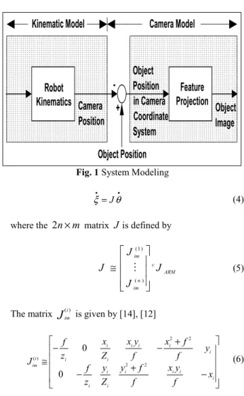
2. SYSTEM MODELINGAND FORMULLATION The object image moves with the joint angle to the object image, which is composed of the kinematic model and the camera model as shown in Fig.1. Suppose that a camera is mounted on the robot hand and the object does not move. The kinematic model is a map from the joint angle to a position of the camera. Since the camera is on the robot hand, the camera position is uniquely defined by the joint angle
θ
based on the kinematic structure of the robot. The camera model is a map from the position of the camera to the camera to the image of the object.The object image is generated by the perspective of the relative position between the camera and the object. The perspective projection is a map between two different representations of the position of the object, i.e., the representations in the camera coordinate system
[
XYZ]
Tand in the image plane[ ]
xy
T.The perspective projection with f being the focal length of the lens is given by
[ ] [
x
y
TX
Y
]
T(
f
/
z
)
=
(1) Suppose that there are n feature points, namely[
]
T i i i i XYZp
=
(i=1,....,n) , on an object and the corresponding positions in the image plane are[ ]
T i i i=
xyξ
(i=1,....,n). Assume that the shape and the size of the object are known and constant (i.e., the object is a rigid body). Thenξ
i for i=1,....,n become functions of the joint angleθ
. Let us define a 2n dimensional feature vector by[
T]
Tn T
ξ
ξ
ξ
≅ 1L
. Then the system model for n feature points is defined by the mapψ
:Rm→R2n from the joint angleθ
to the feature vectorξ
as follows:( )
θ
ξ
ψ
≅ (2)where m is the number of the joints of the robot.
Since the task must be carried out in the nonsingular region of the robot, the nonsingular region is called the operation region
m R ⊂
Μθ . We restrict the robot motion in the operation region. Thus the robot Jacobian J robot is invertible in the working area. It is useful to introduce the feature manifold
Μ
, which is defined by } ), ( : { 2 θθ
θ
ψ
ξ
ξ
∈
=
∈
Μ
=
Μ
R n (3) The features on the feature manifold is called the admissible features. If the features are admissible, then the robot Jacobian is invertible by definition. In equation (3),θ
represents joint angle.Differentiation of the system model yields
Robot
Kinematics
Feature
Projection
Camera
Position
Object
Image
Object
Position
in Camera
Coordinate
System
Object Position
+
-Camera Model
Kinematic Model
Fig. 1 System Modeling
• •
= θ
ξ J (4)
where the 2
n
×
m
matrixJ
is defined byARM c n im im J J J J ≅ ) ( ) 1 ( M (5) The matrix
J
i im ) ( is given by [14], [12] − + − + − − ≅ i i i i i i i i i i i i i i i im x f y x f f y Z y z f y f f x f y x Z x z f J 2 2 2 2 ) ( 0 0 (6)and called the image Jacobian [12]. cJARM is the robot Jacobian expressed in the camera coordinate system. Since the vector
θ
&∈R
6ARM
cJ is the linear and angular velocities of the camera expressed in the camera coordinate system,
J
iim ) (
becomes the infinitesimal change of the position of the camera.
Moreover, ARM c i im J J i
J()≅ () becomes the infinitesimal change of the features according to the infinitesimal change of the joint angles.
The degenerated features are the features for which the extended image Jacobian is not full rank. The degenerate features should be avoided because the inverse map (the map from
ξ
toθ
) becomes singular. Thus, when the number of joints is m,m J
rank (
θ
)= ∀θ
∈Μθ (7) is required for all admissible features. To satisfy this condition2 /
m
n≥ is an obvious necessary condition, but it is not sufficient for some cases.
For example, consider a general six degree of freedom )
6
(m= . In this case, n≥3 is necessary. If n=3 , 6
〈
J
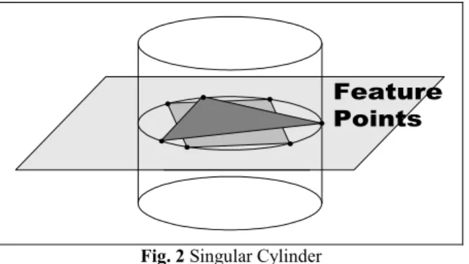
rank the camera lies on the cylinder(Fig. 2) which includes the three points and the axis of which is perpendicular to the plane containing these points. For any attitude of the camera, Jis singular. Thus n=3 is not sufficient and n≥4 is desirable. For the case of n=4, we have the following theorem.
Feature
Points
Fig. 2 Singular Cylinder
Theorem 1: Suppose that there are four points on a plane and the corresponding feature vector is admissible. Then the extended image Jacobian is full rank if any three feature points out of them are not collinear in the image plane.
Proof : Let the plane on which the four points exist be
r
qY
pX
Z
=
+
+
. Then Zi satisfies Zi = pXi+qYi+r for i=1 L, ,4. Substituting (1) into this yieldsr qy px f Z f i i i − − = (8)
And substituting this into (6) yields
N M J i i im = ) ( (9) where Mi and N are defined by
= f y f y x y x f f y x f x y x f M i i i i i i i i i i i / / 0 0 0 / / 0 0 0 2 2 , − − − − − − − = 0 0 0 0 0 0 0 0 0 0 0 1 0 0 0 0 0 0 0 0 0 0 0 0 1 0 0 0 0 1 0 0 0 0 0 1 1 r q r p q r p r q p r r r N (10)
Then we obtain ARM
cJ MN J= , where
M
=[
M
TM
TM
TM
T]
T 4 3 21 . It is straightforward to see that
2 2 1 1 4 4 1 1 4 4 3 3 4 4 3 3 2 2 3 3 2 2 1 1 1 1 1 1 1 1 1 1 1 1 1 1 det y x y x y x y x y x y x y x y x y x y x y x y x M= • • • (11)
Thus
M
is invertible because any three feature points are not collinear. On the other hand, ifp
2+q
2≠0, the first six rows ofN
is linearly independent. If p= q=0, the first four and the last two rows are linearly independent. Thus rank6 =
N
. finally, since all features are admissible, ARM cJ
is invertible. Therefore, the extended image Jacobian
J
is full rank.3. ANALYSIS OF VISUAL SERVOING
For evaluating the performance of the feature-based visual servo system, it is useful to discuss the ratio of the joint angle error to the feature vector. The following theorem shows that increasing the number of the feature point is an effective way to improve the performance.Let the joint error be ∆θ=θ−θd and the feature error be d
ξ
ξ
ξ
= −∆ . Define the worst joint/feature error ratio
ER
, called sensitivity, as follows:) ( 1 sup min 0 ||
J
ER
β
ξ
θ
ξ ∆ = ∆ = ≠ ∆ (12)where
β
min(J
) is the minimum singular value ofJ
. Then the sensitivityER
decreases strictly by increasing the number of non-degenerated features on the object.Let
J
n be the image Jacobian for n feature points andJ
n+1 be the image Jacobian obtained by adding an extra feature point to the already existing feature points.Then we have = + +1 (n1) n n J J J (13) where J(n+1) is the 2×
m
image Jacobian corresponding to the newly added feature point. It is straightforward to see that) ( ) ( min 1 min
J
n ≤β
J
n+β
(14) The equal sign holds only if each row of J(n+1) is linearly dependent toJ
n, i.e., only ifJ
n+1 is not full rank. Since we assumed that the features are not degenerated, the equal sing should be dropped. Thus adding extra feature points strictly increases the minimum singular value.This theorem says that we can reduce the joint angle error by increasing the number of feature points.
Linearizing the model (2) with the feature vector being the state vector yields an uncontrollable model because
ξ
can not move arbitrarily in 2n.
R
[13]. A simple way to avoid this problem is to mapξ
∈Μ onto the tangent space of Μby using the following transformation.) ( d T d
J
z
=ξ
−ξ
(15) whereJ
d =J
(θ
d) is the image Jacobian at the desired point[16]. Note thatz
andθ
are one-to-one in the neighborhood ofθ
d. The dynamics of the feature error on the tangent space of the manifold Μ is given byθ
θ
& &J
J
( )z
T d = (16) Thus, for a simple continuous time control lawθ
&=−Kz
with a positive definite constant matrixK
yields an asymptotic stability ifJ
dTJ
(θ
) is positive definite. It is shown that this condition is satisfied fairly large region aboutθ
d [13].4. EXPERMENTS AND DISCUSSION
As shown in Fig.3, the objects are white boards with three, four and five black marks. Three points are arranged to make a regular triangle with edge length 120mm. Four points are on corners of a square with edge length 120mm. All marks are on a plane except the one of five points at the center of the square, which has height 60mm. Dual-Arm robot holds the objects and a camera(Fig.4). The world coordinate system
ω
X−ω
Y−ω
Z is at the base of the Dual-Arm robot. A nominal camera position is almost in front of the plane on which the marks exist. To avoid the singular cylinder(Fig.2) the optical axis and the normal axis of the object plane are not aligned. The distance is about 1000mm. The features are thex
andy
coordinates of the center of the image of each mark. Computing their minimum singular values at the reference position gives35 . 0 ) ( 3 min = J = β , βmin = J( 4)=0.65, (17) 60 . 3 ) ( 5 min = J = β Thus accuracy of the position control of the camera in the 3D work space will be improved by using 5 features. We carried out many step tests to this observation.
The first experiment is a step motion in vertical axis. The object is moved upward for 120mm (i.e., in
ω
Z direction). The camera is controlled to keep the features at the initial positions. Thus the initial values and the reference values are the same. The object motion is considered as a disturbance for the plots of the features in the image plane. On the other hand, the object motion becomes the step change of the reference position for the plots of the camera motion in the world coordinate system. Since Dual-Arm robot has only 6 degrees of freedom, the orientation of the object changed slightly. Thus, the reference orientation is [2.8, 0, -1.8] degrees expressed in the Euler angles, say p,η
,φ
.120mm 120mm 120mm
8 mm 8 mm
60 mm height :40 mm
Fig. 3 Configuration of Feature Points
Fig. 4 Experimental Setup
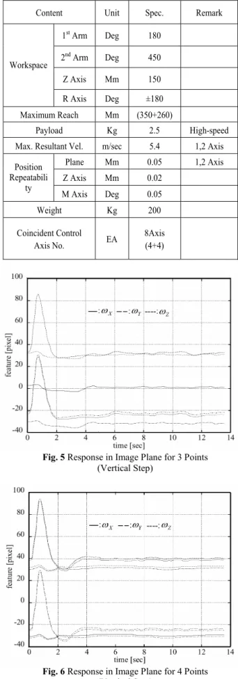
Table 1. Specification of Dual Arm Robot
Content Unit Spec. Remark
1st Arm Deg 180 2nd Arm Deg 450 Z Axis Mm 150 Workspace R Axis Deg ±180 Maximum Reach Mm (350+260) Payload Kg 2.5 High-speed
Max. Resultant Vel. m/sec 5.4 1,2 Axis
Plane Mm 0.05 1,2 Axis Z Axis Mm 0.02 Position Repeatabili ty M Axis Deg 0.05 Weight Kg 200 Coincident Control Axis No. EA 8Axis (4+4)
Fig. 5 Response in Image Plane for 3 Points (Vertical Step)
Fig. 6 Response in Image Plane for 4 Points (Vertical Step)
Fig. 7 Response in Image Plane for 5 Points (Vertical Step)
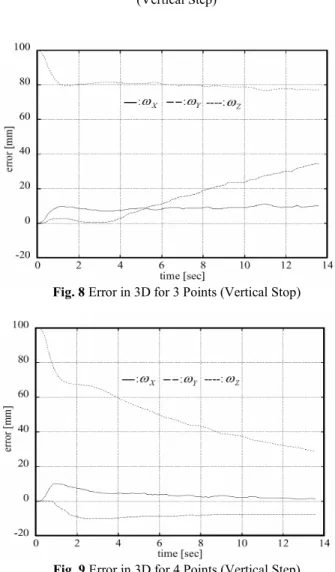
Fig. 8 Error in 3D for 3 Points (Vertical Stop)
Fig. 9 Error in 3D for 4 Points (Vertical Step) Fig. 5 has six curves which show the
x
andy
coordinates of the three feature points in the image plane. The horizontal axis is the time. The curves disturbed largely are they
coordinates and the others are thex
coordinates. They are almost stabilized in two seconds. Fig.7 depicts the image coordinates of five points. All responses in the image plane are similar to each other.The plots in Fig.8 depicts the position errors of the camera for three feature points (measured in the world coordinate system). The error in
ω
Y direction is diverging. However, asFig. 10 Error in 3D for 5 Points (Vertical Stop) shown in Fig. 9., the response of the camera position with four feature points is stabilized. It is sluggish, and it takes more than 20 seconds to stabilize the disturbance. Fig. 10. is the response with five feature points. It is improved very much for both speed and accuracy. The steady state errors are smaller than 5mm for all directions
5. CONCLUSION
In this paper, it has been presented how the control performance of the feature-based visual servo system is improved by utilizing redundant features. Effectiveness of the redundant features is evaluated by the smallest singular value of the image Jacobian which is closely related to the accuracy in the world coordinate system. It shows that the accuracy of the camera position control in the world coordinate system was increased by utilizing redundant features. Real time experiments on dual-arm-robot were carried out to evaluate the improvement of the accuracy and speed by utilizing the redundant features. The results verifies that the minimum singular value of the extended image Jacobian plays an important role for performance improvement of the feature-based visual servoing.
ACKNOWLEDGEMENTS
This research was supported by the New University for Regional
Innovation program of the Ministry of Education & Human Resources Development (NURI MECHANO 21).
REFERENCES
[1] K. Hashimoto et al.,1991, “Image-based dynamic visual servo for a hand-eye manipulator,”in MTNS-91, Kobe, Japan, pp. 609~614.
[2] Sung Hyun Han, Man Hyung Lee, Hideki Hashimoto, 2000, “Image-Based Servoing Control of a SCARA Robot” KSME International Journal, Vol. 14, No. 7, pp. 782~788.
[3] P. K. Allen, A. Timccnko, B. Yoshimi, and P. Michelman, 1993, "Automated tracking and grasping of a moving object with a robotic hand-eye system," IEEE Trans. Robotics and Automation, vol. 9, no. 2, pp. 152~165.
[4] K. Hashimoto, T. Ebine, and K. Kimura, 1996,“Visual servoing with hand-eye manipulator―optimal control
approach,”IEEE Trans. on Robotics and Automation, vol. 12, no. 5, pp. 766~774.
[5] K. Hashimoto. T. Ebine, K. Sakamoto, and H. Kimura, 1993, “Full 3D visual tracking with nonlinear model-based control,”in American Control Conference, San Francisco, Calif., pp. 3180~3184.
[6] L. E. Weiss, A. C. Sanderson, and C. P. Newman, 1987, "Dynamic sensor-based control of robots with visual feedback," IEEE J. Robotics and Automation, vol. RA-3, no. 5, pp. 404~417.
[7] J. T. Feddema and O. R. Michell, 1989, "Vision guided servoing with feature-based trajectory generation," IEEE Trans. Robotics and Automation, vol. 5, no.5, pp. 691~ 700.
[8] K. Hashimoto et al., 1991,“Manipulator control and with image-based visual servo,”in IEEE Int. Conf. Robotics and Automation, Sacramento, Calif., pp. 2267~ 2272. [9] W. Jand and Z. Bien, 1991,“Feature-based visual
servoing of an eye-in-hand robot with improved tracking performance,”in IEEE Int. Conf. Robotics and Automation, Sacramento, Calif., pp. 2254~2260.
[10] B. Espiau, F. Chaumette, and P. Rives, 1992,“A new approach to visual servoing in robotics,”IEEE Trans. Robotics and Automation, vol. 8, no. 3, pp. 313~ 326. [11] F. Chaumette, 1994, "Visual servoing using image
features defined upon geometrical primitives," in Proc. 33rd Conf. Decision and Control, Lake Buena Vista, Florida, pp. 3782~3787.
[12] J. T. Feddema, C. S. G. Lee, and O. R. Michell, 1987, "Automatic selection of image features for visual servoing of a robot manipulator," in IEEE Int. Conf. Robotics and Automation, Scottsdale, Ariz, pp. 832~837. [13] N. Papanikolopoulos and P. K. Khosla, 1993, “Adaptive
robotic visual tracking: theory and experiments,” IEEE Trans. Automatic Control, vol. 38, no. 3, pp. 429~445. [14] N. Papaniklolpoulos, P. K. Khosla, and T. Kanade, 1991,
“Vision and control techniques for robotic visual tracking,”in IEEE Int. Conf. Robotics and Automation, Sacramento, Calif., pp. 857~864.
[15] F. Chaumette, P. Rives, and B. Espiau, 1991, “Positioning of a robot with respect to an object, tracking it and estimating its velocity by visual servoing,”in IEEE Int. Conf. Robotics and Automation, Sacramento, Calif., pp. 2248~2253.
[16] H. Longuet-Higgins and K. Prazdny, 1984, “The interpretation of a moving retinal image,”Proc. Royal Soc. London Ser. B, vol. 208, pp. 385~397.