A Study on Phase Bearing Error using Phase Delay of Relative Phase Difference
Kwan Hyeong Lee
Professor, Division of IT Convergence, Daejin University, Korea
[email protected]
Abstract
This study proposes a method to reduce the phase error of the received signal to detect the object bearing. The phase shift of the received signal occurs due to the multipath of the signal by natural structure or artificial structures. When detecting the direction of the object using radio waves, the phase of the received signal cannot be accurately detected because of the phase bearing error in the object detection direction. The object detection direction estimation depends on the phase difference, antenna installation distance, signal source wavelength, frequency band and bearing angle. This study reduces the error of the phase bearing by using the phase delay of the relative phase difference for the signals incident on the two antennas. Through simulation, we analyzed the object direction detection performance of the proposed method and the existing method. Three targets are detected from the [−15°, 0°, 15°] direction. The existing method detects the target at
[−13°, 3°, 17°], and the proposed method detects the at [−15°, 0°, 15°]. As a result of the simulation, the target detection direction of the proposed method is improved by 2 degrees compared to the existing method.
Keywords: Phase delay, Target estimation, Phase difference, Array antenna, Target signal processing
1. Introduction
Radar transmits radio waves to obtain information using the signals reflected from the targets. The radar antenna receives a mixed multiples signal, which is a transmission signal, an interference signal, a noise signal and a clutter signal. The transmitted signal is converted into a multipath signal by the artificial structure and the natural environment [1]. The radar receiver obtains an information signal by removing the interference, the noise and the clutter signals through digital signal processing to extract to the information signal. Extracting the information signal from the received signal requires a number of technical processing methods for the signal processing algorithm to remove the noise, the interference, and the clutter signals. The target estimation enhancement detection methods include adaptive array antenna, antenna aperture size, adaptive array algorithm, beamforming method, angle of arrival estimation, digital multiple receiving beam technology, and position error reduction technology [2-3]. The target detection signal improves the direction detection accuracy by removing the interference, the noise, and the clutter signals by applying signal processing technology. The target signal processing technologies include rotation detection method, amplitude comparison detection method, and phase delay processing detection method [4]. The rotation detection method acquires information
IJIBC 21-2-11
Manuscript Received: February. 18, 2021 / Revised: February. 22, 2021 / Accepted: February. 24, 2021 Corresponding Author: [email protected]
Tel: +82-31-539-1925, Fax: +82-31-539-1890
from the received signals by mechanically rotating the small beam width antenna to radiate radio waves in spatial. The amplitude comparison detection method estimates an information signal by comparing the amplitudes of received signals incident on the array antenna. In the phase comparison method, the information signal is estimated by using a phase difference of the array antenna received signal. This method has higher target detection accuracy than other methods. In the phase comparison detection method, the performance of the detection system is determined by the array antenna spacing, the frequency band, the signal wavelength, and relative signal phase difference [5-6]. In particular, the relative signal phase difference of the receive signal is a very important variable and causes the important error in the target direction detection. Therefore, if the error occurs in the relative signal phase difference of the received signal, the target direction detection cannot be accurately estimated. K. Chang [7] developed a computer program using a statistical model of error information to reduce bearing angle errors in a phased array antenna system. This method uses fractal theory to obtain the dynamic system azimuth error of the phase array by turret and electromechanical scan of the array. Lv.Yakun [8] studied a phase compensation algorithm based on CS-FMEA (Circular Shifting Fast Minimum Entropy Algorithm). This method reduces the phase error compensation performance by using the index for image entropy and operation efficiency by analyzing the phase error effect on the signal and the phase compensation effect of the minimum entropy algorithm based on the image geometry model of the synthetic aperture LiDAR. Tingzhu.Fang [9] studied a deramping-based method that extends the basic method to complement the existing channel phase error estimation algorithm in azimuth multi-channel composite aperture radar system. This method reduces the existing channel phase error by multiplying each channel signal with the corresponding deramp phase to change the Doppler center. This paper studies a method to reduce the phase error for detecting the object direction by using the phase difference of the incident signal of the array antenna. The composition of this paper describes phase difference signal analysis in chapter2 and the phase bearing error signal enhancement method in Section 3. Section 4 compares and analyzes the performance of the proposed method and the existing method, and finally, Section 5 concludes.
2. Phase difference signal analysis
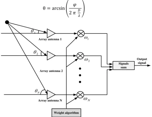
The method for phase delay is a method of detecting the direction of an object by measuring the difference in propagation delay time in space with the electrical phase component of the signal in an environment where the distance between the antenna installations cannot be distanced. The antenna receives a signal in space and converts it into an electrical high-frequency signal, and the high-frequency signal is input to the RF of a mixer. A local oscillator (LO) inputs the tuned LO signal to the mixer's LO terminal using frequency information. The mixer generates an intermediate frequency (IF) signal corresponding to the frequency difference between the received signal and the tuned signal, which is input to a phase discriminator through a limiting amplifier. Figure 1 shows a receiving system for detecting the object. The signal received from the antenna is processed using a weight algorithm. The signal received by each antenna has the phase difference in the received signal according to the position of the array antenna. When the first array antenna is referenced, the signal incident on the second array antenna has the phase difference from the first antenna. The phase discriminator outputs two signals having a sine component and a cosine component according to the relative phase difference of the input time signal. Both the signals always have a signal strength corresponding to this phase difference by 90 degrees. The phase difference is calculated by calculating the magnitude and ratio of the two measured signals. This phase difference is transmitted to the direction finder and processed with frequency information to indicate object orientation detection. When the distance between the signal source and the measuring antenna satisfies the far-field condition, the signal received from the signal source forms a plane wave. The phase discriminator outputs two signals having a sine component and a cosine component according to the relative
phase difference of the input time signal. Both the signals always have a signal strength corresponding to this phase difference by 90 degrees. The phase difference is calculated by calculating the magnitude and ratio of the two measured signals. This phase difference is transmitted to the direction finder and processed with frequency information to indicate object orientation detection. When the distance between the signal source and the measuring antenna satisfies the far-field condition, the signal received from the signal source forms a plane wave. The received signal of the first array antenna is represented as follows [10].
V1 = A exp (𝑗𝜔𝑡 − 2 𝜋 𝑑
𝜆 ) (1) A is the signal amplitude, 𝑑 is the propagation distance, and 𝜆 is the signal wavelength. The received signal of the second array antenna is a signal as long as Dsinθ based on the first array antenna, and the received signal can be expressed as follows
V2 = A exp (𝑗𝜔𝑡 − 2 𝜋 (𝑑+𝐷𝑠𝑖𝑛𝜃)
𝜆 ) (2) Here, D is the distance between the array antennas, and θ is the object direction measured with respect to the array antenna. The received voltage of the two antennas is composed of the voltage strength and phase component determined by the strength of the signal source and the antenna gain. In the phase discriminator, he relative phase difference between the two signals is expressed as follows.
ϕ =2 𝜋
𝜆 𝐷 𝑠𝑖𝑛𝜃 (3) The phase discriminator outputs the relative phase difference as sin and co-sin components, so the measured phase difference is calculated as the ratio of the two components as follows:
φ = arctan (𝑠𝑖𝑛𝜃
𝑐𝑜𝑠𝜃 ) (4) The direction detection processor uses the measured phase difference and the frequency information to display the bearing angle as follows.
θ = arcsin ( 𝜑 2 𝜋 𝐷 𝜆 ) (5) Signals sum Array antenna 1 Weight algorithm Output signal Array antenna 2 Array antenna N 1 2 N
1 2 N 3. Phase bearing error signal enhancement method
The phase difference measured by the phase difference is within 360 degrees, so if the signal source frequency is greater than the array antenna installation distance and the array antenna installation distance is longer than the operating frequency band, the signal source changes and the phase difference repeats 360 degrees. The ambiguity of the phase difference in the azimuth measurement range is determined by the ratio of the distance between the array antennas and the wavelength of the signal source. The variable that affects the phase center is the frequency of the signal source, and because the phase center of the array antenna changes with frequency, the physical antenna center is fixed during installation, so the phase difference measurement according to frequency is different from each other. In order to reduce the error due to the phase center change according to the frequency, it is necessary to correct the phase center for each frequency or to make the phase center constant within the frequency band used when manufacturing the antenna. The phase discriminator, which measures the phase difference of the received signal between two antennas, plays an important role in the performance of the phase comparison direction finder. The phase discriminator consists of a phase changer and a signal detector. Since the characteristics change according to the frequency, input signal strength, and phase difference, the measured amount of these variables must be corrected when measuring the phase. The factor used for the receiving channel between the antenna and the phase discriminator must not affect the phase, especially the phase transfer characteristics between the two receiving channels must be the same. The phase difference received signal of the second antenna and the first antenna is expressed as follows.
R1(𝑡) = 𝐴1 𝑐𝑜𝑠(𝜔1𝑡) (6) R2(𝑡) = 𝐴2 𝑐𝑜𝑠(𝜔2𝑡 + 𝜙) (7) Here,𝜔 represents each frequency, and 𝜙 represents the phase difference. The local oscillator signal having an initial phase value is represented as follow.
𝐿𝑜(𝑡) = A𝐿 𝑐𝑜𝑠(𝜔𝐿𝑡 + 𝜙𝐿) (8) The two output signals of the mixer are show as follows.
M1= 𝑅1(𝑡) ∙ 𝐿𝑜(𝑡) (9) M2= 𝑅2(𝑡) ∙ 𝐿𝑜(𝑡) (10) The output of the mixer shows the phase difference between the two frequency components. Since the phase discriminator only needs the (𝜔𝑁−𝜔𝐿) frequency component to operate at a low frequency, it is possible to measure the phase difference in the desired IF signal by using a filter with a small bandwidth at this frequency. The phase difference of the received signal between the two antennas is shown in Equation (3). The rate of change of phase difference for the phase bearing change is expressed as follows by differentiating Equation (3).
dϕ 𝑑𝜃 =
2 𝜋
𝜆 𝐷 𝑐𝑜𝑠𝜃 (11) The phase bearing rate is expressed as follows by substituting the differential increase/decrease ∆ in Equation (11).
∆θ =2 𝜋 ∆ϕ 𝜆 𝐷 𝑐𝑜𝑠𝜃
(12) The variance for the phase bearing error in the target direction detection performance is expressed as follows.
σ = √ ∆ϕ 2 (2 𝜋𝜆 𝐷 𝑐𝑜𝑠𝜃)2
Here, ∆ϕ = c/f, cis the propagation constant, and f is the detection frequency. The phase bearing error is determined by the phase difference ratio, the antenna installation interval, the signal source frequency, and the incident phase bearing angle of the single source.
4. Simulation
This section simulates the proposed method and the existing method to detect the direction of three objects by equation (12). The proposed method detects an object by reducing the phase orientation error using the delay time of the relative phase difference. The existing method does not apply the delay time of the relative phase difference.
The simulation conditions are as follows.
-. 3 targets are located in the phase direction of [-15°, 0°, 15°].
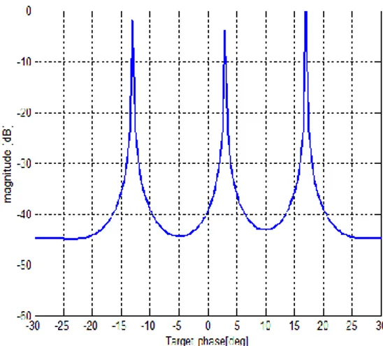
-. The interval between antennas is set to half-wavelength, and the signal-to-noise ratio is set to 20dB. Fig. 1 shows a graph that detects the directions of three objects in a method without applying the delay time of the relative phase difference. Fig. 2 detects the direction of three objects at [-13°, 3°, 17°] and an error occurs by about [2°]. Fig. 3 shows that no phase direction error occurs by detecting all three object directions at [-15°, 0°, 15°] with the method proposed in this study.
Figure 2. Target direction estimation using existing method
5. Conclusion
In this study, the method of estimating target detection was studied by reducing the error of detecting the phase bearing direction. In phase direction detection, detection errors are caused by the frequency of the signal source, the distance between the antennas, the thermal noise, the signal-to-noise ratio, and the phase imbalance of the receiving channel. Methods for reducing the phase direction detection error include extending the antenna installation interval and increasing the number of array elements, but these methods are not physically and economically effective. In addition, the method of improving the accuracy of the object direction detection must resolve signal ambiguity. In this study, the phase error was reduced by applying the delay time of the relative phase error to improve the detection accuracy of the phase direction. Through simulation, the performance of the proposed method and the existing method was analyzed. It can be seen that the error of the proposed method is reduced compared to the existing method in the target direction estimation.
References
[1] Peebles Jr., P.Z., Radar Principles, John Wiley & Sons, pp. 17-153, 1998. [2] Merrill. Skolnik, Radar Handbook, Mcgraw-Hill, pp. 10-78, 1997.
[3] Merrill. Skolnik, Introduction to Radar Systems, Mcgraw-Hill, pp. 57-98, 2000.
[4] Weizhong. Yan, “DOA Measurement of Moving Targets”, in proc. IEEE Cross Strait Radio Science & Wireless Technology conference, pp.1-3, Dec. 13, 2020. DOI: 10.1109/CSRSWTC50769.2020.9372632.
[5] Haw. Chen, and Erwin, H.W.Chan, “Photonic-Based RF Signal Phase Detector with Wide Operating Frequency Range and High Resolution”, IEEE Photonics, pp.7900709, Vol. 13, No. 2, April 2021. DOI: 10.1109/JPHOT.2021.3066992.
[6] Yuanling, Huang and Yourong, Lu, “Small Carrier Frequency Difference Detection based on the Relative Phase Entropy”, in Proc. IEEE International Symposium on Communications and Information Technologies, pp.1417-1422 , Dec. 17, 2007, DOI: 10.1109/ISCIT.2007.4391973.
[7] K.Chang, S.Johnson, R.Foltz, and R.Castner, “Angle Error Simulation for Phased Array Radar System”, IEEE Antennas and Propagation Society Symposium, in proc. pp. 1400-1403, June. 24, 1991, DOI: 10.1109/APS.1991.175111.
[8] Lv.Yakun, Wu.Yanhong, Wang.Horgyan, and Sherg.Shiqinag, “Phase Error compensation Algorithm of Inverse Synthetic Aperture LiDAR base on CS-FMEA”, IEEE International Conference on Computer and Communications, pp. 1-5, Dec. 13, 2017 . DOI: 10.1109/ICCC41418.2017.
[9] Tingzhu.Fang, Heng.Zhang, Da.Liang, Lei.Zhang, Huaitao.Fao, “A Channel Phase Error Estimation Method for Multichannel TOPS and Multichannel Sliding Spotlight SAR Imaging”, IEEE Geoscience and Remote Sensing Letters, pp. 1-5, Vol.1, 2021. [10] Xinagrui.Dai, Xiaofei. Zhang, and Yunfer.Wang, “Extend DoA-Matrix for DoA Estimation via Two Parallel Linear Arrays”, IEEE Communications Letters, pp. 1981-1984, Vol. 23, No. 11, 2019, DOI: 10.1109/LCOMM.2019.2939245.