Development of MCC Based Diagnostic Method for Motor-Operated Valves
Shin-Cheul Kang, Sung-Keun Park, Do-Hwan LeeKorea Electric Power Research Institute, 103-16 Munji-dong Yuseong-gu, Daejeon, 305-380, Korea [email protected]
Jang-Bom Chai, Chan-Woo Lim
M&D Corp., San 5 Wonchon-dong, Paldal-gu, Suwon, Kyungki-do, 442-749, Korea [email protected]
1. Introduction
Motor-operated valves (MOVs) are essential components to control the flow of various systems in nuclear power plant. Since, the operational failures of the safety-related MOVs could affect the reliability of the plant, those MOVs have been tested by attaching several sensors at the valves to verify the condition. To reduce the cost and manpower needed for diagnostic test, MCC (Motor Control Center) based diagnostic methods have been developed in US [1]. However, all those methods have low accuracy and are applicable to specific MOVs. In this paper, a newly developed method is introduced which estimates the motor torque and the stem torque or the stem thrust, which are the most important diagnostic variables, with voltages and currents acquired at MCC non-intrusively.
2. Operational Principle of an MOV
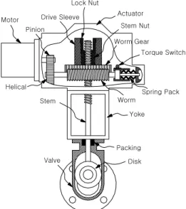
An MOV consists of a motor, an actuator, and a valve body. In this study, two MOVs with three phase induction motors are selected for experiment, and the valve type is gate and globe respectively. The manufacturers of two MOVs are different and very popular in nuclear power plant. Figure 1 shows a schematic diagram of a MOV. The actuator is driven by a motor which is bolted to the actuator gear box. The pinion gear, which is attached to the motor shaft, drives a gear train. The gear train drives a worm that is splined onto the opposite end of the worm shaft. This worm assembly is capable of moving axially as it revolves with the worm shaft. The axial movement is a means of controlling the output torque of the operator. The worm drives a lugged worm gear which rotates the drive assembly. A stem nut is spline fit into the drive sleeve and secured in place by the stem nut lock nut. As the drive sleeve rotates, the stem nut raises or lowers a valve stem. When the worm gear can no longer rotate (valve is closed, or obstructed), the worm then slides axially along its splined shaft compressing a spring pack. This axial movement operates a torque switch in the control circuit, causing the motor to be de-energized. There are normally two different switches that control the MOV: a geared limit switch and a torque switch. Usually, the torque switch is used to secure the required stem thrust when closing and a geared limit switch to stop the valve stroke at the previously determined position when opening. After the motor turns off, the motor rotates more due to the inertia of moving parts which increase the stem thrust further.
Motor Pinion Drive Sleeve Lock Nut Actuator Stem Nut Worm Gear Torque Switch Spring Pack Helical Worm Yoke Stem Packing Disk Valve
Figure 1. Schematic diagram of MOV
3. NEET Method1
NEET (Non-invasive Evaluation of Electric Torque) method calculates electric output torque of three phase induction motors. NEET method is developed on the basis of several assumptions. First, the stator windings are assumed to be sinusoidally wound so is to couple only to the fundamental-space-harmonic component of air-gap flux. Second, the self-inductances of the rotor are assumed not to vary with rotor angular position. Finally, linear magnetics are assumed.
Under these assumptions, the air-gap torque produced by a two-phase induction motor is given by
(
λsα sβ λsβ sα)
E P i i
T = − (1) where λsα and λsβ are the flux linkages of the two stator phases and isα and i are the currents of the sβ two stator phases [2,3,4]. The currents isα and i can sβ be directly measured at the stator terminals. The flux linkages can also be determined from terminal measurements. For a two-phase machine,
⎥ ⎦ ⎤ ⎢ ⎣ ⎡ + ⎥ ⎦ ⎤ ⎢ ⎣ ⎡ = ⎥ ⎦ ⎤ ⎢ ⎣ ⎡ β α β α β α λ λ s s s s s s s dt d i i R v v (2) where v and sα v are the two stator voltages and sβ R s
is the stator phase resistance. Thus, the motor torque is expressed only in terms of stator variables which can be measured remotely like in MCC.
1
Some of the contents of this paper is MIT patent, Transactions of the Korean Nuclear Society Autumn Meeting
The experimental verification of the torque estimator was done using a dynamometer setup which consisted of a motor, a torque cell and a load simulator. The torque cell was placed between the motor and the load simulator to measure the torque transferred from the motor to the simulator. Motor torque was estimated by MOVIDS 2 (Motor Operated Valve Intelligent Diagnostic System) which measured 3 phase input voltages and currents and had NEET algorithm inside. The load to the motor was controlled with the load simulator. Experiments were carried out under 4 different voltage levels: 380V, 435V, 460V and 475V. The accuracy of NEET method was calculated by comparing the estimated torque and the directly measured torque by a torque cell according to the procedure recommended by NIST(National Institute of Standards and Technology) and is presented in Table 1.
Table 1
Verification section Accuracy Less than 20 % start torque ± 1.91 % FS
20 % ~ 100 % start torque ± 3.94 % rd
4. NEST I Method
The NEST (Non-invasive Evaluation of Stem Thrust) I method calculates the stem thrust based on the motor torque and the stem displacement. The motor torque can be estimated by NEET method and the stem displacement can be obtained using the motor speed and the dimensions of the moving components.
The NEST I method is developed on the basis of a major assumption: the rigidity of an MOV does not change with time. This assumption means that the increasing rate of stem thrust with respect to the stem displacement during the valve seating dose not change.
Based on the assumption, the efficiency of the transmission mechanism can be estimated. Once the efficiency change is known comparing with that of baseline condition, stem thrust can be calculated by the motor torque and the efficiency as follows.
η × × = motor gear stem T Ratio Th (3) where, Thstem: stem thrust Tmotor: motor torque
Ratiogear: gear ratio η: efficiency
The experimental verification of the NEST I method was done by comparing the directly measured stem thrust with the estimated stem thrust. MOVIDS was used for acquiring data and calculating the stem thrust by NEST I method. The accuracy of NEST I method was calculated and is presented in Table 2.
Table 2
Verification section Accuracy Entire opening and closing stroke ±(5.03 % rd + 2.6 % FS)
5. NEST II Method
2
MOVIDS is the diagnostic system for MOV
developed by Ajou University, KEPRI and M&D corp.
The NEST (Non-invasive Evaluation of Stem Torque or Stem Thrust) II method calculates the stem torque or the stem thrust based on the motor torque and the correlation coefficient. The motor torque can be estimated by NEET method and the correlation coefficient can be obtained using the correlation relationship between motor torque and stem torque or stem thrust.
The NEST II method is developed on the basis of a major assumption: the correlation coefficient between motor torque and stem torque or stem thrust does not change with time.
Based on the assumption, stem torque or stem thrust can be calculated by the motor torque and the correlation coefficient as follows.
tq vs mt motor stem T r Tq = × . . (4) th vs mt motor stem T r Th = × . . (5)
where, Tqstem: stem torque
rmt.vs.tq: correlation coefficient between motor
torque and stem torque
rmt.vs.th: correlation coefficient between motor
torque and stem thrust
The experimental verification of the NEST II method was done in the same way as for NEST I method.
The accuracy of NEST II method was calculated and is presented in Table 3.
Table 3
Verification section Accuracy Opening and closing stroke until
CST
±(10.4 % rd + 2.6 % FS)
6. Conclusion
NEET method to estimate motor torque, NEST I method to estimate stem thrust and NEST II method to estimate stem torque or stem thrust remotely and accurately was discussed. Since these new methods are better in accuracy and applicability than any other methods present now, it is expected that the methods will increase the safety and reduce the outage cost in the plants.
REFERENCES
[1] Guidance on the Use of MCC-Based Technologies for Static MOV Performance Testing and Condition Monitoring, MOV USERS GROUP, 2000.
[2] H.H. Woodson, J.R. Melcher, Electromechanical Dynamics, R.E. Krieger Pub. Co., 1985.
[3] A.E. Fitzgerald, C. Kingsley, Jr., S.D. Umans, Electric Machinery, McGraw-Hill, 1991.
[4] J. Chai, R.H. Lyon, J.H. Lang, Non-Invasive Diagnostics of Motor-Operated Valves, American Automatic Control Conference, Vol. 2, 1994.