Electron Information in Single-
and Dual-Frequency Capacitive
Discharges at Atmospheric Pressure
Sanghoo Park
1, Wonho Choe
1,2, Se Youn Moon
3& Jian Jun Shi
4Determining the electron properties of weakly ionized gases, particularly in a high electron-neutral collisional condition, is a nontrivial task; thus, the mechanisms underlying the electron characteristics and electron heating structure in radio-frequency (rf) collisional discharges remain unclear. Here, we report the electrical characteristics and electron information in single-frequency (4.52 MHz and 13.56 MHz) and dual-frequency (a combination of 4.52 MHz and 13.56 MHz) capacitive discharges within the abnormal α-mode regime at atmospheric pressure. A continuum radiation-based electron diagnostic method is employed to estimate the electron density (ne) and temperature (Te). Our experimental observations reveal that time-averaged ne (7.7–14 × 1011 cm−3) and Te (1.75–2.5 eV) can be independently controlled in dual-frequency discharge, whereas such control is nontrivial in single-frequency discharge, which shows a linear increase in ne and little to no change in Te with increases in the rf input power. Furthermore, the two-dimensional spatiotemporal evolution of neutral bremsstrahlung and associated electron heating structures is demonstrated. These results reveal that a symmetric structure in electron heating becomes asymmetric (via a local suppression of electron temperature) as two-frequency power is simultaneously introduced.
Low-temperature radio-frequency (rf) discharges at low pressure have been extensively studied1–4 and applied
in the microelectronics industry. With the increasing complexity of electronics manufacturing via elaborate processes, more knowledge-intensive equipment is required to address the associated technical challenges and improve the process performance, especially in plasma processing. Therefore, various types of rf discharges have been continuously proposed and developed with technical expertise to improve the reactivity and applicability of plasmas. One well-known technique involves capacitive discharges driven by two rf power sources. This so-called dual-frequency operation was introduced to control the ion energy and ion flux that are individually coupled by low and high frequencies to electrodes or targets, respectively, for specific uses.
Atmospheric-pressure plasmas have recently received considerable attention because of their unique plasma characteristics and better accessibility and applicability in various processes, ranging from material surface treat-ments to biomedicine processes. As a result, numerous studies have been dedicated to the characterization and application feasibility of plasmas5,6. Even under a high-pressure environment, one of the most influential
param-eters for controlling plasma characteristics is the driving frequency because power coupling and sheath charac-teristics depend strongly on the frequency. Many of the underlying principles of low-pressure plasmas are known to be inconsistent with atmospheric-pressure plasmas because of their extremely high collisionality. Moreover, undiscovered anomalies, such as resonance heating and abnormal mode transitions in low-pressure dual-rf capacitive discharges, can also occur in highly collisional plasmas because of its nonlinear nature. Hence, precise experimental evidence and analyses are required for electron kinetics and sheath dynamics, and several related numerical and analytical studies and experiments have been conducted7–12. However, to date, no experimental
evidence of electron characteristics, particularly electron density (ne) and temperature (Te), in dual-rf capacitive
discharges at atmospheric pressure have been reported, and only a few theoretical approaches have been pre-sented. The possibility of independent control of ne and Te in dual-frequency capacitive discharges via variations 1Department of Nuclear and Quantum Engineering, Korea Advanced Institute of Science and Technology, 291 Daehak-ro, Yuseong-gu, Daejeon, 34141, Republic of Korea. 2Department of Physics, Korea Advanced Institute of Science and Technology, 291 Daehak-ro, Yuseong-gu, Daejeon, 34141, Republic of Korea. 3Department of Quantum System Engineering, Chonbuk National University, 567 Baekje-daero, Deokjin-gu, Jeonju, 54896, Republic of Korea. 4College of Science, Donghua University, Shanghai, 201620, China. Correspondence and requests for materials should be addressed to W.C. (email: wchoe@kaist.ac.kr)
Received: 3 January 2018 Accepted: 26 April 2018 Published: xx xx xxxx
www.nature.com/scientificreports/
in the power density, voltage ratio, and phase difference between two frequencies has been demonstrated using a numerical model11.
Here, we report the discharge characteristics (including electron information) of single- and dual-rf-driven argon capacitive discharges generated at atmospheric pressure. The results demonstrate that, compared with 4.52-MHz and 13.56-MHz single-rf discharges, the dual-rf discharge presents significant differences in electron characteristics. Intuitive interpretations are provided, and the spatiotemporal distribution of electron-neutral atom bremsstrahlung emissivity (κea) and the associated Te structure in single- and dual-rf-driven discharges are
provided to clarify the results. Because chemical reactions are strongly governed by electrons, obtaining electron and sheath information facilitates a better understanding of the electron heating structure and plasma chemical properties. Considering practical engineering applications, the insights provided here will be useful for paramet-ric optimization without heuristics or product-oriented approaches in various applications.
Results and Discussion
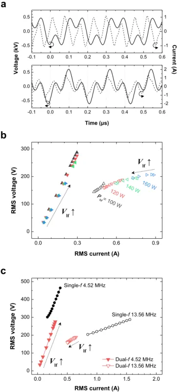
As a basic reference, we obtained the electrical and electron characteristics of the single-frequency argon dis-charges at 4.52 MHz and 13.56 MHz as presented in Fig. 1. The typical voltage and current waveforms are depicted in Fig. 1(a); the upper panel corresponds to 13.56 MHz, and the lower panel corresponds to 4.52 MHz. At both frequencies, the discharge current is slightly distorted from the sinusoidal shape. The origin of this distortion is the presence of high-harmonic components. These harmonics, observed also in symmetric discharge geometries, are known to be induced by the nonlinearity of the sheath in capacitive discharges13,14.
Figure 1(b) shows the root mean square (RMS) discharge voltage (VRMS) and current (IRMS), where the leftmost
and rightmost data points in each curve indicate the minimum and maximum discharge voltages or currents in the abnormal α-mode, respectively. At the voltage above the rightmost point, filaments were generated ran-domly inside the glow plasma. Although filaments were produced, a transition to the γ-mode (which induces plasma constriction and other significant changes in the plasma characteristics15,16) did not occur because the
dielectric barrier prevented the current density from exceeding a local maximum; thus, the applied voltage was sufficient to sustain discharge with coexistence of a uniform glow discharge and filaments. The positive slope of the IRMS-VRMS curves (or positive differential conductivities) indicates that the plasmas were in the abnormal glow
discharge mode. Compared with the 13.56-MHz discharge, the 4.52-MHz discharge occurred at a higher voltage and a lower current, and this frequency-dependence of electrical characteristics was also observed in our helium atmospheric-pressure plasmas7.
The time-averaged ne and Te in the bulk plasma are shown in Fig. 1(c) as a function of the rf power coupled to
the plasma [Prf=
∫
0τI t( )×V t t( )d /τ, where τ is the rf period]. The electron density monotonically increases with rf power at both frequencies, and this dependence ( ∝ ∝Prf Jb ne) can be easily explained using the simple resis-tor–capacitor (R–C) series circuit model considering the continuity of the conduction current Jb in the plasmabulk and the displacement current Js in the sheath. Figure 1(c) clearly demonstrates that the allowable operational
range of the abnormal α-mode depends on the driving frequency and the viability of ne and/or Te control.
Compared with the 13.56-MHz discharge, which is difficult to produce at low ne (i.e., ne > 1012 cm−3), the
4.52-MHz discharge is produced at a lower ne (4 × 10¹¹ to 9 × 1011 cm−3) and is prone to filament generation
because of the larger electron loss to electrodes caused by the larger electron oscillation amplitude and higher discharge voltage. The electron temperature of the 4.52-MHz discharge is linearly proportional to Prf, whereas that
of the 13.56-MHz discharge is almost constant at 2.5 eV. According to the previous paper17, the T
e of the bulk
plasma is expressed as Te∝E/σT, where σT is the total cross section of the atom, and E is the applied electric field.
For argon, σT is an increasing function of electron energy in the range 0.3–15.0 eV18; thus, the electrons are
pre-vented from gaining more energy from the electric field. Accordingly, σT in the denominator is a monotonically
increasing function of E in argon, which may result in an almost constant Te with the input power. However, the
increase in Te with increasing rf power in the 4.52-MHz discharge appears to be quite different from the trend.
One of the possible causes of this discrepancy is the difference in electron or ion dynamics in lower-frequency operations (or longer rf periods) compared to those at 13.56 MHz. Because of the long rf period (e.g., 4.52 MHz corresponds to approximately 221 ns), the electric field, which is built by the accumulated charges, becomes expo-nentially weakened, which results in electron depletion and extremely low Te values at certain rf phases (which
will be shown in the spatiotemporal evolution of neutral bremsstrahlung and Te). Thus, as the rf power (or
volt-age) is increased in low-frequency discharges (4.52 MHz in this work), this electron depletion period would be decreased, thereby resulting in an increase in time-averaged Te. The electron information given in Fig. 1(c) implies
that ne is primarily determined by Prf and can be controlled (40–50%) in single-frequency discharges, whereas Te
has a narrow variation range (<10%).
In the following, the results of the discharge produced by the combination of 4.52 MHz (hereafter referred to as ‘lf’) and 13.56 MHz (referred to as ‘hf’) are presented, where the latter is the third harmonic of 4.52 MHz. Typical waveforms of discharge voltage and current with 0° and 180° phase differences between the two fre-quencies are presented in the upper and bottom panels in Fig. 2(a), respectively. Because of the high discharge voltage amplitude with a 180° phase at certain rf phases, an easy transition from the glow to filamentary modes is observed at relatively low lf voltages (Vlf). Thus, the accessible operation window of the glow α-mode discharge is
narrow. Because of the narrow operation range and the lack of remarkable changes in either ne or Te in the case of
the 180° phase difference (not shown here), only discharges with a 0° phase difference are discussed further. The
IRMS versus VRMS plot for each frequency component is shown in Fig. 2(b), and these values are obtained from the
measured dual-frequency current and voltage waveforms using the fast Fourier transform. The data are acquired by increasing Vlf at each high-frequency input power (Phf) of 100, 120, 140, and 160 W in the entire abnormal
α-mode operation window. Therefore, the two ends of each curve represent the minimum and maximum volt-ages and currents in the abnormal α-mode discharge. In the figure, the solid (open) symbols shown in the left
(right) part of the figure denote the lf (hf) components. As indicated by the black arrows, the lf current mono-tonically increases as Vlf increases, whereas the hf components slightly decrease. Because the rf power coupling
changes continuously under variations in plasma impedance, the hf voltage and current components also change throughout the experiment despite Phf being fixed. As Phf increases from 100 to 160 W, the maximum achievable Vlf decreases from 287 to 175 V and the minimum allowable voltage decreases as the hf power increases. These
results indicate that Phf must be sufficiently high to sustain discharge at low Vlf.
To compare the electrical characteristics of the dual-frequency discharge with those of the single-frequency discharge, the Phf = 120 W case is re-plotted in Fig. 2(c) with the single-frequency results (denoted by circles) Figure 1. Electrical and electron characteristics of single-rf argon capacitive discharges. (a) Typical discharge
voltage and current waveforms of 13.56 MHz (top) and 4.52 MHz (bottom); (b) IRMS-VRMS characteristics of
single-rf-driven discharges at 13.56 MHz and 4.52 MHz; and (c) ne and Te as a function of rf power coupled to
the plasma. Data in b and c are shown as the mean ± s.d. for all panels; n = 5. The error bar of the x-axis data corresponds to the difference between the input rf power and dissipated rf power or IRMS.
www.nature.com/scientificreports/
presented in Fig. 1(b). The slopes of both the lf and hf components are more or less the same as those in the single-frequency cases. The R–C circuit model provides the relationship between the displacement current Id and
the sheath voltage Vs as Id = (2πfd) × CshVs, where Csh= .1 52ε0A d/ s, fd is the driving frequency, ε0 is the vacuum
permittivity, A is the plasma area, and ds is the sheath thickness. The curve of the lf component, which is shifted
toward the positive direction in the graph (a high discharge voltage with the same discharge current), indicates
Figure 2. Electrical characteristics of dual-rf argon capacitive discharges. (a) Dual-frequency waveforms of the
discharge voltage and current with 0° (top) and 180° (bottom) phase differences between the hf and lf voltage components. (b) VRMS-IRMS characteristics of the lf (solid symbols) and hf (open symbols) components with
a 0° phase difference and various Phf. (c) IRMS-VRMS characteristics of dual- and single-frequency capacitive
discharges. For clarity, data in b and c are only shown as the mean value for all panels (n = 5). The standard deviations of the y-axis data were <1% of the mean values.
that the sheath capacitance increases with the dual-frequency discharge compared with the single-frequency case. This result demonstrates that the time-averaged sheath thickness of the dual-frequency discharge is smaller than that of the 4.52-MHz single-frequency discharge because of the presence of the 13.56-MHz rf field, i.e., the plasma sheath and electron dynamics are coupled to both excitation frequencies.
The left and right panels of Fig. 3(a) present the measured wavelength-resolved emissivity (κ) in dual-frequency plasmas operating under the leftmost (Vlfmin) and rightmost (V
lfmax) conditions of Fig. 2(c) as well
as their ratio. As depicted, each spectrum is well fitted by the theoretically calculated κea, which is represented by Figure 3. Electron information in dual-rf argon capacitive discharges. (a) Measured emission spectra (black
scatters) with the theoretically calculated κea (red and blue lines) in the left panel, and the emissivity ratio of
the measurement (black) and calculation (green) in the right panel. (b) Electron density and temperature as a function of the percentage of the Vlf component. (c) Dual-frequency voltage waveforms at different Vlf. Data in
b are shown as the mean ± s.d.; n = 5. The error bar of the x-axis data corresponds to the difference between the input rf power and the dissipated rf power or voltage.
www.nature.com/scientificreports/
the red and blue solid curves. The fitting yielded Te = 2.5 eV with ne = 7.7 × 1011 cm−3 for the Vlfmin condition and
Te = 1.75 eV with ne = 1.4 × 1012 cm−3 for the Vlfmax condition. Because the spectral distribution of κea is
deter-mined by Te, differences in Te can be simply estimated via the ratio of the two spectra as shown in the right panel
of Fig. 3(a). The decrease in emissivity ratio, κ(Vlfmin)/ (κV )
lfmax, with increases in wavelength indicates that the Te
value at Vlfmin is higher than that at V
lfmax. The emissivity ratio of the measured spectra (black scatter) is consistent
with the ratio (green line) of the blue and red curves as plotted in the right panel of Fig. 3(a). Furthermore, the intensity ratio of the Ar I atomic lines below unity and the bremsstrahlung-fitting results indicate that the ne value
is higher at Vlfmax than that at V
lfmin. The results of the measured ne and Te are summarized in Fig. 3(b), which shows
that ne increases (by 82%) and Te decreases (by 35%) as Vlf is increased. One noticeable feature is that Te decreases
below the minimum Te with the 4.52-MHz single-frequency discharge when the lf component is introduced at an
amplitude greater than 40% of the discharge voltage. By comparing these findings with the results of single-rf excitation, we conclude that Te is mainly governed by the ratio of the lf and hf voltages in dual-frequency
discharges.
In the following, interpretations of the effect of lf power on the electron characteristics of dual-rf discharges are presented. First, the electron displacement caused by the electric field increases as Vlf increases. Consequently,
energetic electrons are driven out of the plasma bulk because of the thicker sheath, and these electrons are readily trapped within the sheath and lose their kinetic energy. Furthermore, more secondary electrons are emitted from the electrode surface because the ion bombardment energy at the electrodes increases with Vlf. These electrons
easily produce and supply new cold electrons into the plasma through electron-impact ionization. As a result, the time-averaged Te decreases and ne increases with increases in Vlf. Second, an intuitive description of electron
heating can be proposed based on the voltage waveform. According to a study on single-frequency discharges, electron heating occurs during the expansion and collapse of the sheath, thus revealing a spatial symmetric struc-ture in both electrodes19. The nonlinearity of the sheath dynamics and electron heating structure can be induced
by each frequency power in dual-frequency-driven discharges compared with those in the single-frequency case. As the fraction of Vlf is increased, the depth of the trough between the two local maxima in the dual-frequency
voltage waveform at certain rf phases (denoted by “2”) decreases as shown in Fig. 3(c), implying that the electric field strength decreases. As a result, electrons gain less energy in the “2” phase at both electrodes. The polarity of the electrodes no longer changes at these phases when the percentage of the Vlf component exceeds approximately
50%. In such cases, electron heating is suppressed in both phase “2” and phase “3” at both sheaths. Electron heat-ing is also suppressed in phases “1” and “4” but only durheat-ing sheath collapse (except for the electrode where sheath expansion occurs). Therefore, the spatiotemporal structure of electron heating is modified during one lf cycle, thereby substantially reducing the time-averaged Te with increasing Vlf.
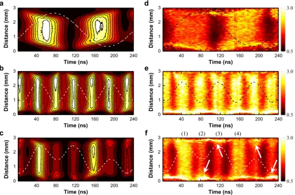
To verify the difference between the electron heating structures of single- and dual-frequency discharges, the spatiotemporal evolution of neutral bremsstrahlung and Te during one lf cycle (~221 ns) was investigated.
By following the approach described in the Methods section and our previous papers20,21 in detail, we acquired
nanosecond-resolved 514.5-nm and 632.8-nm continuum radiation images. The spatiotemporal profiles of the normalized neutral bremsstrahlung at 514.5 nm in single 4.52-MHz and 13.56-MHz discharges and in the dual-frequency discharge are shown in Fig. 4(a–c). Using the spatiotemporal profiles of neutral bremsstrahlung intensity at 514.5 nm and 632.8 nm, the phase dependence of Te in single- and dual-rf discharges was determined
as shown in Fig. 4(d–f). The temporal structures of κea and Te appeared similar because ne does not fluctuate with
the rf field in the bulk plasma, which has been shown experimentally and numerically20,22. Two bright structures
during one rf cycle appeared when the rf oscillating field amplitude reaches a maximum, and the expanding and collapsing sheaths were clearly observed near the electrodes in single-rf discharges as shown in Fig. 4(d,e). When
Vlf was introduced, Te decreased prominently at certain rf phases compared with that of the single 13.56-MHz
discharge. This experimental evidence was partly consistent with the intuitive analysis discussed in the foregoing paragraph. Asymmetric discharge structures were detected at 80 ns and 190 ns [see white arrows in Fig. 4(f)]. The localized electron heating near electrodes was caused by the electric field induced by space electrons accumulated during the sheath collapse phase. However, contrary to expectations, symmetric structures were still observed in phases “1” and “4” of the dual-frequency discharge as shown in Fig. 4(f).
This behavior is consistent with the numerical modeling results reported in the previous paper11. A
numer-ical investigation of the 13.56-MHz and 40.68-MHz dual-frequency helium capacitive discharges showed that the space- and phase-averaged ne increased by 76% and the Te decreased by 49% with a fixed power input
(0.5 W·cm−2) as the lf contribution varied from 0 to 50%11. In our case, even when the lf voltage increased, the
total dissipated power was approximately constant. This result implies that the electron kinetics in dual-rf plasmas is strongly influenced by the lf power rather than by the power density.
Conclusions
A dual-frequency operational approach was proposed to achieve the selective control of ion energy and density separately at low-pressure plasmas. Although the underlying principle of this technique is well established [ion energy (Ti) and ion density (ni) or flux coupled with low and high frequencies, respectively], ideal separate control
cannot always be achieved because of the complexity and nonlinear nature of low-pressure discharges. Notably, the mechanism underlying the individual control of ne and Te reported in this paper is not identical to that in the
case of ni and Ti in low-pressure discharges because of the different operational conditions. First, the electron
characteristics and heating structure in single-frequency discharges at atmospheric pressure are essentially differ-ent from those at low-pressure discharges. Furthermore, as clearly visualized in Fig. 4, collisional electron heating with a high frequency is spatiotemporally tailored by low-frequency power, and such a phenomenon is rarely observed in low-pressure discharges.
In summary, the electrical characteristics and electron information in single- and dual-rf argon capacitive dis-charges have been provided. In the single-rf discharge, a higher discharge current and ne, both of which increase
linearly with the input power, are observed with a higher-frequency excited discharge, whereas Te is not strongly Figure 4. Nanosecond-resolved visualization of electron heating. Spatiotemporal evolution of neutral
bremsstrahlung at 514.5 nm measured in a (a) 4.52-MHz frequency discharge, (b) 13.56-MHz single-frequency discharge, and (c) dual-single-frequency discharge, and spatiotemporal evolution of Te in a (d) 4.52-MHz
single-frequency discharge, (e) 13.56-MHz single-frequency discharge, and (f) dual-frequency discharge. The dashed lines indicate the measured discharge voltage waveforms.
Figure 5. Information regarding the experimental apparatus. Schematic of the plasma apparatus for generating
www.nature.com/scientificreports/
influenced by changes in rf power. Therefore, the achievable ne and Te ranges are restricted in the α-mode for
single-rf plasmas. However, with dual-rf excitation, both ne and Te are significantly influenced by the lf voltage
(82% increase in ne and 35% decrease in Te with increasing Vlf in the abnormal glow regime). The
spatiotempo-ral evolution of neutspatiotempo-ral bremsstrahlung and associated electron heating structures showed that electron heat-ing via ohmic heatheat-ing at the plasma-sheath boundary is suppressed at certain rf phases and electrons lose their kinetic energy via hf oscillations, which results in the spatiotemporal asymmetric structure of electron heating. Therefore, our experimental findings have revealed that ne and Te are independently coupled with the excitation
frequency in a dual-frequency-driven discharge. However, even if separate control of electron density and tem-perature cannot ideally be achieved, the results indicate that a dual-frequency operation allows a wide window of electron characteristics that can be accessed, thereby providing considerable reactivity and applicability. This result regarding electron kinetics in collisional rf discharges will provide a fundamental reference for further studies involving plasma characterization and applications.
Methods
Information regarding the plasma apparatus.
The present study was performed using a parallel-plate geometry, and a schematic of the setup is illustrated in Fig. 5. A detailed description of the experimental setup, which consists of a plasma chamber and a relevant optical emission spectroscopic diagnostic system, is available in our previous paper23. A 1-mm-thick alumina plate was placed on the bottom electrode to enlarge the operatingrange, and the gap distance between the bare upper electrode and the alumina plate was fixed at 3 mm throughout the experiment. Two separate power sources were used simultaneously to produce the dual-frequency-driven plasma: a RFPP RF10S power supply that delivered high-frequency sinusoidal power at 13.56 MHz and a com-bination of a signal generator (Agilent 33512B) and a rf amplifier (Amplifier Research 500A100A) that provided low-frequency sinusoidal power at 4.52 MHz. These two synchronized power systems were connected to the bottom electrode through resonant circuits used to block the other frequency. The phase difference between the hf and lf power was controlled by adjusting the phase delay of the trigger signal for the hf power at the signal generator. To produce single-frequency-driven plasmas, each of the aforementioned power sources was connected individually to the bottom electrode through an impedance-matching circuit. The discharge voltage and current were monitored using a high-voltage probe (Tektronix P6015A) and a DC-coupled current probe (Tektronix TCP202), respectively, connected to a wide-band oscilloscope (Tektronix TDS3012B). The ne and Te
of the plasma were estimated from the time-averaged continuum radiation originating from the electron-neutral atom bremsstrahlung. The spectrally resolved emissivity of plasma emission was measured using an absolutely calibrated collection optic system, which is identical to the setup described in our previous paper23.
Electron diagnostics based on electron-neutral atom bremsstrahlung.
Electron diagnostics basedon neutral bremsstrahlung was used in this work. Continuum radiation emitted from weakly ionized gases mainly originates from electron-neutral atom interactions, i.e., neutral bremsstrahlung, and the associated emis-sivity contains electron information23–26. Because the contributions of other continuum radiation sources,
electron-ion bremsstrahlung (κeiff) and recombination (κeifb), to the emissivity in the UV and visible range vary
with the driving conditions, particularly the gas pressure, the κea dominant conditions should be assured. A
sim-ple calculation using equations 1–3 in the previous paper23 with T
e = 3 eV, ne = ni, and wavelength-dependent
Biberman factors indicates that κeaκeiff+κeifb in the wavelength range of 200–900 nm when ne/na < 10−3,
which is the case for most low-temperature plasmas at subatmospheric-to-atmospheric pressure. One of crucial information on this diagnostic method is the electron energy distribution function (EEDF). In this work, the Maxwellian distribution, which is reasonable and acceptable in argon glow discharges at atmospheric pres-sure27,28, was used to determine the κ
ea value. For distributions other than Maxwellian, the κea value should be
carefully calculated with known EEDFs.
Nanosecond-resolved 2-D electron temperature measurement.
Because the spectraldistribu-tion of κea solely depends on Te (see Fig. 1 in ref.20), the electron temperature can be determined by fitting the
spectral distribution of the measured continuum radiation with that of the theoretically calculated κea. More
simply, the ratio of neutral bremsstrahlung intensities at two different wavelengths can be used to determine
Te without the full spectrum as described in our previous paper20. To measure the spatiotemporal evolution of
neutral bremsstrahlung and Te, the following technique was employed. The continuum radiation at two different
wavelengths was acquired using a combination of optical interference filters with ultra-narrow transmittances and center wavelengths of 514.5 nm and 632.8 nm and an intensified-CCD (iCCD) camera (Andor DH312T). Phase- and nanosecond-resolved sequential images of the continuum radiation at 514.5 nm and 632.8 nm were obtained with a gate width of 6 ns on the iCCD camera and an interval between two time-adjacent shots of 2 ns. All shots were acquired with a 1-s exposure time, and five shots were averaged to produce a single image. The 452-kHz trigger signal, which is 1/30 of 13.56 MHz, for the iCCD camera was provided using a signal generator (Agilent 33512B), and the signal was synchronized with the rf power supplies. A single shot was captured using the integrate-on-chip mode of the iCCD camera, during which charges were accumulated 4.52 × 10⁵ (452-kHz
gate signal × 1 s exposure time) times on the CCD. By integrating the emission profiles along the line of sight parallel to the electrodes, the spatiotemporal evolution of the continuum radiation was obtained as presented in Fig. 4, and the spatiotemporal evolution of Te was obtained from the ratio of neutral bremsstrahlung intensities at
514.5 nm and 632.8 nm. The inducible errors and expected uncertainty of this two color-based electron diagnos-tics were discussed in detail in our previous paper20.
Data availability.
The authors declare that the data supporting the findings of this study are available within the paper. All additional raw and derived data that support the plots within this paper and other findings of this study are available from the corresponding author upon reasonable request.References
1. Kim, H. C. & Lee, J. K. Mode transition induced by low-frequency current in dual-frequency capacitive discharges. Phys. Rev. Lett.
93, 085003 (2004).
2. Boyle, P. C., Ellingboe, A. R. & Turner, M. M. Electrostatic modelling of dual frequency rf plasma discharges. J. Phys. D: Appl. Phys.
37, 493–503 (2004).
3. Turner, M. M. & Chabert, P. Collisionless heating in capacitive discharges enhanced by dual-frequency excitation. Phys. Rev. Lett.
96, 205001 (2006).
4. Bruneau, B. et al. Strong ionization asymmetry in a geometrically symmetric radio frequency capacitively coupled plasma induced by sawtooth voltage waveforms. Phys. Rev. Lett. 114, 125002 (2015).
5. Shi, J. J. & Kong, M. G. Evolution of discharge structure in capacitive radio-frequency atmospheric microplasmas. Phys. Rev. Lett. 96, 105009 (2006).
6. Iza, F., Lee, J. K. & Kong, M. G. Electron kinetics in radio-frequency atmospheric-pressure microplasmas. Phys. Rev. Lett. 99, 075004 (2007).
7. Moon, S. Y., Kim, D. B., Gweon, B. & Choe, W. Driving frequency effects on the characteristics of atmospheric pressure capacitive helium discharge. Appl. Phys. Lett. 93, 221506 (2008).
8. Shi, J. J. & Kong, M. G. Expansion of the plasma stability range in radio-frequency atmospheric-pressure glow discharges. Appl. Phys.
Lett. 87, 201501 (2005).
9. Waskoenig, J. & Gans, T. Nonlinear frequency coupling in dual radio-frequency driven atmospheric pressure plasmas. Appl. Phys.
Lett. 96, 181501 (2010).
10. Atanasova, M., Sobota, A., Brok, W., Degrez, G. & van der Mullen, J. J. A. M. Driving frequency dependence of capacitively coupled plasmas in atmospheric argon. J. Phys. D: Appl. Phys. 45, 335201 (2012).
11. O’Neill, C., Waskoenig, J. & Gans, T. Tailoring the nonlinear frequency coupling between odd harmonics for the optimisation of charged particle dynamics in capacitively coupled oxygen plasmas. Appl. Phys. Lett. 101, 154107 (2012).
12. Kawamura, E., Lieberman, M. A., Lichtenberg, A. J., Chabert, P. & Lazzaroni, C. Particle-in-cell and global simulations of α to γ transition in atmospheric pressure Penning-dominated capacitive discharges. Plasma Sources Sci. Technol. 23, 035014 (2014). 13. Lieberman, M. A. Dynamics of a collisional, capacitive RF sheath. Ieee Trans. Plasma Sci. 17, 338–341 (1989).
14. Dvořák, P. Modelling of electric characteristics of capacitively coupled discharges including nonlinear effects of sheaths. Plasma
Sources Sci. Technol. 22, 045016 (2013).
15. Moon, S. Y., Rhee, J. K., Kim, D. B. & Choe, W. α, γ, and normal, abnormal glow discharge modes in radio-frequency capacitively coupled discharges at atmospheric pressure. Phys. Plasmas 13, 033502 (2006).
16. Moon, S. Y., Kim, D. B., Rhee, J. K., Gweon, B. & Choe, W. Capacitive discharge mode transition in moderate and atmospheric pressure. Curr. Appl. Phys. 9, 274–277 (2009).
17. Li, S.-Z., Lim, J.-P., Kang, J. G. & Uhm, H. S. Comparison of atmospheric-pressure helium and argon plasmas generated by capacitively coupled radio-frequency discharge. Phys. Plasmas 13, 093503 (2006).
18. Golden, D. E. & Bandel, H. W. Low-energy e−−Ar total scattering cross sections: The ramsauer-townsend effect. Phys. Rev. 149, 58 (1966).
19. Liu, D. W., Iza, F. & Kong, M. G. Electron heating in radio-frequency capacitively coupled atmospheric-pressure plasmas. Appl. Phys.
Lett. 93, 261503 (2008).
20. Park, S., Choe, W., Moon, S. Y. & Yoo, S. J. Spatio-temporally resolved electron temperature in argon radio-frequency capacitive discharge at atmospheric pressure. Plasma Sources Sci. Technol. 24, 032006 (2015).
21. Park, S., Choe, W., Kim, H. & Park, J. Y. Continuum emission-based electron diagnostics for atmospheric pressure plasmas and characteristics of nanosecond-pulsed argon plasma jets. Plasma Sources Sci. Technol. 24, 034003 (2015).
22. Balcon, N., Hagelaar, G. J. M. & Boeuf, J. P. Numerical model of an argon atmospheric pressure RF discharge. Ieee Trans. Plasma Sci.
36, 2782–2787 (2008).
23. Park, S., Choe, W., Moon, S. Y. & Park, J. Electron density and temperature measurement by continuum radiation emitted from weakly ionized atmospheric pressure plasmas. Appl. Phys. Lett. 104, 084103 (2014).
24. Park, J., Henins, I., Hermann, H. W. & Selwyn, G. S. Neutral bremsstrahlung measurement in an atmospheric-pressure radio frequency discharge. Phys. Plasmas 7, 3141–3144 (2000).
25. Taylor, R. L. & Caledonia, G. Experimental determination of the cross-sections for neutral Bremsstrahlung: I. Ne, Ar and Xe. J.
Quantum Spectrosc. Radiat. Transter 9, 657–679 (1969).
26. Burm, K. T. A. L. Continuum radiation in a high pressure argon-mercury lamp. Plasma Sources Sci. Technol. 13, 387–394 (2004). 27. Zhang, Z. L., Lim, J. W. M., Nie, Q. Y., Zhang, X. N. & Jiang, B. H. Electron heating and mode transition in dual frequency
atmospheric pressure argon dielectric barrier discharge. AIP Advances 7, 105313 (2017).
28. Desjardins, E. et al. Time-resolved study of the electron temperature and number density of argon metastable atoms in argon-based dielectric barrier discharges. Plasma Sources Sci. Technol. 27, 015015 (2018).
Acknowledgements
This work was supported by the R&D Program of ‘Plasma Advanced Technology for Agriculture and Food (Plasma Farming)’ through the National Fusion Research Institute of Korea (NFRI) funded by the government of Korea. This work was also supported by Research and Business Development Program through the Korea Institute for Advancement of Technology (KIAT) funded by the Ministry of Trade, Industry and Energy (MOTIE) (Grant number: N0002038).
Author Contributions
S.P. and W.C. conceived the research. S.P. conducted all the experiments, and all the authors interpreted the results. S.P. prepared the manuscript, and all the authors contributed to the compilation and review of the manuscript.
Additional Information
Competing Interests: The authors declare no competing interests.
Publisher's note: Springer Nature remains neutral with regard to jurisdictional claims in published maps and
www.nature.com/scientificreports/
Open Access This article is licensed under a Creative Commons Attribution 4.0 International
License, which permits use, sharing, adaptation, distribution and reproduction in any medium or format, as long as you give appropriate credit to the original author(s) and the source, provide a link to the Cre-ative Commons license, and indicate if changes were made. The images or other third party material in this article are included in the article’s Creative Commons license, unless indicated otherwise in a credit line to the material. If material is not included in the article’s Creative Commons license and your intended use is not per-mitted by statutory regulation or exceeds the perper-mitted use, you will need to obtain permission directly from the copyright holder. To view a copy of this license, visit http://creativecommons.org/licenses/by/4.0/.