MBD
와
FEM
을 이용한 단일윤축 모델의 충돌 후 탈선거동의 해석
Analysis of Collision-induced Derailments of a Wheel-set Model
Using MBD and FEM Simulation
이준호
*
구정서Jun-Ho Lee Jeong-Seo Koo
ABSTRACT
In this paper, a theoretical formulation of a simplified wheel-set model for collision-induced derailments was
evaluated by numerical simulations for the wheel-climb derailment and wheel-lift derailment types. The derailment
types were classified into the wheel-climb derailment and the wheel-lift derailment according to the friction force
direction of the wheel-flange. The wheel-climb derailment type was classified into Climb-up, Climb/Roll-over, and
Roll-over-C, and wheel-lift derailment type was classified into Slip-up, Slip/Roll-over and Roll-over-L. To verify
the theoretical equations derived for the wheel-climb derailment and the wheel-lift derailment, dynamic simulations
using RecurDyn of Functionbay and Ls-Dyna of LSTC were performed and compared for some examples. The
derailment predictions of the suggested theoretical formulation were in good agreement with those of the numerical
simulations. The direction of the frictional force between the wheel-flange and the rail can be well predicted using
the suggested derailment formulation at a initial derailment.
1. 서 론 열차는 많은 승객과 물자를 운반하는 대형운송수단으로 최근 국내에서는 최고속도 350 km/h 인 KTX-산천이 운행 중이고 열차는 점점 고속화가 되어 가고 있다. 열차가 고속화가 됨에 따라 반대로 안전의 측면에서는 위험요인을 증가시키고 있다. 특히 열차가 충돌이나 탈선이 발생하면 많은 인명과 재산에 큰 피해를 입일 수 있다. 그래서 현재 국내에서는 철도차량의 충돌과 탈선으로 인해 일어나는 사고들을 예방하기 안전규정을 정해놓았다.[1] 충돌 안전설계와 안전규정평가를 위해 실제차량을 이용한 충돌시험이 필요하지만 이는 많은 시간과 비용이 필요로 하고 비효율적이므로, 이에 대체 방안으로 가상시험모델을 이용하여 간접적인 평가방법 을 제시하였다.[2~3] 최근 연구에서 철도차량의 충돌 후 탈선 거동을 예측하는 이론적인 방법을 제안되었고[4-6], 충돌 후 탈선 유형을 본 논문에서 제시한 것과 같이 타고오름 탈선과 미끄러져 오름 탈선으로 분류하여 제안 하였다.[7,8] 그러나 이 연구에서는 Functionbay사의 RecurDyn 만을 사용하여 단일윤축의 동역학 시뮬 레이션으로 증명하였다. 본 논문에서는 LSTC사의 Ls-Dyna 유한요소모델과 Functionbay사의 RecurDyn 모델을 사용하여 FEM 및 MBD 시뮬레이션을 통해 충돌 후 탈선 거동을 비교하고 [참고문헌 7]에서 제안된 이론식의 타당성을 평가한다.
2. 동역학 시뮬레이션을 이용한 충돌 후 탈선 거동예측 검증
그림 1. A RecurDyn model vs. a Ls-Dyna model
본 논문에서는 Functionbay사의 ReucerDyn과 LSTC사의 Ls-Dyna를 사용하여 동역학 시뮬레이션을 통해 타고오름 탈선 이론식과 미끄러져 오름 탈선 이론식을 검증하고 탈선거동을 비교한다.[9~10] 그 림 1은 RecurDyn 모델과 Ls-Dyna 모델을 보여준다.
2.1 RecurDyn과 Ls-Dyna을 이용한 Climb-up에 대한 탈선거동 비교 검증
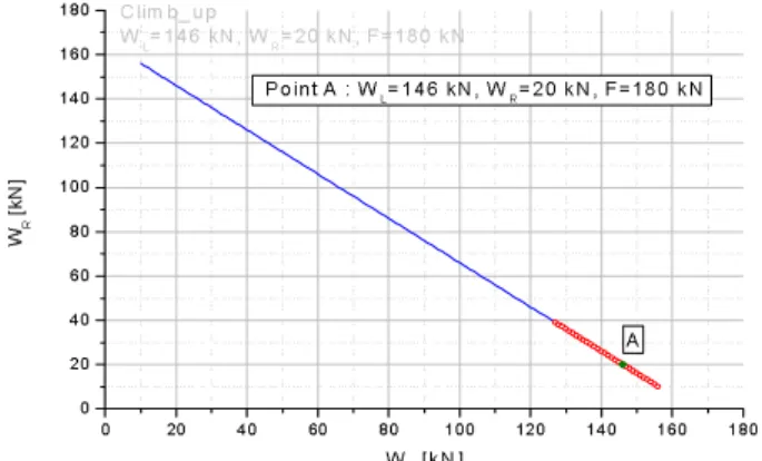
타고오름 탈선 검증을 위해 사용된 단일 윤축모델은 단순 플랜지 각이 (플랜지 여각 )와 쿨롱 마찰 계수를 0.1로 적용한다. 그림 2와 같이 특정 수평하중 값 (Climb-up 상태에서 180 kN)에 대해
탈선유형의 발생 조건을 만족하는 수직하중의 범위 중에서 하나의 값( )을 선
정하여 사용한다.
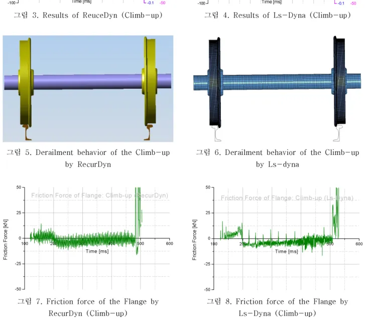
그림 3, 4는 그림 2의 Climb-up에 해당하는 조건들을 입력하여 RecurDyn 모델과 Ls-Dyna 모델에
서 얻은 접촉력 , 플랜지 접촉면을 따라 이동한 타고오름 변위 , 윤축의 회전각을 나 타낸 것이다. RecurDyn에서는 Climb-up 조건들을 을 191 ms부터 505 ms까 지 만족하고, Ls-Dyna에서는 180 ms부터 530 ms까지 만족한다. 그림 5, 6은 각각 RecurDyn 모델과 Ls-Dyna의 탈선거동을 나타내고 있다. 그리고 그림 7, 8은 두 모델의 플랜지와 레일사이의 마찰력 방 향을 살펴보면 초기에는 타고오름 탈선이 발생함을 볼 수 있다. 0 20 40 60 80 100 120 140 160 180 0 20 40 60 80 100 120 140 160 180 Clim b_up WL=146 kN, WR=20 kN, F=180 kN WR [k N ] WL [kN] Point A : WL=146 kN, WR=20 kN, F=180 kN A
그림 2. Sampling data for the Climb-up (F=180kN)
0 100 200 300 400 500 600 -100 0 100 200 300 400 500 600 Fo rce [k N] Time [ms] RL RR RF -0.1 0.0 0.1 0.2 0.3 0.4 0.5 0.6 θ Ro tat ion A ng le [ra d] -50 0 50 100 150 200 250 300 505 ms dR Climb_up (RecurDyn) WL=146 kN, WR=20 kN, F=180 kN Di sp lac em en t [m m] Climb_up 191 ms
그림 3. Results of ReuceDyn (Climb-up)
-1000 100 200 300 400 500 600 0 100 200 300 400 500 600 530 ms 180 ms Climb_up Climb_up (Ls-Dyna) WL=146 kN, WR=20 kN, F=180 kN Fo rce [k N] Time [ms] RL RR RF -0.1 0.0 0.1 0.2 0.3 0.4 0.5 0.6 θ Ro tat ion A ng le [ra d] -50 0 50 100 150 200 250 300 dR Di sp lac em en t [m m]
그림 4. Results of Ls-Dyna (Climb-up)
그림 5. Derailment behavior of the Climb-up by RecurDyn
그림 6. Derailment b ehavior of the Climb -up by Ls-dyna 100 200 300 400 500 600 -50 -25 0 25 50
Friction Force of Flange: Climb-up (RecurDyn)
Fr ic tio n Fo rc e [k N ] Time [ms]
그림 7. Friction force of the Flange b y RecurDyn (Climb-up) 100 200 300 400 500 600 -50 -25 0 25 50
Friction Force of Flange: Climb-up (Ls-Dyna)
Fr ic tio n Fo rc e [k N ] Time [ms]
그림 8. Friction force of the Flange by Ls-Dyna (Climb-up)
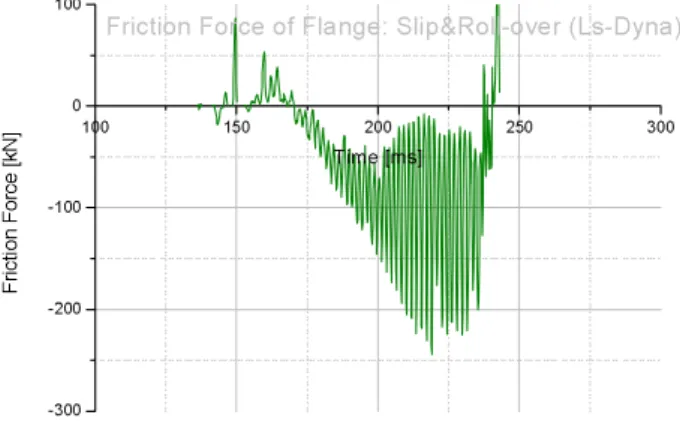
2.2 RecurDyn과 Ls-Dyna을 이용한 Slip/Roll-over에 대한 탈선거동 비교 검증
미끄러져 오름 탈선 검증을 위해 사용된 단일 윤축모델은 단순 플랜지 각이 (플랜지 여각 )와 쿨롱마찰 계수를 0.2로 적용한다. 그림 9와 같이 특정 수평하중 값 (Slip/Roll-over 상태에서 600 kN)
을 나타낸 것이다. RecurDyn에서는 Slip/Roll-over 조건들을 을 187 ms부터 243 ms까지 만족하고, Ls-Dyna에서는 191 ms부터 242 ms까지 만족한다. 그림 12, 13은 RecurDyn 모델과 Ls-Dyna 모델의 탈선거동을 나타낸다. 그리고 그림 14, 15는 두 모델의 플랜지와 레일사이의 마찰력 방향을 살펴보면 미끄러져 오름 탈선에 해당됨을 볼 수 있다. 0 20 40 60 80 100 120 140 160 180 0 20 40 60 80 100 120 140 160 180 Slip&roll_over WL=136 kN, WR=30 kN , F=600 kN A WR [k N ] WL [kN ] Point A : WL=136 kN , WR=30 kN , F=600 kN
그림 9. Sampling data for the Slip/roll-over (F=600kN) 0 100 200 300 400 500 -300 0 300 600 900 1200 1500 Fo rce [k N] Time [ms] RL RR RF -0.1 0.0 0.1 0.2 0.3 0.4 0.5 θ Ro tat ion A ng le [ra d] -100 0 100 200 300 400 500 243 ms Slip&Roll_over (RecurDyn) WL=136 kN, WR=30 kN, F=600 kN dR Di sp lac em en t [m m] Slip&Roll_over 187 ms
그림 10. Results of RecurDyn (Slip/Roll-over)
-3000 100 200 300 400 500 0 300 600 900 1200 1500 Fo rce [k N] Time [ms] RL RR RF -0.1 0.0 0.1 0.2 0.3 0.4 0.5 θ Ro tat ion A ng le [ra d] -100 0 100 200 300 400 500 242 ms 191 ms Slip&Roll_over Slip&Roll_over (Ls-Dyna) WL=136 kN, WR=30 kN, F=600 kN dR Di sp lac em en t [m m]
그림 11. Results of Ls-Dyna (Slip/Roll-over)
그림 12. Derailment behavior of the Slip/Roll-over by RecurDyn
그림 13. Derailment behavior of the Slip/Roll-over by Ls-Dyna
100 150 200 250 300 -300 -200 -100 0 100
Friction Force of Flange: Slip&Roll-over (RecurDyn)
Fr ic tio n Fo rc e [k N ] Time [ms]
그림 14. Friction force of the Flange by RecurDyn (Slip/Roll-over) 100 150 200 250 300 -300 -200 -100 0 100
Friction Force of Flange: Slip&Roll-over (Ls-Dyna)
Fr ic tio n Fo rc e [k N ] Time [ms]
그림 15. Friction force of the Flange by Ls-Dyna (Slip/Roll-over)
3. 결 론
본 논문에서는 충돌 후 탈선유형을 타고오름 탈선은 Climb-up, Climb/roll-over, Roll-over-C로 분 류하고, 미끄러져 오름 탈선은 Slip-up, Slip/roll-over, Roll-over-L로 분류하였다. 충돌 후 탈선유형 들을 이론적으로 분류하고 강체동역학 및 유한요소 시뮬레이션으로 다음과 같은 결과를 얻었다. - 철도차량의 충돌 후 탈선거동을 예측하기 위해 이론적으로 탈선유형들을 나누고 단일 윤축과 레일 의 접촉을 고려하여 강체동역학 및 유한요소 시뮬레이션을 통해 타당성을 입증하였다. - 단일윤축 이론 모델의 탈선 거동들의 검증해석을 동역학 시뮬레이션인 RecurDyn과 Ls-Dyna의 결 과와 비교하여 일치한 결과를 얻었다. - 타고오름 탈선과 미끄러져 오름 탈선 중 한 개만 발생하거나 동시에 발생할 수 있고, 동시에 발생 하는 경우는 플랜지 마찰력이 탈선 진행 중에 방향이 바뀐다. 참고문헌
1.
국토해양부, “
철도차량 안전기준에 관한 규칙”,
국토해양부고시 제2010-637
호, 2010.
2.
김거영,
조현직,
구정서,
권태수, “
동력집중식 고속열차의 충돌안전도 표준설계 가이드라인 도출”,
한 국자동차공학회논문집, 16
권, 6
호, pp.157-167, 2008.
3.
김거영,
조현직,
구정서, “
동력분산형 차세대 고속전철의 충돌안전도 개념설계 연구”,
한국철도학회논 문집, 11
권, 3
호, pp.300-310, 2008.
4.
조현직, “
가상시험모델을 이용한 충돌 후 탈선거동 예측 용 차륜-
레일 모델연구”,
공학박사학위논문,
한국,
서울과학기술대학교, 2010.
5. Hyun Jik Cho and Jeong Seo Koo, "A Method to Predict the Derailment of Rolling Stock due to Collision
Using a Theoretical Wheelset Derailment Model", Multibody System Dynamics, August 2011.
6. Hyun Jik Cho and Jeong Seo Koo, " A numerical study of the derailment caused by collision of a rail
vehicle using a virtual testing model", Vehicle System Dynamics, April 2011.
7.
최세영, “
열차의 충돌 후 탈선거동을 예측하기 위한 단일윤축 탈선 이론모델 개발”,
공학석사학위논문
,
한국,
서울과학기술대학교, 2011.
기 호
: Vertical axle load applied by the left suspensions
: Vertical axle load applied by the right suspensions
: lateral force of the suspensions group in each wheel-set : Contact force between the left wheel tread and the rail
: Contact force between the right wheel tread and the rail
: Contact force between the right wheel flange and the rail : Displacement of the right wheel along the flange slope
: Rotation angle of the wheel-set
![그림 9. Sampling data for the Slip/roll-over (F=600kN) 0 100 200 300 400 500 -3000 30060090012001500Force [kN] Time [ms] RL RR RF -0.10.00.10.20.30.40.5θ Rotation Angle [rad] -1000100200300400500243 msSlip&Roll_over (RecurDyn)WL=136 kN, WR=30 kN,](https://thumb-ap.123doks.com/thumbv2/123dokinfo/4986692.55974/4.892.283.618.250.459/그림-sampling-force-rotation-angle-msslip-roll-recurdyn.webp)