1. INTRODUCTION
Recently, Internet technology makes us travel all over the world to get valuable information. It provides us with not only fruitful infinite information to help to connect all the resources together, but also time saving to operate very remotely located plants. Internet has become a must use tool in our life for transferring data from one location to the other.
The area of an internet-based application contributes to unify the global world in terms of the business such as internet-based conferences, internet-based surgical operations, internet-based global meetings, internet-based projects, and so on.
In a control point of a view, Internet technology gives us feasible opportunities to control and operate remotely located systems. Specially, in a control system area, Internet plays a very important role as a communication channel as well as an operation channel. Examples of successful internet-based control applications have been reported in the literature [1-6]. Remote treatment of patients without visiting them has been successfully conducted. Remote mobile robot controls through the Internet have also been successfully performed. Specially, for control education, there have been many efforts to implement educational systems [1]. In addition, the concept of the internet is evolved to the ubiquitous network. Ubiquitous network helps our living environment to be self-monitored and automated. However, it is yet to be developed for practical uses.
Still the internet is the major tool to connect remotely located system even though it has a defect of time delay of transferring data in bi-directional communication channels. There have been many efforts to implement real time control based on the internet [7, 8]. In most of internet based control applications, simple linear control algorithms such as PD, PI or PID control methods are used to achieve fast computational time under the presence of time delay. It is known that linear controllers do not perform well for the nonlinear systems. For nonlinear systems, advanced control algorithms or intelligent control algorithms are required. Fuzzy and neural network control methods have been proved to work well for complicated nonlinear systems.
In this paper, an intelligent control method of using neural network is implemented to control a dynamical system
through the internet. Neural network is known to require fast computational time for updating internal weights to learn in every sampling time. This requires massively parallel computation of the fast computing hardware device. In our previous researches, we have developed the neural network control hardware using a DSP board and an FPGA chip [9]. Its performance has been tested for nonlinear system control. For the online learning and control, the reference compensation technique (RCT) has been implemented. The RCT has been proved to work well for controlling nonlinear systems such as inverted pendulum, robot manipulators, mobile robots, and aerial vehicles [10,11].
Since this implementation is targeted for a part of advanced control education, the feasibility of application is tested. Using the intelligent control hardware, experiments of controlling systems remotely are conducted through the internet.
2. SYSTEM CONFIGURATION
2.1 Overall structureThe overall structure is shown in Fig. 1. The whole system consists of a dynamical system unit, a PC, and an intelligent control hardware. In a PC, menu driven GUI for user’s convenience has been designed. The dynamical system unit is a DC motor. The intelligent control hardware includes a DSP, FPGA, a network communication module, and a motor driver. All of the necessary modules such as dada communication, encoder counter, a decoder for command for control is designed in an FPGA device.
Fig.1 Overall structure
Development of a Remotely Controlled Intelligent Controller for Dynamical
Systems through the Internet
Sungsu Kim* and Seul Jung**
* Department of Mechatronics Engineering, Chungnam National University, Daejeon, Korea (Tel : +82-42-821-7232; E-mail: [email protected])
**Department of Mechatronics Engineering, Chungnam National University, Daejeon, Korea (Tel : +81-42-821-6876; E-mail: [email protected])
Abstract: In this paper, an internet based control application for dynamical systems is implemented. This implementation is maily targeted for the part of advanced control education. Intelligent control algorithms are implemented in a PC so that a client can remotely access the PC to control a dynamical system through the internet. Neural network is used as an on-line intelligent controller. To have on-line learning and control capability, the reference compensation technique is implemented as intelligent control hardware of combining a DSP board and an FPGA chip. GUIs for a user are also developed for the user’s convenience. Actual experiments of motion control of a DC motor have been conducted to show the performance of the intelligent control though the internet and the feasibility of advanced control education.
2.2 Network communication module
A network communication module handles actual communication between a PC server and a client computer. The block diagram of a network communication module is shown in Fig. 2. The corresponding hardware has been developed and it is also shown in Fig. 3.
Fig.2 Block diagram of network communication module
Fig.3 Network communication module
3. INTELLIGENT CONTROL
3.1 Neural network control algorithmNeural network is used in the control loop as a compensator. In the control structure, a dynamical system is controlled by a PID controller as a main controller. Since there are tracking errors due to uncertainties, neural network outputs are added to the reference trajectories to modify the actual torque to compensate for uncertainties in the dynamical system as shown in Fig.4.
Fig.4 Neural network control structure The output error is formed as
θ
θ
−
=
de
(1)where
θ
d is a desired angle andθ
is an actual angle. A PID controller output is defined as3 2 1 ) ( ) ( ) (
φ
φ
φ
I D P D I P k k k t e k dt t e k t e k u + + + + + =∫
&(2)
Neural network outputs are defined as
3 2 1
φ
φ
φ
I D Pk
k
k
+
+
=
Φ
(3)Iff(
θ
,θ
&,θ
&&)is the system dynamics, equations (1) and (2) can be represented as follows:Φ
−
=
+
+
k
∫
edt
k
e
&
f
(
θ
,
θ
&
,
θ
&&
)
e
k
P I D (4)3.2 Neural network structure
For a nonlinear function at a hidden layer and an output layer we have used a hyperbolic tangent function as
) exp( 1 ) exp( 1 ) ( x x x f − + − − = (5)
For dynamical system control, a general purposed feed-forward neural network is also used, but a different number of units are used. The numbers of an input layer, a hidden layer, and an output layer are 3, 6, 3 respectively.
Fig.5 Neural network structure 3.3 Neural network learning
Since we are doing on-line learning and control, selecting the training signal is very important. If the left side of (4) becomes zero, then Φ≅ f(
θ
,θ
&,θ
&&). This means that inverse dynamics control can be achieved. So here we define the training signal of neural network ase
k
dt
e
k
e
k
v
=
P+
I∫
+
D&
(6)The objective function is defined as
2
2 1
v
E= (7)
Differentiating (7) with respect to weight, we have
w v w v v w v v E w E ∂ Φ ∂ − = ∂ ∂ = ∂ ∂ ∂ ∂ = ∂ ∂ (8) Here, we have
w
K
w
K
w
K
w
P I D∂
∂
+
∂
∂
+
∂
∂
=
∂
Φ
∂
φ
1φ
2φ
3 (9)The update equation in back propagation algorithm is
) 1 ( ) ( +∆ − ∂ ∂ = ∆ v wt w t w
η
ψ
(10) ) ( ) ( ) 1 (t wt wt w + = +∆ (11)3.4 Neural network control hardware
The actual intelligent control hardware has been developed as shown in Fig. 6 and 7. The controller consists of a DSP board and an FPGA chip. A DSP is used for the fast computing of neural network learning and an FPGA is used for other necessary modules. Detailed explanations of the hardware can be found in the previous paper [10].
Fig.6 Block diagram of neural network control hardware
Fig.7 Neural network control hardware
4. GUI
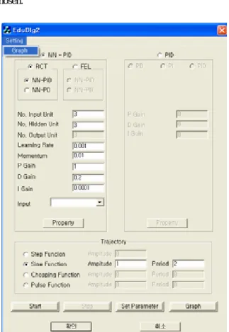
To access the control of a dynamical system easily, for user’s convenience, GUI has been developed. GUI has three parts: a control parameter selection part, a neural network parameter selection part, and an output plotting part. Fig.8 shows the window of the overall menu panel. Control methods can be selected either a PID control or a neural network control. It also provides two kinds of neural network control methods, the reference compensation technique and the feedback error learning method. Once you choose your control method, the following control parameters can be selected such as gains for PID controllers and learning rates, momentum constants for the neural network.
After selecting control parameters and neural control method, neural network is designed as shown in Fig.9. Control block diagram figure helps a user to understand the control structure and to select neural network parameters easily.
Different types of input pattern of neural network can be
chosen.
Fig.8 GUI of selecting parameters for controllers
Fig.9 GUI of selecting parameters of neural network
Fig. 10 shows the window of trajectory selection. Step, sine, and pulse function can be selected with an amplitude and a period.
Fig.10 GUI of selecting trajectory
In Fig.11, a user can choose output plots up to three. The corresponding plots are shown in Fig. 12.
Fig.11 GUI of plot command
Fig.12 GUI of plot window
5. EXPERIMENTAL RESULTS
For the actual experiment, a dc motor as a dynamical system is tested. A sinusoidal function trajectory is given to the system to follow and then the tracking results are plotted. To show the superiority of a neural network controller over a PID controller two experiments are conducted and both results are compared.
It looks like both a PID controller and a neural network controller work well as shown in Fig. 13 and 14. However, we clearly see from the error plots that the tracking error of neural network controller is less than 10 times that of a PID controller.
Fig.13 Tracking response of a PID controller
Fig.14 Tracking response of neural network controller
6. CONCLUSIONS
This paper presented the implementation of internet based intelligent control for a dynamical system. Hardware for internet communication and an intelligent controller have been developed. Even though massive calculation time is required for neural network learning, the controller successfully controlled the system through the internet. GUIs are also designed for user’s convenience. Actual experiments of controlling a DC motor remotely have been successfully conducted. Time delay problem in the internet has not been considered at this time.
ACKNOWLEDGMENTS
This research has been supported by the contract of KOSEF/KRF 05-2003-000-10389-0 in Korea. The authors would like to thank for their kind financial support.
REFERENCES
[1] N. Swamy, O. Kuljaca, F. L. Lewis, “Internet-based Educational Control Systems Lab Using NetMeeting”, pp. 145-151, IEEE Trans. on Education, May 2002
[2] L. Ngai, W. S. Newman, V. Liberatore, “An Experiment in Internet-Based, Human-Assisted Robotics”, pp. 2190-2195, IEEE Conf. on Robotics and Automations, 2002
[3] J. W. Park, J. M. Lee, “Transmission modeling and simulation for Internet-based control”, 2001. IECON '01.
The 27th Annual Conference of the IEEE Industrial Electronics , Volume: 1 , 29 Nov.-2 Dec. 2001
Pages:165 - 169 vol.1
[4] S. H. Yang, L. S. Tan, X. Chen, ”Requirements specification and architecture design for Internet-based control systems”, 26th Annual International Computer
Software and Applications Conference, pp. 75-80 Aug.
2002
[5] N. S. Liang, L. C. Fu, C. L. Wu, “An integrated, flexible, and Internet-based control architecture for home automation system in the Internet era”, IEEE
International Conference on Robotics and Automation,
pp. 1101-1106, Volume: 2 , 11-15 May 2002
[6] K. Yeun and J. Huang, “Development of the Internet-based control experiment”, IEEE Conf. on
Decision and Control, pp. 2809-2814, 2001
[7] S. Jung, P. W. Jeon, and H. T. Cho, “Interface Between robot and human: application to boxing robot”, IFAC
International Conf. on Mechatronics Systems, pp.
851-856, 2002
[8] S. Jung and P. W. Jeon, “Teleoperated control of mobile robot using exoskeleton-type motion-capturing device through wireless communication”, IEEE/ASME
Advanced Intelligent Mechatronics, pp. 1107-1112,
2003
[9] H. T. Cho and S. Jung, “Neural Network Position Control of an Inverted pendulum by an X-Y table robot”, IEEE IROS, pp. 1210-1215, 2003
[10] S. S. Kim and S. Jung, “Hardware Implementation of a real time neural network controller with a DSP and an FPGA”, IEEE ICRA, pp. 4639-4644, 2004
[11] S. Jung and D. H. Song, “Neural Network Compensation Technique for Standard PD-Like Fuzzy Controlled Nonlinear Systems”, IEEE CDC, pp. 698-703, 2004