http://dx.doi.org/10.11142/jicems.2014.3.4.379 379 Journal of International Conference on Electrical Machines and Systems Vol. 3, No. 4, pp. 379~382, 2014
The Influence of Stator Pole Shape and Its Arrangements on
Cogging Torque for Double-sided AFPM Generator
Chang-Eob Kim *, Joong-Keun Jang *, and Sung-Jun Joo **
Abstract
— In this paper, the cogging torques were calculated for 1kw double-sided axial flux permanent magnet (AFPM) generator with different stator core pole arrangements. The generator is composed of 18 stator pole and 24 rotating field magnets on each side. The cogging torques of the generator with three types of arrangements of stator poles were calculated using 3D finite element method and the optimum core shape was determined to minimize the cogging torque.Keywords:
AFPM generator, cogging torque, Stator core position, Different magnet pitch1. Introduction
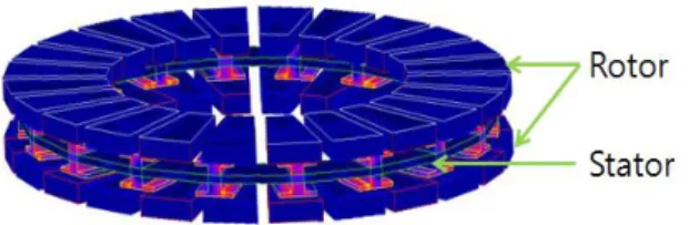
The axial flux permanent magnet (AFPM) machines have many advantages compared to the radial flux permanent magnet (RFPM) machines, including high power density, and better ventilation and cooling. The AFPM machine is generally the more suitable choice for high frequency or low speed operations because of its larger outer diameter than that of the RFPM machine [1]-[3]. However, there still remains the problem of the cogging torque, and many researches have been conducted in order to find ways to decrease it [4]-[6]. In this study, we present the influence of the shapes and arrangements of the stator core pole on cogging torque of a double-sided AFPM generator. Fig. 1 shows an analysis model of a double-sided AFPM generator, which is composed of 18 poles of stator cores, and 24 poles of rotor magnets. Here, we calculated the cogging torques of the generators with three types of arrangements of stator poles, using 3D finite element method. Also, the optimum core shape was utilized to minimize the cogging torque.
2. AFPM Generator and Cogging Torque
Fig. 2 shows the stator pole arrangements of AFPM generator with different positions of upper and lower pole, where τp, τα are pole pitch and pole difference, respectively.
We investigated the influence of the stator pole and its
arrangement on the cogging torque.
Fig. 1. Analysis model of 1kw AFPM generator.
(a) AFPM machine (b) Stator pole arrangement Fig. 2. Stator pole arrangements of AFPM machine. 2.1 Cogging Torque
Cogging torque is produced by the reluctance difference between stator and rotor of generator when the stator current is not applied. The following is the cogging torque equation by the reluctance variation.
= - (1)
where, φ is magnetic flux, R air gap reluctance, and θR rotor
angle. * Dept. of Electrical Engineering, Hoseo University, Korea.
** Dept. of Electronic Engineering, Hoseo University, Korea. ([email protected])
Chang-Eob Kim, Joong-Keun Jang, and Sung-Jun Joo 380 2.2 AFPM Generator
The proposed generator has a double-sided rotor with a magnet on each side. The type of magnet arrangement is divided into N-S and N-N as shown in Fig. 3. We adopted the N-N type of magnet arrangement for the generator in order to ensure the flux path in the center core as shown in Fig. 3 (b).
(a) N-S model (b) N-N model Fig. 3. Two types of magnet arrangements.
The generator is composed of 24 poles of outer rotor, and 18 poles of stator. Table 1 shows the specifications of 1kw AFPM generator
Table 1. specification of AFPM generator
Design parameter Values
Pole number / Phases Number of slots 24 / 3 18 Core length Air gap 59 mm 1mm Stator
Outer Dia. / Inner Dia. Ø395mm / Ø235mm Coil cross-section
area 0.3 mm
2
Coil turns 200 Turn
Current density 3.75 A/ mm2
Core material Cast iron
Rotor Magnet
NdFeB Br 1.38[T]
Core material Cast iron
3. Cogging Torque for Stator Pole Arrangements
3.1 Stator Core Position
In order to reduce the cogging torque of generator, we investigated the influence of the variations of stator pole positions on the cogging torque. The stator poles are composed of upper and lower core as shown in Fig. 4.
In Fig. 4, ατ is pole pitch and αsp mechanical angle
between upper and lower stator poles. For difference
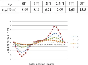
mechanical, the cogging torque was calculated. The cogging torque of a basic model with no mechanical was shown to be 8.99[N·m]. The minimum value of the cogging torque was 2.09[N·m] when the mechanical angle was 2.5 degree, which is about 77% less than that of the original shape. The simulation results for different mechanical angles are summarized in Table 2. Fig. 5 shows the cogging torque with the rotor position at different mechanical angles.
(a) αsp = 0 (b) αsp≠ 0
Fig. 4. Two types of stator core arrangements. Table 2. Cogging torque with different mechanical angle
αsp 0[°] 1[°] 2[°] 2.5[°] 3[°] 5[°]
τDD [N·m] 8.99 8.11 6.71 2.09 4.63 13.5
Fig. 5. Cogging torques with rotor position for different mechanical angles.
3.2 Different Magnet Pitch
Next, we investigated whether different magnet pitches had an influence on reducing the cogging torque of the generator. Fig. 6 shows the different magnet pitches.
(a) Same pitches (b) different pitches Fig. 6. Two types of magnet pitches.
381 The Influence of Stator Pole Shape and Its Arrangements on Cogging Torque for Double-sided AFPM Generator
The simulation results for different magnet pitches are summarized in Table 3. Fig. 7 shows the cogging torques from different combinations of magnet pitches
Table 3. Cogging torque with different magnet pitch [N·m] τδ τα 43[mm] 40[mm] 38[mm] 37[mm] 34[mm] 43[mm] 5.16 4.48 2.64 1.8 2.48 40[mm] 4.48 5.04 2.88 1.52 2.18 38[mm] 2.64 2.88 4.14 4.35 2.8 37[mm] 1.8 1.52 4.35 5.2 4.33 34[mm] 2.48 2.18 2.8 4.33 4.26
Fig. 7. Cogging torques with different combinations of magnet pitches.
4. Optimum Design of AFPM Generator Using
Response Surface Method and FEM
4.1 Optimum Design of AFPM Generator
In this step, the stator pole arrangements and magnet pole pitches were applied as the design variables to reduce the cogging torque. In order to reduce the design experiments of calculation, response surface method was used. 3D finite element method was used for calculation at each design experiment. Fig. 8 is the flow chart of the optimum design using response surface method.
Fig. 8. Flow-chart of the optimum design algorithm.
Table 4. Cogging torque for design experiments No.
Design variables Cogging torque [N·m] αsp [°] τα [mm] τδ [mm] 1 2.4 34 38.5 3.92 2 2.85 38.5 38.5 2.15 3 3.3 38.5 43 7.04 4 2.4 38.5 43 5.57 5 2.4 38.5 34 4.75 6 3.3 34 38.5 5.29 7 2.85 38.5 38.5 2.15 8 2.85 34 43 7.32 9 3.3 43 38.5 5.29 10 2.85 38.5 38.5 2.15 11 3.3 38.5 34 5.27 12 2.85 43 43 2.87 13 2.4 43 38.5 6.42 14 2.85 34 34 5.54 15 2.85 43 34 9.45
For three design variables, 15 experiments of design were btained using the Box-Benhken method as shown in Table 4.
4.2 Result and Discussion
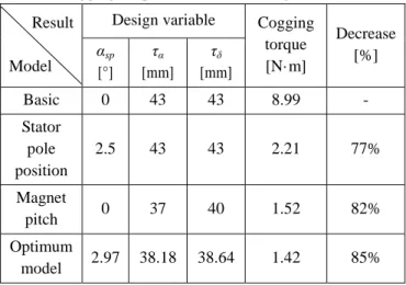
Table 5 shows a summary of the optimum values, which gives the minimum cogging torque at 1.42[N·m] when the design variables were as follows: αsp 2.79°, τα 38.18mm and
τδ 38.64mm.
Table 5. Cogging torques for different design models Result
Model
Design variable Cogging torque [N·m] Decrease [%] αsp [°] τα [mm] τδ [mm] Basic 0 43 43 8.99 - Stator pole position 2.5 43 43 2.21 77% Magnet pitch 0 37 40 1.52 82% Optimum model 2.97 38.18 38.64 1.42 85%
Chang-Eob Kim, Joong-Keun Jang, and Sung-Jun Joo 382 compared to that of the basic model. Fig. 9 shows the
cogging torques of the basic and optimum models.
(a) Basic model geometry (b) Optimum model geometry Fig. 9. AFPM machine geometry.
Fig. 10. Cogging torques of basic and optimum model.
5. Conclusion
We investigated the influence of stator pole arrangements on the cogging torque of 1kw double-sided AFPM generator. The optimum design was obtained using response surface method and 3D finite element method for three design variables – stator core position, magnet pole pitch, and the combination of the two. The cogging torque was reduced by 85% compared to that of the basic model. Future researches should be aimed to study the optimum design in consideration of the characteristics of the generator.
References
[1] J. F. Gieras, R. J. Wang, and M. J. Kamper, “Axial flux permanent magnet brushless machines,” 2nd ed., Springer, pp. 1-19, 2008.
[2] F. Profumo, Z. Zhang, and A. Tenconi, “Axial flux Machines drives: a new viable solution for electric cars,” IEEE Trans. on Industrial Electronics, vol.44, no.1, pp. 39-45, 1997. [3] Z. Zhang, F. Profumo, and A. Tenconi, “Design of an axial
flux Iinterior PM synchronous motor with a wide speed range,” Proceedings of International Conference on Electrical Machines, vol.III, pp. 273-278, 1996.
[4] M. Aydin and M. Gulec, “Reduction of cogging torque in double-rotor axial-flux permanent-magnet disk motors: a review of cost-effective magnet-skewing techniques with experimental verification,” IEEE Trans. on Industrial Electronics, vol.61, no.9, pp. 5025-5034, 2014.
[5] Gyeong-Chan Lee and Tae-Uk Jung, “Optimal cogging torque reduction design of dual stator radial flux permanent magnet generator,” 15th European Conference on Power Electronics and Applications (EPE), pp. 1-9, 2013.
[6] A. Mahmoudi, S. Kahourzade, N. A. Rahim, H. W. Ping, and M. N. Uddin, “Design and prototyping of an optimized axial-flux permanent-magnet synchronous machine,” Electric Power Applications, vol.7, no.5, pp. 338-349, 349, 2013.
Chang-Eob Kim received the B.S. and M.S degrees in electrical engineering from Seoul National University, Seoul, Korea in 1983 and 1990, and Ph.D. degree in electrical engineering from Hanyang University, Seoul, Korea in 1995. From 1983 to 1997, he worked at Hyosung Industries Co. Ltd. as a senior researcher for developing various motors, generators, circuit breakers. Since 1997, he has been a faculty member in the department of electrical engineering, Hoseo University. As a postdoctoral fellow he joined the department of electrical and electronic engineering, University of Southampton, UK, from 2000 to 2001 and as a visiting scholar he joined the department of electrical and electronic engineering, Duke University, USA, from 2009 to 2010. His main research interests are the analysis of electromagnetic fields and design of electrical machinery.
Joong-Keun Jang received B.S degree in electrical engineering from Hoseo University in 2012. He is studying for his master degree in Hoseo University. His research interests are analysis and design of electric machines.
Sung-Jun Joo received Ph.D. degree in electrical engineering from Seoul National University. He is a faculty member in the department of electronic engineering, Hoseo University. His research area is systematic design for renewable energy and energy storage system.