14-2 / K. W. Whang
IMID 2009 DIGEST •
Abstract
We suggest a new protective layer for PDP consists of SrO and MgO double layer. This double layer structure protects SrO layer from the contamination by H2O or CO2 in the air and enable SrO to play as the main cathode material. It was confirmed that the high secondary electron emission characteristics of SrO by Xe ion can bring considerable driving voltage reduction and improvement of luminance and luminous efficacy in PDP.
1. Introduction
Plasma display panel (PDP) still needs improvements in its characteristic especially in the luminous efficacy, which is directly related with the electrical power consumption as well as the circuit cost. For this reason, the efficacy improvement is one of the most important research topics now, and it is desirable to be realized with low driving voltage, because the merit of high luminous efficacy is sometimes counter balanced by the demerits of high driving voltage and thus consequent circuit loss and cost.
In this regard, many researches have been carried out to find a better cathode material because it profoundly affects the discharge voltage and luminous efficacy. Traditionally MgO has been known as the best material for PDP protecting layer so far [1] [2]. However MgO has a limitation in the secondary electron emission for Xe ion due to the high band gap energy [3], so that some new approaches have been tried to find new cathode material which has lower band gap energy and larger secondary electron emission for Xe ion [4][5]. Among them, alkaline earth metal oxides like SrO or BaO are considered as an alternative for MgO. However, SrO or BaO are very sensitive to contaminations by H2O and CO2 in
the air and needs some special provisions to keep their pristine surface properties like the vacuum sealing
process.
In this study, we suggest a SrO-MgO double layer which can be easily formed in the conventional deposition equipment but shows the desired high luminous efficacy with the low driving voltage properties of SrO.
2. Experimental
SrO is a good alternative for MgO as a high gamma cathode material, however, it is highly reactive with H2O and CO2 in the air and easily becomes Sr(OH)2 or
SrCO3, that makes it difficult to apply it to
commercialized PDP [6]. In this study, we suggest a new protective layer structure using MgO as a protection layer for SrO layer against the air, which makes it possible to preserve SrO’s characteristics in the final product.
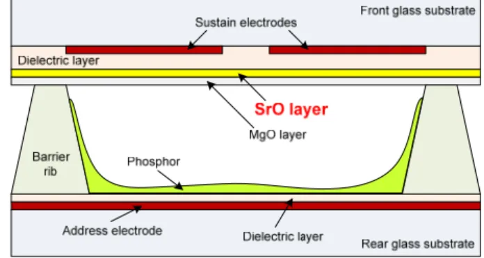
The suggested protective layer consists of SrO and MgO as shown in Fig. 1. SrO layer is deposited on the front dielectric layer and MgO layer covers SrO layer to protect it from air. MgO also can be hydrated in the air but its chemical reaction with moisture and CO2 is
not so severe and the hydrated and carbonated film thickness is limited to the shallow surface and more importantly can be calcinated at the temperature lower than the melting point of glass.
Fig. 1 Schematic of a PDP with SrO-MgO double layer
High Luminous Efficacy and Low Driving Voltage PDP
with SrO-MgO Double Protective Layer
Ki-Woong Whang, Hae-Yoon Jung, Tae-Ho Lee and Hee-Woon Cheong
Plasma Laboratory, School of Electrical & Computer Engineering, Seoul National University, San 56-1 Daehak-dong Kwanak-gu, Seoul, Korea
14-2 / K. W. Whang
• IMID 2009 DIGEST
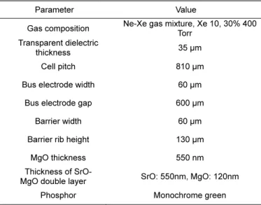
TABLE 1. Specifications of test panels used in the experiment
Parameter Value
Gas composition Ne-Xe gas mixture, Xe 10, 30% 400 Torr Transparent dielectric
thickness 35 μm
Cell pitch 810 μm
Bus electrode width 60 μm Bus electrode gap 600 μm
Barrier width 60 μm
Barrier rib height 130 μm MgO thickness 550 nm Thickness of
SrO-MgO double layer SrO: 550nm, MgO: 120nm
Phosphor Monochrome green
In order to examine the effects of SrO-MgO double layer, we made diagonal 2-inch test panels whose resolution is 50” HD (1366 × 768). Detailed panel specification is shown in TABLE 1. Each protective layer was formed on the front dielectric surface sequentially by the e-beam evaporation method without breaking the vacuum so that SrO layer is not exposed to air. Meanwhile SrO pellet calcination was carried out in a high temperature vacuum chamber at 1350℃ to get high purity SrO source. It was confirmed that the calcinated SrO source has high purity through the XRD analysis as shown in Fig. 2, the measured peaks correspond with the SrO reference ones well. Also we confirmed that SrO-MgO double layer was successfully formed on the front panel as designed through XRD analysis, SrO peaks appeared with the preferred crystal orientation of (1 1 1), (2 2 2) as shown in Fig. 3.
Other PDP fabrication processes such as panel sealing, annealing and gas injection were done under atmospheric circumstances as the usual PDP fabrication process does.
3. Results and discussion
SrO-MgO double layer structure allows the general PDP fabrication process to apply to SrO panel without any loss of the characteristics of SrO. It was successful to make test panels adopting the double layer structure and we could confirm the SrO effects with the panels in our laboratory without any additional facilities such as vacuum sealing system.
Fig. 2 XRD data of SrO pellets for e-beam evaporation
Fig. 3 XRD data of SrO-MgO double layer
In a SrO-MgO double layer panel, when discharge occurs at the beginning, it shows the discharge characteristics of conventional panels with MgO, but as aging time goes by, the MgO protective layer exposed to plasma becomes to be sputtered out and the surface is changed as shown in the Fig. 4. Especially profound erosion takes place at the inner edge surface of each display electrodes and finally the under lying SrO layer is exposed.
Fig. 4 SEM image of the SrO-MgO double layer surface after aging process
14-2 / K. W. Whang
IMID 2009 DIGEST •
Fig. 5 Sustain voltage variation of SrO-MgO double layer panel according to the aging time
Such a process can be indirectly confirmed from the monitoring of the firing and sustain minimum voltages of double layer panel as shown in Fig. 5. For the aging experiment, continuous sustain pulses of 50 kHz, 300 V were applied to the panel, the firing and sustain minimum voltages go down as the aging time progresses and at last the firing and sustain voltages are decreased by 50 V and 30 V from the values of conventional MgO panel respectively.
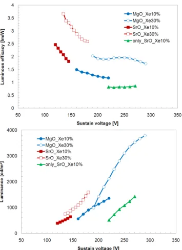
The luminance and luminous efficacy of the double layer panel are compared with those of the panels with a single MgO layer in Fig. 6. The double layer panels show lower driving voltages, higher luminance and luminous efficacy compared to MgO conventional panels. Because of the SrO effects, the double layer panel can be driven by very low voltages even if a very high Xe content gas such as Xe 30 % is used. Consequently it is possible to increase the luminous efficacy twice at low sustain voltages when the conventional simple MgO layer is replaced by the SrO-MgO double layer. On the other hand, SrO monolayer panel shows even worsen discharge characteristics; increased driving voltages and lowered luminous efficacy. Contaminated SrO layer cannot have SrO effects any more, that is why we should protect SrO layer against the air with the proposed double layer structure.
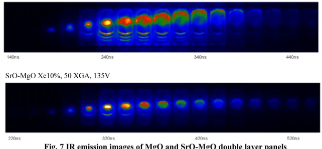
More detailed discharge characteristics of SrO-MgO double layer panels can be investigated with the IR emission image measurement. We can compare the discharge shapes and sequences of the conventional MgO and SrO-MgO double layer panels in Fig. 7, discharges are initiated from the anode near the
Fig. 6 Luminance and luminous efficacy of panels with conventional MgO layer and SrO-MgO double layer
electrode gap for the both cases, however, discharges do not move outwardly in the case of the double layer panel. As seen in Fig. 4, thin film erosion takes place mainly in the inner edges of sustain electrodes, therefore, the revealed SrO layer is localized in the cell and discharges are confined as well where secondary electrons are abundant in the double layer panel.
4. Summary
The suggested protective layer makes it possible to use SrO cathode material in PDP without the use of the vacuum sealing process, so that the luminous efficacy of the panels with a high Xe content gas can be increased significantly at the low driving voltages.
14-2 / K. W. Whang
• IMID 2009 DIGEST MgO Xe10%, 50 XGA, 185V
SrO-MgO Xe10%, 50 XGA, 135V
Fig. 7 IR emission images of MgO and SrO-MgO double layer panels
It was confirmed that the double layer structure was effective in preventing SrO contamination during the PDP fabrication process. Moreover, MgO, protection layer material, has been widely used and studied for a long time, so that the stable and predictable discharge characteristics can be acquired in the double layer panels. This approach is expected to be extended to the applications of various cathode materials to get improved discharge characteristics; high secondary electron emission coefficient, high luminous efficacy and low voltage driving.
5. References
[1] T. Urade, T. Iemori, M. Osawa, N. Nakayama, I. Morita, “A protecting layer for the dielectric in AC plasma panels”, IEEE Transactions on Electron Devices, Volume: 23, pp.313- 318, March 1976
[2] H. Uchiike, K. Miura, N. Nakayama, T. Shinoda, Y.
Fukushima, “Secondary electron emission characteristics of dielectric materials in AC-operated plasma display panels”, IEEE Transactions on Electron Devices, Volume: 3, pp. 1211- 1217, November 1976
[3] T. J. Vink, A. R. Balkenende, R. G. F. A. Verbeek, H. A. M. van Hal, and S. T. de Zwart, “Materials with a high secondary-electron yield for use in plasma displays”, Applied physics letters, Volume 80, Number 12, pp.2216-2218, March 2002
[4] Y. Motoyama, Y. Murakami, M. Seki, T. Kurauchi, and N.Kikuchi, IEEE Trans. Electron devices., vol. 54, no. 6, pp. 1308-1314, Jun. 2007
[5] T. Hirakawa, S. Goto, S. Zhang, and H. Uchiike, “Alkaline Earth Materials as Protecting Layer for AC Plasma Displays”, Eurodisplay, pp.747-750, 2002 [6] Y. Motoyama, T. Kurauchi, “Protective layer for high-efficiency PDPs driven at low voltage”, Journal of the society for Information Display, vol. 14, no. 5, pp. 487-492, 2006