ICCAS2005 June 2-5, KINTEX, Gyeonggi-Do, Korea
Intervening Firing Method and Passive Filter Design for Harmonic Elimination and Reactive Power
Compensation in Three-Phase Thyristor Phase-Controlled Converters Supplying a DC Motor
Artite Pattanapongchai*, Surached W.wongtongdee**, and Piphat Laohasongkram**
*Thai Industrial Standard Institute, Ministry of Industry, Thailand
(Tel : +66-2-2023348; E-mail: [email protected])
**Department of Instrumentation Engineering, Faculty of Engineering, Thailand
(Tel : +66-2-7392406; E-mail: [email protected],[email protected])
Abstract: This paper presents a method for harmonic elimination and reactive power compensation using an intervening firing method and
passive power filter with is suitable to compensate rapidly changing loads and reactive power. The proliferation of three-phase thyristor phase-controlled converter of DC motor drives into a power system has the potential to increase the harmonic levels in the power system. The design procedure of an intervening firing method and passive power filter capable of reducing the voltage and current harmonics produced by converter supplied from a source having internal large inductive impedance is offered. The analysis uses the orCAD PSpice to model three-phase thyristor phase-controlled converter of DC motor drives as well as the system.
Key words: intervening firing method, passive power filter, reactive power, harmonic levels
1. INTRODUCTION
The proliferation of three-phase thyristor phase-controlled converter of DC motor drives into a power system has the potential to increase the harmonic levels in the power system. Among the different three-phase loads connected to the distribution system. DC motor drives are the significant importance.
Three-phase thyristor phase-controlled converter of DC motor
drives generated the current total harmonic distortion (THDi) is
normally in the rang of 100%. Different techniques have been implemented to reduce both current and voltage harmonics. These techniques depend on using auxiliary circuits, active or passive connected in parallel at the points of common coupling and intervening firing method. The use of active electronic devices such as active filters, the electronic voltage regulator and the adaptive VAR compensator (AVC) can cause further distortion in the distribution system.
The passive circuits used to reduce the distribution system current and voltage harmonics is to use shunt capacitors, however, this may generate unexpected harmonic voltages due to the series resonance [5].
Intervening firing method [1][4] was an improved commutation arrangement for an AC to DC energy converters. The improved arrangement uses turn-off capable commutation to enable modification of the operating waveforms in the phase-controlled converters. An intervening firing method is made to the leading phase when the output is less than one-half of the maximum value. The disclosure includes mathematical consideration of source machine power factor, output waveform ripple content, and other refinements of the commutation arrangement.
This paper presents the design of passive harmonic filter[5] and the use of intervening firing technique[1][4] with is suitable to compensate rapidly changing loads and reduce the harmonic current and compensate of the reactive power in three-phase controlled converter for DC motor drives in power distribution system. This design follows harmonic standard of the Power Board (Thailand), IEC 1000-2-2 -1990 standard at the voltage 415/240 V and IEC 146 Semiconductor Converter. The experiment was done by simulating power distribution that has large DC motor as the load of the system
2. DESCRIPTION OF MODEL SYSTEM
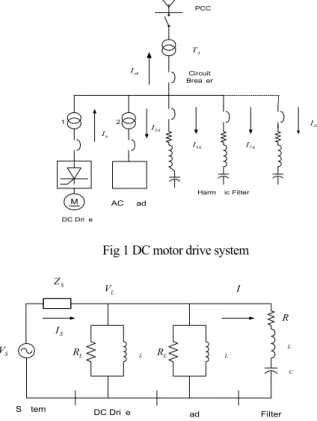
Harmonic current from three-phase thyristor phase-controlled converter of DC motor drives is a harmonic source in factory that flow into the power system and cause of the power quality problem. To solving this problem using harmonic current filters to filter harmonic current in some frequency away from the system for stopped flowing of harmonic current into the power system as shown in Fig 1 PCC Harmonic Filter Circuit Breaker Lh I Iih 5h I I7h h I DC Drive T1 T2 A T M AC Load sh I
Fig 1 DC motor drive system
S V S I L R XL F R LF X CF X S Z L V L R XL
DC Drive Load Filter
F I
System
Fig 2 Equivalent circuit of DC motor drive system
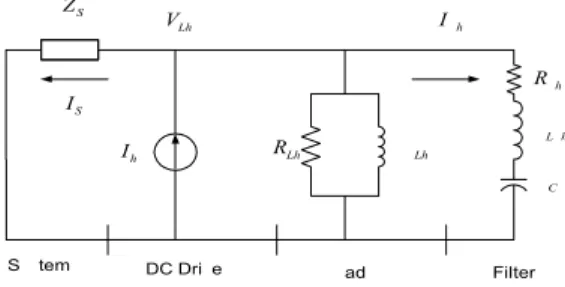
S I Lh R XLh Fh R LFh X CFh X S Z Lh V
DC Drive Load Filter
Fh I
System h I
Fig 3 Equivalent circuit of DC motor drive system at harmonic frequency
Consider this model from point of common coupling (PCC) into power system network that substitute by impedance with have resistance series with reactance. The resistance have relate with reactance in form of X R . The impedance at harmonic frequency derive form equation
2 sys S SC V Z MVA = (1) sh s s Z =R + jhX (2)
where ZS is the power system impedance(Ω )
SC
MVA is the short circuit power( MVA
)
sh
Z is the impedance at harmonic frequency(Ω )
s
R isthe resistance of the power system(Ω )
s
X isthe reactance of the power system(Ω )
An harmonic analyzing will model transformer with impedance that consist of resistance series with leakage reactance that vary with harmonic order number, and the resistance value is constant when don’t add result form skin effect, so at the harmonic frequency, the transformer impedance have a value
2 % 100 1000 Tr Z V Z KVA = × × (3) 2 2 ( 1000) Tr c V R P KVA = × × (4) Trh Tr Tr Z =R + jhX (5)
where Z is the impedance of the transformer( Ω ) Tr
%Z
is
the impedance at harmonic frequency of thetransformer (Ω )
V
is
rated voltage of the transformer(V)
Tr
R
is
the resistance of the transformer(Ω )c
P
is
the winding loss( kW)
The linear model system consist of resistance and reactance that find form real power (P) and reactive power (Q) of load
2 1 sys L V R P = (6) 2 1 . sys L V X h Q = (7)
where RL is load resistance at harmonic frequency(Ω )
1
P is real power of load
(
W)
1
Q is reactive power of load(VAR )
L
X
is
load reactance at harmonic frequency(Ω )2.1 Reactive power compensation
The tuning proportions reactive power of harmonic current filter must concern with flowing of harmonic current in the power system that limited international harmonic standard
, 1 h com h com n h i I Q Q I = = ×
∑
(8)where Qcom is compensate reactive power(VAR )
h
I is harmonic current order h ( A )
2.2 Harmonic passive filters
The working of harmonic passive filter comprise of 3 components, Capacitor, Inductor and the resistance in form of inductance. These components connected in series resonant for making harmonic passive filter having lower impedance at resonant frequency that called series resonant. At tuning frequency , harmonic passive filter have a impedance equal with a resistance because of at resonant frequency the value of capacitive reactance have a value equal inductive reactance but pole inverse, so the value of reactance can to wipe out. The calculation value of the capacitance(C) inductance (L) and resistance(R) using equation Table 1 Tuning point for this experiment
Range of Tuning
Point Lower Limit Upper Limit
Order 5th 4.5 4.9 Order 7th 6.5 6.9 1 2 . C C f X π = (9) 2 2 . C h X L f n π = (10) 2 h L atn F X R Q = (11)
2.3 Intervening firing method
Fig 4 Intervening firing method at α=80 ,ο β=20ο
Output voltage Vd, Vripple and input reactive power( Qi) find from equation
1 ( ) 2 sin( ) d d n n n v t v ∞ V n tω ψ = = +
∑
+ (12) 2 1 ripple n n V ∞V = =∑
(13) 1 1 3 an cos P= V I φ (15) 1 3 an1sin 1 Q = V I φ (16)2.4 Harmonic standard of the Power Board of Thailand
For apply with nonlinear load that using in Thailand factory for
1 phase and 3 phase refer with standard of G.5/3-1976:
Engineering Recommendation but proving level of voltage that suitable for supplying voltage level in Thailand
3. Experimental
The experiment starting with model the power system 12 kV, 50 Hz, 2000 MVA, X/R ratio =10 as shown in Fig 1 supplying 6 pulse phase-controlled converter that using for DC motor drive rated 2 HP, 130 V, 1800 rpm, series DC motor. The converter is operated from a 3 phase transformer 2000 kVA, 12kV/100 V, 50 Hz, Loss 30 kW, %Z=6 The rated armature current of the motor is
15 A. The motor parameters areRa=1.429Ω, La=15.01mH. The
experiment test at 50 % rated load and tune firing at 80 degree,
intervening firing at
β
=30. Measuring harmonic current thatflowing in the power system and compare with international harmonic standard.
Table 2 Harmonic current measured form ac-side of 6 phase controlled converters at 50% rated load
Harmonic
Order Magnitude(%I1) Harmonic Order Magnitude(%I1)
5 7 11 13 17 26.21 18.31 12.01 9.78 7.84 19 23 25 29 31 6.64 5.85 5.01 4.69 4.01
4. Result
Table 3 Harmonic current analysis from converter flow into the system transformer and power system
Low Voltage Side High Voltage Side Order Harmonic Source (A) Transformer (A) System (A) Power Board Limit (A) 5 7 11 13 17 19 23 25 29 31 30.87 21.71 11.90 8.60 5.31 4.10 3.03 2.43 2.12 1.82 26.67 18.65 9.60 7.55 4.63 3.57 2.60 2.07 1.82 1.54 4.49 3.10 1.70 1.23 0.87 0.58 0.47 0.35 0.25 0.23 10 8 7 6 2 1 - - - - Total 204.20 175.12 5.58 -
Table 4 Harmonic voltage measured from low voltage side of system transformer
Low voltage side
h voltage
%
h voltage%
1 5 7 11 13 17 380 14.43 14.12 11.53 10.61 8.48 100 3.80 3.71 3.03 2.79 2.23 19 23 25 29 31 7.28 6.48 5.62 5.65 5.15 1.92 1.71 1.48 1.49 1.36 Table 5 Harmonic voltage measured from high voltage side of system transformerHigh voltage side
h voltage
%
h voltage%
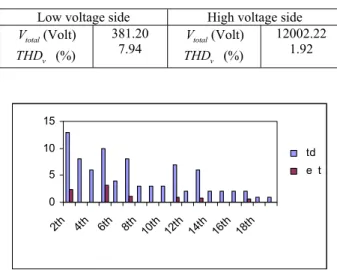
1 5 7 11 13 17 12000 110.36 108.02 88.21 81.21 64.88 100 0.92 0.90 0.74 0.68 0.54 19 23 25 29 31 55.76 49.64 42.98 43.23 39.41 0.46 0.41 0.36 0.36 0.33 Table 6 Harmonic voltage of the systemLow voltage side High voltage side
total V (Volt) v THD (%) 381.20 7.94 Vtotal(Volt) v THD (%) 12002.22 1.92 0 5 10 15 2th 4th 6th 8th 10th 12th 14th 16th 18th Harmonic Order % I h std Test
Fig 5 Comparison between harmonic current standard of the Power Board (Thailand) and the experiment
0 1 2 3 4 2th 4th 6th 8th 10th 12th 14th 16th 18th Harmonic Order %V h std Test
Fig 6 Comparison between harmonic voltage standard of the Power Board (Thailand) and the experiment
0 2 4 6 8 5th 7th 11th 13th 17th 19th 23th 25th Harmonic Order %V h IEC 1000-2-2 Test
Fig 7 Comparison between harmonic voltage standard of the IEC
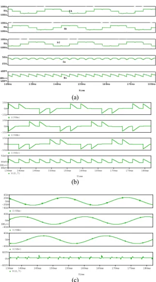
1000-2-2 -1990 standard (a) Time 140ms 145ms 150ms 155ms 160ms 165ms 170ms 175ms 180ms 136ms V(0,7) 88mV 90mV 92mV SEL>> I(VSc) -10A 0A 10A I(VSb) -10A 0A 10A I(VSa) -10A 0A 10A (b) Time 140ms 145ms 150ms 155ms 160ms 165ms 170ms 175ms 180ms 136ms V(0,7) -400V 0V 400V I(VSc) -40A 0A 40A I(VSb) -40A 0A 40A SEL>> I(VSa) -40A -20A 0A 20A 40A (c)
Fig 8 Comparison between firing
α =
80
(a), interveningat α=80,β =30(b), and with passive filter(c)
5. Conclusions
Harmonic elimination of DC output voltage and reactive power compensation of input current that generated form 6
pulse phase-controlled converter by using intervening firing method every 1/6 period and using harmonic passive filter can reduce harmonic generation of DC output voltage and reactive power generation of input current. And when compare with the Power Board of Thailand standard and IEC 1000-2-2 -1990 standard, the result is a good tend and can improve the input power factor of the system.
References
[1] D.L. Lafuze, “Turn-off switch phase control with improved ripple and power factor” U.S. Patent No.5, 198, 972, 1993.
[2] N.Mohan, T.M. Undeland, and W. P. Robbins, Poer
Electronics : Converter, Application, and Design-2nd
Edition, John Wiley & Sons, Inc., 1995, pp. 138-153 [3] J. Lazar “Park-vector Theory of Line-commutated
Three-Phase Bridge Converters” Serial editior Volume 1,Omikk Publisher Budapest,1987, pp. 14-66
[4] I. G. Park and J. T. Yoon, “Charecterizing the double Firing Method For three-phase thyristor phase controlled converter,” in Proc. IECON 96 , 1996, pp. 689-694
[5] Artite Pattanapongchai and Piphat Laohasongkram “Harmonic passive filter study and design by using three-phase thyristor phase-controlled converter”
Engineering journal, Khonekean University issue 1(61-77) January-March 2003 page 61-77
Appendix
Snubber Circuits for 6 pulse phase controlled converter
The reverse-recovery currents generated in thyristors when they are reverse biased may result in unacceptably large overvoltages because of series inductance
0.6
d s LLI
C
V
=
20
LL s dV
R
I
=
where
I
dis output dc current
LLV
is voltage input line-linetotal energy loss in each snubber
2
3
snubber s LL