INTRODUCTION
Composites give a chance to create new effects by com-bining the properties of known materials in an intelligent way. The variation of the relation between the resistivity of carbon black (CB)/polymer composites and temperature is a typical example (Strumper et al. 1997). These materials display either a positive temperature coefficient (PTC) effect or a negative temperature coefficient (NTC) effect (Jia and Chen 1997). Below a specific critical temperature, the poly-mer is in a low-resistance state. Above the critical tempera-ture, the polymer goes over to a high- resistance state (Chan and Cheng 1997), the resistivity of the PTC composite increases abruptly by many orders of magnitude (Mather and Thomas 1997; Yi et al. 1997). Because of the large resistance anomaly, these materials are useful in devices
that limit electric fault currents. There is a positive feed-back mechanism involved in the increase of temperature and resistance, the composites can switch quickly from a low- to high -resistance state (Sichel 1981).
The electrical conductivity of CB is influenced by its particle size, aggregate shape and structure, porosity, and its surface chemistry. Blended in a polymer, the electrical conductivity of CB/polymer mixtures then depends also on polymer characteristics such as chemical structure and processing conditions. PTC effect of CB/Polymer compo-site can be at least partly explained by the rapid expansion of the system undergoing melting, thereby increasing the gaps between CB and thus hindering the electrical con-ductivity (Kohler 1966; Wartgotz and Alvino 1967; Ohe and Naito 1971). The lack of electrical reproducibility and the NTC effect are two main drawbacks to the application of PTC materials. Therefore, efforts to improve the perfor-mances of PTC materials have been made in depth (Meyer 1973, 1974). The NTC effect is presumably caused by the
─ ─ 47 ──
Effect of Carbon Black on PTC of PEO/CB Composites
Phil Hyun Kang*, Joon Pyo Jeun and Young Chang Nho
Advanced Radiation Technology Institute, Korea Atomic Energy Research Institute, Jeongeup 580-185, Korea
Abstract -- The relation between the resistivity of carbon black (CB)/polyethylene oxide (PEO) composites and temperature can vary greatly. These materials can display either a positive temperature coefficient (PTC) effect or negative temperature coefficient (NTC) effect. The study reported herein focused on composites of CB in PEO that have low room temperature resistivity and a large PTC at switching temperature. CB/PEO composites were made with five different types of CB, and the carbon content was systematically varied. The CB and PEO were mixed in a Brabender Plastograph. The CB/PEO blend thus produced was sandwiched between a pair of copper foils (0.04 mm thick), which served as electric contacts. The thickness of the sample was approximately 0.5 mm. The CB/PEO sheet was irradiated with γγ-rays for the purpose of reducing the NTC of the conductive composite. The electrical conductivity of CB mixtures was found to depend on the crosslinking degree, the molecular weight of PEO, the particle size and structure of CB.
Key words : Composites, PEO, Carbon black, Radiation
* Corresponding author: Phil Hyun Kang, Tel. +82-63-570-3061, Fax. +82-63-570-3068, E-mail. [email protected]
movement of the polymer in the molten state and the for-mation of a new distribution of CB in polymers. Crosslin-king has been considered to be an effective way to dra-matically reduce the freedom of movement of the CB at high temperatures and thus eliminate the NTC effect. Already there exist a number of papers reporting either irradiation crosslinking at room temperature or peroxide chemical crosslinking in the molding operation to reduce NTC effect (Tang et al. 1993, 1997). Narkis reported that the PTC intensity is affected not only by the species of polymer and CB, but also by the processing conditions (Narkis et al. 1980).
It should be noted, however, that most of the earlier stud-ies focused on the composites comprising CB and polyeth-ylene polymer. Few studies have been conducted on the PTC and NTC effects of CB filled polyethylene oxide (PEO) with low melting temperatures below 70�C. The study reported herein focused on composites of CB in PEO that have low room temperature resistivity and a large PTC at a relatively low switching temperature. Composites with CB/PEO were made from several different types of CB, and the carbon content was systematically varied. Irradia-tion of PEO/CB was tried for the purpose of reducing the NTC of the conductive composite.
MATERIALS AND METHODS
1. MaterialsA commercial grade PEO was used throughout this study
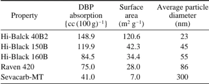
and was supplied by Aldrich Chemical Company, USA. The molecular weight of PEO selected was between 2,000,000 and 8,000,000. Five different CB was used in this study and their characteristics are listed in Table 1. CB with particle sizes ranging from 23nm to 300nm was used. The Hi-Black CB was supplied by Korea Carbon Black Co., Ltd. The Raven 420 CB and Sevacarb-MT CB were supplied by the Columbia Chemicals Company, USA. The structure of CB is generally characterized by DBP (dibutyl phthalate) absorption and BET nitrogen adsorption. Highly structured CB contains more void spaces.
2. Sample preparation
CB and PEO were mixed in a Brabender Plastograph at 120�C for 15 min. Range of concentration (wt%) of CB in PEO was 30~50 wt%. The composition thus produced was sandwiched between a pair of copper foils (0.04 mm thick), which served as electric contacts (Fig. 1). The thickness of the sample was approximately 0.5 mm. The PTC samples were irradiated by γ-rays to total doses of 50, 100 and 150
Table 1.Characteristics of Carbon Blacks
DBP Surface Average particle Property absorption area diameter
{cc (100 g)-1} (m2g-1) (nm) Hi-Balck 40B2 148.9 120.6 23 Hi-Black 150B 119.9 42.3 45 Hi-Black 160B 84.5 34.4 55 Raven 420 75.0 28.0 86 Sevacarb-MT 41.0 7.0 300 PEO/CB
Conductive PEO/CB sheet
Electrode Pressing PEO/CB Gamma-ray Radiation crosslinking Punching PEO/CB Mixing
kGy at a dose rate of 10 kGy hr-1at room temperature in nitrogen. The degree for crosslinking is evaluated in a gel test.
3. Measurements of sample
As shown in Fig. 2, electrical resistivity was measured with a digital multimeter (Keithley Instruments model 2000). The PTC samples were placed in an oven to measure the electrical conductivity at various temperatures and 4 wires were used for the connection between the sample and the multimeter. A computer system equipped with a GPIB card was used for automatic data acquisition. The crystal melting temperature of PEO was measured using differen-tial scanning calorimetry (DSC) (DSC-7 Series Thermal Analysis System, Perkin Elmer). Heating runs were con-ducted from 30�C to 100�C at a rate of 10�C min-1in nitro-gen. The heat of fusion was obtained by integrating the area under the endothermic peak. The degree of crosslinking in the irradiated PTC sample was determined by measuring the insoluble content using the extraction method. The samples were extracted with boiling solvent for 24 hr and dried under a vacuum at 50�C to a constant weight.
RESULTS AND DISCUSSION
1. Influence of structure of CB on resistivity ofCB/PEO
As shown in Table 1, Hi-Black 40B2 CB exhibited the
highest DBP absorption and surface area among all CB used in this study. This means that Hi-Black 40B2 CB has the smallest particle size (its average particle diameter was 23 nm) and thus a highly aggregated structure. Sevacarb-MT CB has the lowest DBP absorption and surface area among the five CB used in this study. It has the largest particle size (300 nm) and lowest aggregated structure. Fig. 3 shows change of resistivity at room temperature of PEO filled with different contents of CB. The resistivity of the CB-filled PEO decreased with an increase in content of the CB. It was shown that the resistivity at room temperature increased in the order of Sevacarb-MT, Raven 420, Black 160B, Black 150B, and black-40B2. For
Hi
-PTC sample
Resistivity
Multimeter Data acquisition system T.C.
Fig. 2. Schematic diagram of electrical resistivity of CB/PEO
composite. Content of carbon black (wt%)
25 30 35 40 45 50 55 Resi sti v it y at r oom tem per atur e( ohm. cm ) 1×10¹⁰ 1×10⁹ 1×10⁸ 1×10⁷ 1×10⁶ 1×10⁵ 1×10⁴ 1×10³ 1×10² 1×101 1×100 1×10⁻¹ Hiblack40B2 Hiblack150B Hiblack160B Raven420 sevacarb-MT
Fig. 3. Resistivity at room temperature of CB filled PEO versus
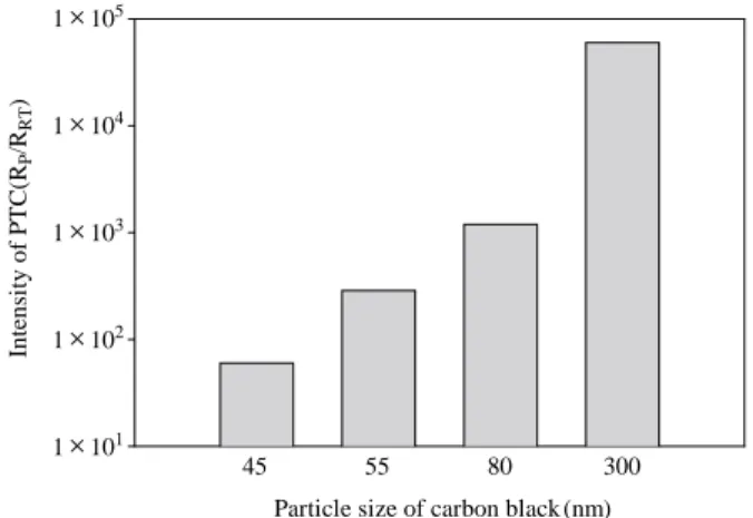
content of CB Intens it y of P TC (R P /R RT ) 45 55 80 300 Particle size of carbon black (nm) 1×10⁵
1×10⁴
1×10³
1×10²
1×101
Fig. 4. Resistivity at room temperature of CB filled PEO versus
black40B2 loaded PEO, the resistivity at room temperature of the composite is close to 2.4 Ωcm for the loading amount of 30wt%. However, it was difficult to mix more than 30wt% Hi-black40B2 with PEO because of its highly aggregated structure. The Sevacarb-MT CB filled PEO showed the highest resistivity at the same CB loading. Fig. 4 shows the PTC intensity of CB filled PEO relative to different particle size of CB. The PTC intensity increased with an increase in the CB particle size. For Sevacarb-MT CB, which had the largest size in this study, the PTC intensity was above 104. Since Sevacarb-MT CB has the largest particle size and lowest surface area, it is difficult to form a conductive pathway in its polymer matrix. There-fore, Sevacarb-MT CB- filled PEO demonstrated the larg-est resistivity at the same CB loading. It was found that the
PTC intensity increased with the increase in particle size of CB.
2. PTC behavior of CB filled PEO
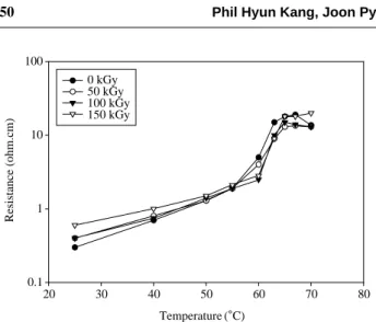
Figs. 5~8 show the effect of radiation dose on the resisti-vity of the conductive composite loaded with different CB as a function of temperature when CB/PEO composites were irradiated with 0, 50, 100, and 150 kGy, respectively. The resistivity increased slightly as the temperature was raised from 20�C to 60�C, and increased more rapidly above 60�C as the polymer crystal started to melt. The resistivity reached a peak value at around 67�C. For a non-irradiated sample, the resistivity decreased with a further increase in temperature. This NTC phenomenon can be accounted for by the formation of conductive chains resul-Temperature (�C) 20 30 40 50 60 70 80 Resistance (ohm.cm) 0.1 1 10 100 0 kGy 50 kGy 100 kGy 150 kGy
Fig. 5. Effect of radiaton dose on the resistivity of the
Hi-Bl-ack150B/PEO composite. Temperature (�C) 20 30 40 50 60 70 80 Resi st iv it y (ohm .c m ) 0.1 1 10 100 1000 10000 0 kGy 50 kGy 100 kGy 150 kGy
Fig. 6. Effect of radiaton dose on the resistivity of the
Hi-Bl-ack160B/PEO composite. Temperature (�C) 20 30 40 50 60 70 80 R es is tivity (ohm.c m) 0 kGy 50 kGy 100 kGy 150 kGy 1×10⁵ 1×10⁴ 1×10³ 1×10² 1×101 1×100
Fig. 7. Effect of radiaton dose on the resistivity of the Raven 420
/PEO composite. Temperature (�C) 20 30 40 50 60 70 80 Resi st iv it y (ohm .c m ) 0 kGy 50 kGy 100 kGy 150 kGy 1×10⁸ 1×10⁷ 1×10⁶ 1×10⁵ 1×10⁴ 1×10³ 1×10² 1×101
Fig. 8. Effect of radiaton dose on the resistivity of the
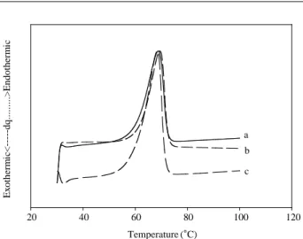
ting from the relaxation of the polymer structure and agglo-meration of CB particles. This temperature coincided with the endothermal peak temperature of the DSC curve (Fig. 9). It can also be seen from Figs. 5~8 that the PTC ampli-tude increased in the order of Sevacarb-MT, Raven 420, Hi-Black 160B, and Hi-Black 150B systems. As shown in Fig. 8, Sevacarb-MT CB with the largest particle size has the least aggregated structure and surface area, the resis-tivity of the composite filled with Sevacarb-MT is higher than those of the composites loaded with other CB at the same loading. The irradiated conductive composite had a higher peak resistivity compared with the non irradiated composite. When the composites were irradiated with γ-ray to a total dose above 150 kGy, the NTC behavior disappear-ed, indicating that the crosslinked network remained
effective above these dose levels, thereby preventing CB migration and stabilizing the PTC behavior of the compo-sites. It is thus shown that with certain conductive CB, it is possible to practically eliminate the NTC effect by proper crosslinking without sacrificing much of the PTC intensity. The degree of crosslinking in the range studied (0~80% gel) has no distinct effect on the peak temperatures and on the melting curve (50~70�C). The gel content in the irra-diated PTC sample was determined by measuring the in-soluble content using the extraction method. Gel in the polymer increased with the irradiation dose up to 150 kGy Temperature (�C) 20 40 60 80 100 120 E xotherm ic < ---dq...> E ndotherm ic a b c
Fig. 9. DSC thermogram of PEO (MW of PEO: a: 2,000,000; b:
4,000,000; c: 8,000,000).
Absorbed dose (kGy)
0 20 40 60 80 100 120 140 160 Degr ee of gel (% ) 0 20 40 60 80 100 MW of PEO: 2,000,000 MW of PEO: 4,000,000 MW of PEO: 8,000,000
Fig. 10. Degree of gel of CB/PEO composite with irradiation.
Content of carbon black (wt%)
38 40 42 44 46 48 50 52 Resi sti v it y at r oom tem per atur e( ohm .cm ) 0 20 40 60 80 100 120 140 non-irradiated-2,000,000 (M.W. of PEO) non-irradiated-4,000,000 (M.W. of PEO) non-irradiated-8,000,000 (M.W. of PEO) irradiated(150 kGy)-2,000,000 (M.W. of PEO) irradiated(150 kGy)-4,000,000 (M.W. of PEO) irradiated(150 kGy)-8,000,000 (M.W. of PEO)
Fig. 11. Resistivity at room temperature of CB (Raven 420) filled
PEO.
Content of carbon black(wt%)
38 40 42 44 46 48 50 52 Peak resi st iv it y( ohm .c m ) non-irradiated-2,000,000 (M.W. of PEO) non-irradiated-4,000,000 (M.W. of PEO) non-irradiated-8,000,000 (M.W. of PEO) irradiated (150 kGy)-2,000,000 (M.W. of PEO) irradiated (150 kGy)-4,000,000 (M.W. of PEO) irradiated (150 kGy)-8,000,000 (M.W. of PEO)
1×10⁷ 1×10⁶ 1×10⁵ 1×10⁴ 1×10³ 1×10²
(Fig. 10). Radiation crosslinking in the composite signifi-cantly improved the reproducibility and eliminated the NTC behavior of the CB filled PEO above its melting point. Figs. 11~12 show the effect of irradiation and mole-cular weight of PEO on the resistivity at room temperature and peak resistivity of CB (Raven 420) filled PEO. The peak resistivity of the composite increased as the molecular weight of PEO increased, while the resistivity at room temperature of the composite decreased as the molecular weight of PEO increased.
CONCLUSION
The study reported herein focused on composites of CB in PEO that have low room temperature resistivity and large PTC at switching temperature. The resistivity ratio of the CB-filled PEO increased with an increase in the surface area of CB. It was shown that the resistivity ratio increased in the order of Sevacarb-MT, Raven 420, Hi-Black 160B, Hi-Black 150B and Hi-Black40B2 systems. With certain conductive CB, it is possible to practically eliminate the NTC effect by proper crosslinking without sacrificing much of the PTC intensity. Gel content in the range studied has not much effect on the peak temperatures and on the melt-ing curve. The PTC intensity of the composite increased as the molecular weight of PEO increased, while the electrical resistivity of the composite decreased as the molecular weight of PEO.
ACKNOWLEDGEMENT
The present work was supported by the Nuclear R&D program from the Ministry of Science &Technology, Korea.
REFERENCES
Chan CM and Cheng CL. 1997. Electrical properties of
poly-mer composites prepared by sintering a mixture of carbon black and ultrahigh molecular weight polyethylene pow-der, Polym. Engineer. Sci. 37:1127-1136.
Jia W and Chen X. 1997. Effect of polymer-filler interactions on PTC behaviors of LDPE/EPDM blends filled with carbon black. J. Appl. Polym. Sci. 66:1885-1890.
Kohler F. 1966. U.S. Pat. 3,243,753.
Meyer J. 1973. Glass transition temperature as a guide to selection of polymers suitable for PTC materials. Polymer Eng Sci. 13:462-468.
Meyer J. 1974. Stability of polymer composites as positive-temperature-coefficient resistors. Polymer Eng and Sci.
14:706-716.
Mather PJ and Thomas KM. 1997. Carbon black/high density polyethylene conducting composite materials. J. Mater. Sci. 32:1711-1715.
Narkis M, Ram A and Stein Z. 1980. Effect of crosslinking on carbon black/polyethylene switching materials. J. Appl Polym Sci. 25:1515-1518.
Ohe K and Naito Y. 1971. New resistor having an anomalou-sly large positive temperature coefficient. Japan J Appl Phys. 10:99-108.
Sichel EK. 1982. Carbon black polymer composites. Marcel Dekker, New York.
Strumper R, Maidorn G and Rhyner J. 1997. Fast current limi-tation by conducting polymer composites. J. Appl. Phys.
81:6786-6794.
Tang, H, Piao J, Chen X, Luo Y and Li S. 1993. The positive temperature coefficient phenomenon of vinyl polymer/CB composites. J. Appl Polym Sci. 48:1795-1800.
Tang H, Piao J, Chen X, Luo Y and Li S. 1997. Studies on the PTC/NTC effect of carbon black filled low density poly-ethylene composites. Eur. Polym. J. 8:1383-1386.
Wartgotz B and Alvino WM. 1967. Conductive polyethylene resins from ethylene copolymers and conductive carbon black. Polymer Eng. Sci. 9:63-70.
Yi XS, Wu G and Pan Y. 1997. Properties and applications of filled conductive polymer composites. Polym. Interna-tional. 44:117-124.
Manuscript Received: May 18, 2007 Revision Accepted: June 12, 2007