A thesis submitted to the School of Electrical and Computer Engineering and the Graduate School of UNIST. 77-GHz waveform generator with multiple frequency shift keys for multi-target detection automotive radar applications. In automotive radar applications, the modulation waveform plays an important role in detecting multiple targets.
In addition, the proposed MFSK waveform generator for automotive radar systems is developed to improve the target detections and shorter measurement time.
Motivation
There would be multiple targets, pedestrians and vehicles in the observation area, and all targets must be detected by the radar sensor, including fixed targets. This results in a significant reduction in product costs and an increase in measurement accuracy.

Modulation Waveform for Multi-target Detection
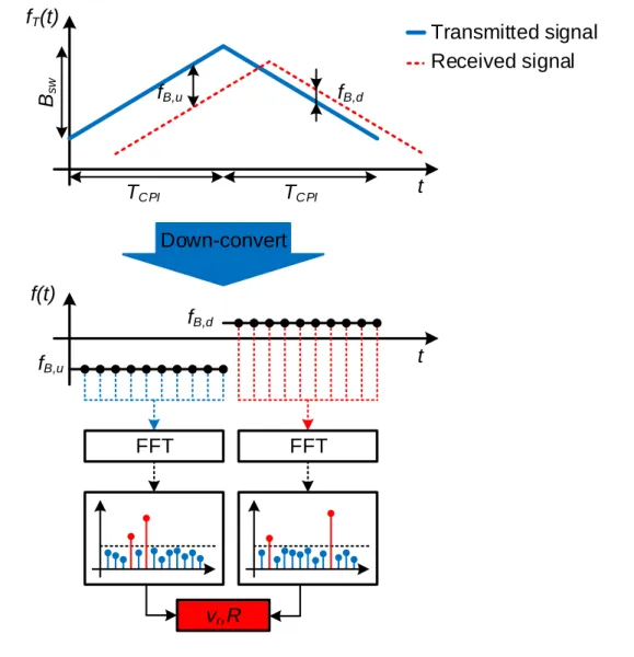
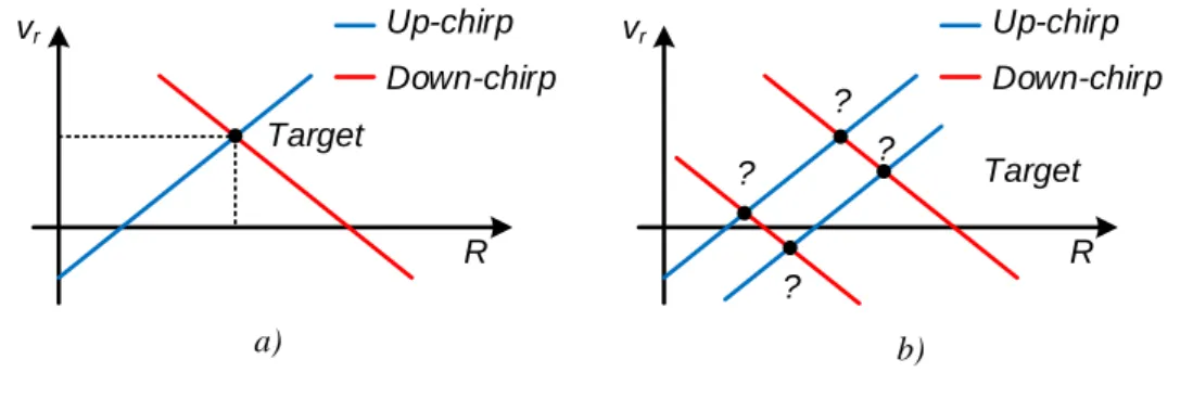
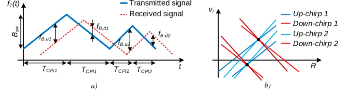
The point of intersection of these two equations can be plotted on the range-velocity plane, as shown in Figure 1.5-a. In other words, FMCW radars cannot fully succeed in clearly measuring target range and radial velocity in multi-target scenarios. The target range information R can be estimated from the phase difference of the two interpolated frequencies.
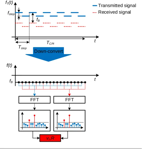
In multi-target situations, if the targets have different velocities, these targets can be detected by their Doppler frequencies. The MFSK waveform can improve the detection capability of a radar system, even in multi-target scenarios. In addition, the target area and the relative speed of cars or pedestrians can be estimated simultaneously even in multi-target cases, where all ambiguous targets can be completely removed.
Currently, the FMCW waveform is widely used in the market, but the limitations of this modulation in multi-target scenarios cannot be completely avoided. A Phase-Locked Loop (PLL) incorporates the VCO, compensates the non-linearity of the VCO by feedback technique so that the output frequency can be stabilized. The modulation signal can be realized by generating the digital code using a Direct Digital Frequency Synthesizer (DDFS).
Diophantine Phase Locked Loops
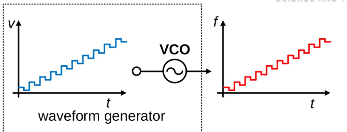
There are tremendous improvements in radar applications, several methods have been proposed to generate the modulation signal. A basic idea is to apply an appropriate control voltage to the input of a voltage-controlled oscillator (VCO), as shown in Figure 2.1. In case of linear voltage-frequency characteristic of the VCO, the output frequency will be modulated according to the input voltage.
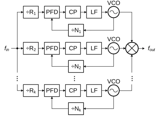
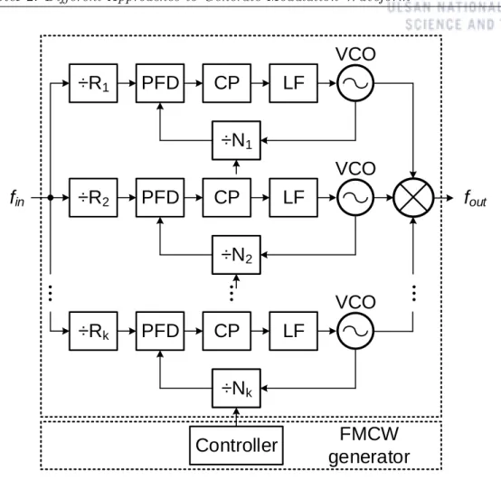
The Diophantine Frequency Synthesis (DFS) is one of the solutions that can provide a fine frequency step while guaranteeing fast frequency jumps. The output frequency of DFS is the product of mixing output frequencies of PLLs, adding or subtracting two or more frequencies. In the case of a single PLL, the frequency step is equal to the reference input of the phase frequency detector (PFD), fin/Ri.
A small frequency step can be achieved by using a large division value of Ri and/or small reference input fin. The trade-off between the frequency step and high bandwidth can be eased with a DFS [12,13]. DFS allows the frequency shift to be made arbitrarily small with a reasonable divider and small reference frequency.
VCO …
Direct Digital Frequency Synthesizer
DDFS has the ability to generate various modulation waveforms by programming the control code in digital form via a high-speed serial peripheral interface (SPI). The output frequency is determined by two inputs, the system clock fclk and the setup word M. Since DDFS is compatible and can be incorporated into CMOS technology, using a DDFS that generates a modulated reference signal for the PLL is a suitable approach.
The PFD detects the phase and/or frequency difference between the reference signal and the feedback signal.
VCO PFD
FMCW generator
XO SSB
Fractional-N Phase Locked Loops
FMCL
Proposed MFSK Waveform Generator
The proposed waveform generator is based on a fractional-N PLL incorporating an MFSK Modulation Control Logic (MMCL). The PLL consists of a Phase Frequency Detector (PFD), Charge Pump (CP), Loop Filter (LF) and the Multi-Modulus Frequency Divider (MMFD) controlled by the ∆−Σ Modulator (DSM). Then its output is multiplied by 6, making the operating frequency range of the proposed generator 76-77 GHz.
In this design, the loop bandwidth is chosen to be about 500 kHz and the phase difference is about 550. These chosen parameters ensure that the PLL will not fall into the oscillation region, it will be stable with a moderate lock time . This reference source will be compared to the divided signal coming back from the output.
MMCL
MFSK generator
12.65-12.85 GHz
The sink or source current is controlled by the two input pairs: UP/UPB and DN/DNB. In case UP and DN are equal, a small leakage current will flow through or from the loop filter. For that reason, this RC section is able to minimize the ripple of the control voltage to the VCO and reduce the spurs caused by.
The voltage generated from the loop filter will lead to the input of the voltage controlled oscillator (VCO). A divider is integrated into the device, so the output can be divided before being fed to the frequency divider. The function of this stage is to divide the output frequency of the VCO by 4.
The multimodule frequency divider (MMFD) is the main component that controls the fractional division ratio. The D flip-flop adopts the TSPC topology, in which AND gates are embedded in latches (see Fig.
CLK A
MFSK Modulation Control Logic
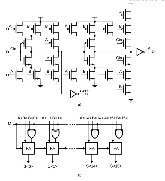
The main components of the MMCL are an accumulator based on an adder/subtractor, accompanied by an adder and a comparator. For the adder, the Ripple-Carry Adder (RCA) architecture is used due to the low operating frequency, and the output contains 16 bits. To switch the role of the accumulator between the adder and subtractor functions, an XOR gate is added in front of each input.
The selection of the adder or subtracter function will be performed simultaneously with the two inputs INC and STEP. In other words, the control code will increase linearly by the value of INC, but the output will decrease by the amount of STEP per time step. The accumulator content is reduced by the amount of STEP and FSK modulation is achieved.
In the next cycle, the output is increased by a step of INC due to the low level of SEL. At the end of the chirp, the RESET signal is generated at the last FSK step. The reset circuit will clear the contents of the accumulator, reset the output to the minimum value and start a new chirp.
MFSK Transceiver Implementation
Chirp generation is started when START goes high and modulation begins with the minimum value MIN. In the receiver chain, the input signal is first amplified by a Low Noise Amplifier (LNA), which has a signal gain of 15 dB and a Noise Figure (NF) of 4.5 dB. The local oscillator (LO) signal for the mixer is taken from the transmitted signal using a current divider.
The receiver design from MMIC is based on the front-end module in [16]. Note that this radar sensor does not include the signal processing part and antennas.
MFSK Waveform Generator
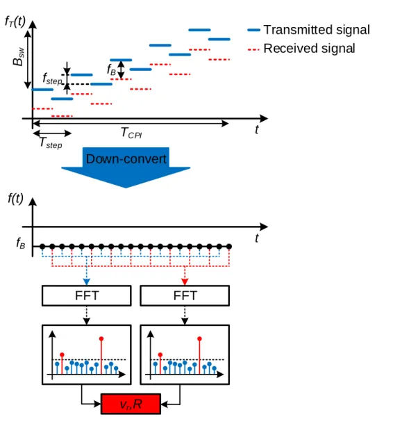
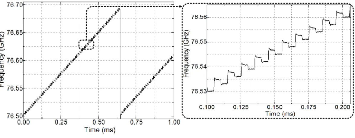
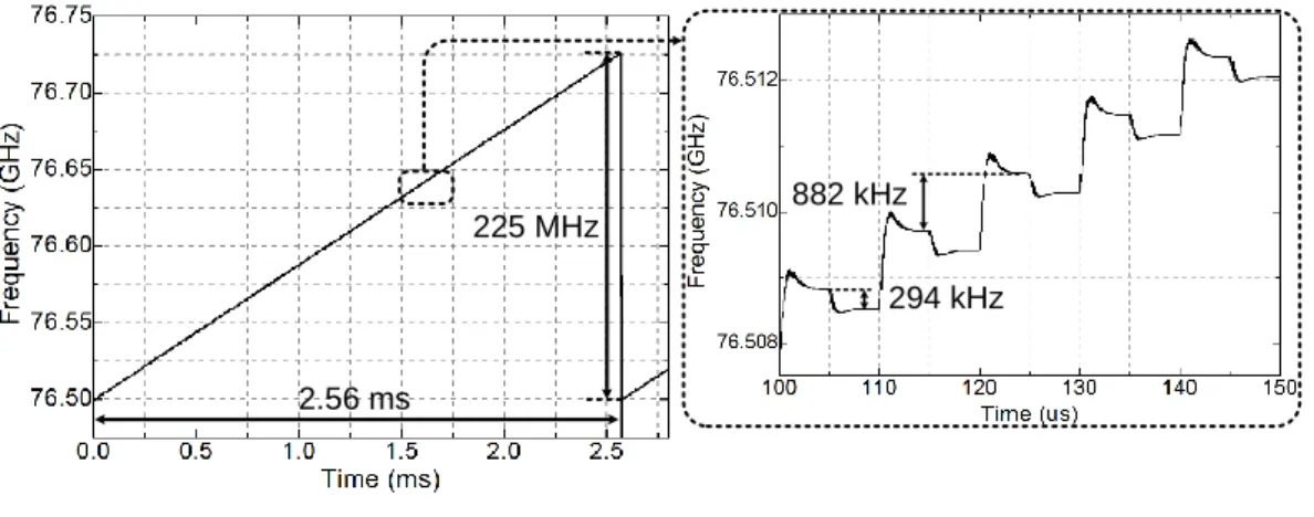
A large bandwidth leads to a higher speed resolution, and a shorter modulation time can reduce the speed error caused by the variation of the target speed. Figure 4.3 thus shows the modulation with a bandwidth of 300 MHz and the coherent processing interval of 2.56 ms. By setting the same parameters as in the first case, but changing the number of steps to 128, the bandwidth is reduced to 75 MHz.
However, the velocity resolution is dependent on the chirp time, the short sweep results in the large velocity resolution. The INC parameter of the MMCL has the ability to control the frequency gain in the MFSK waveform. The frequency increase is three times the frequency step, which means finc=882 kHz, as shown in Figure 4.5.
A larger frequency step may cause a measurement error due to the limitation of the phase difference range.
Improvement of Target Detection
Due to the lack of antennas, a top-level simulation was performed where the transceiver was modeled using its parameters, including the transmitted power, transmitter/receiver gain, and receiver noise figure (NF). The TX and RX antennas were assumed to have the same gain of 20 dB [10]. The second target is a 30 m truck with an absolute speed of 55 km/h towards the radar.
Note that the Radar Cross Section (RCS) was associated with the speed of the targets [28]. On the receiver side, this signal is amplified by a Low Noise Amplifier with a gain of 15 dB (this gain comes from the specification). The Fourier transform (FFT) was applied to the received signal and the beat frequencies were estimated.
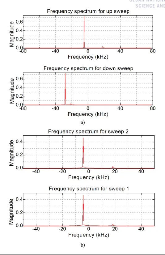
In the case of FMCW modulation, there were four pulse frequencies, two for up and two for down frequencies. Four targets were singled out for the FMCW radar system with four pulse rates. In contrast to FMCW radars, the MFSK system uses pulse frequency and phase difference.
Discussion
The target ranges estimated from MFSK showed worse values than in the case of the FMCW waveform. This work is the first results of the 77 GHz MFSK car radar, it will be developed and completed in the near future. The chirp sequence is proposed to improve the target measurement and estimation accuracy.
Unlike the Doppler radar, the CW radars can extract the absolute range of the target. An introduction to automotive radar applications and the need of the radar sensor to improve the safety of driving tasks was presented in Chapter 1. The detection capability of automotive radar sensors is highly dependent on the modulation waveform, especially in multi-target situations.
In addition, the detection capability of MFSK automotive radars was illustrated through simulations in the comparison with the FMCW radars. The proposed research provides a better solution for current sensors and could be a promising system in the near future. A 77-GHz CMOS automotive radar transceiver with anti-interference function. IEEE Transactions on Circuits and Systems I: Regular Papers.