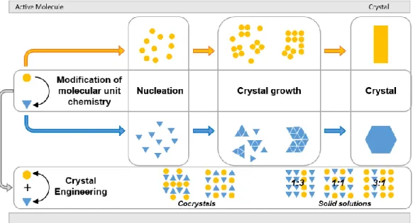
By controlling the crystal structure and morphology of materials, it is possible to improve the production process of products with high added value. Depending on the specific molecular chemistry, the crystal structure and morphology of the material can change. Consequently, the thermodynamic, electronic, optical and catalytic properties depend on the crystal structure and morphology.
In this thesis, the crystal structure and morphology of semiconductor nanomaterials applied in electrochemical energy storage and optoelectronic fields were extensively studied. Chapter 1 provides a brief background on crystallization, including information on internal and external factors that influence crystal structure and morphology during crystallization. In Chapter 3, solvent engineering was used to control crystal structure and morphology by manipulating the crystallization process in perovskite materials.
Overall, these studies demonstrated the design and control strategies for crystal structure and morphology of semiconductor materials.
Introduction
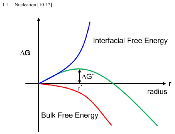
Crystallization
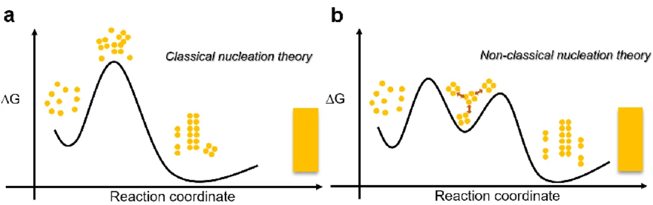
- Nucleation
- Crystal growth
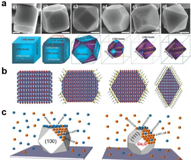
Introduction to Control of Crystal Structure and Morphology
- Chemical modification
- Sovlent engineering
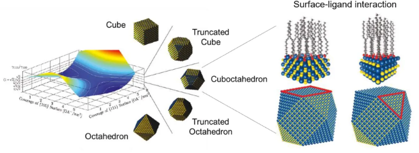
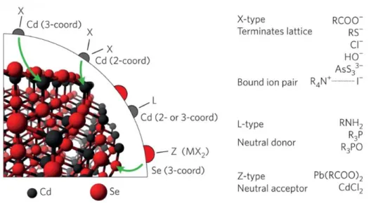
- Ligand interaction
Simulation Methods
- Multiscale simulation
- Morphology model
Crystal Engineering of Hexabenzocoronene Derivatives and C 60 with Ion Storage
- Introduction
- Computational details
- Crystal structure prediction
- Monte Carlo simulation
- Density functional theory calculation
- HOMO and LUMO energy levels
- Results and Discussion
- Contorted hexabenzocoronene (cHBC)
- Fluorinated contorted hexabenzocoronene (F-cHBC)
- cHBC/F-cHBC solid solution
- C 60 /cHBC cocrystal
- Conclusion
- References
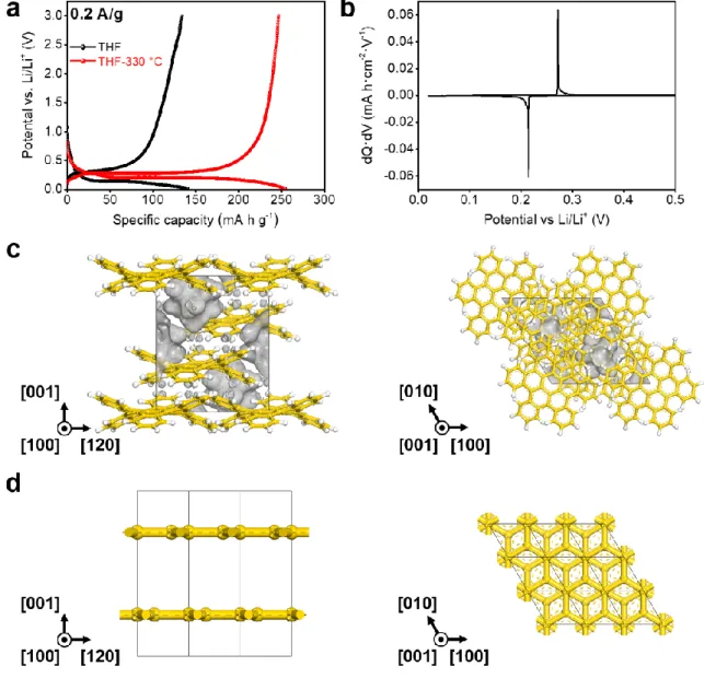
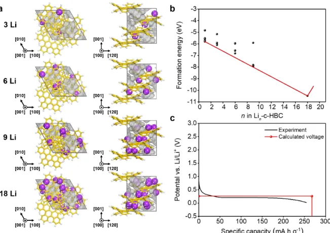
Black dashed arrow: distance between Li ion and fluorine or between Li ion and the center of the bent edge aromatic ring. Inset figures represent projection views of the optimized Pnnm phase of Li-ion inserted C60/cHBC cocrystal along [001] direction. C60 molecules, cHBC molecules, inserted Li ion at stage I, additional inserted Li ion at stage II, and additional inserted Li ion at stage III are gray, yellow, green, cyan, and blue, respectively.
The optimized structure of the Pnnm phase of Li-ion inserted C60/cHBC cocrystal into each phase and enlarged images of the Li-ion insertion site; a) stage I, b) stage II, c) stage III. C60 molecules, cHBC molecules, additionally inserted Li-ion at stage I, additionally inserted Li-ion at stage II, and additionally inserted Li-ion at stage III are gray, yellow, green, cyan, and blue, respectively. The distances between Li-ion and the centroid of the hexagonal or pentagonal aromatic ring of C60 or cHBC molecules and close contact of Li-ion are the black dashed line and the orange line, respectively.
Solvent Engineering of Perovskite Granular Wire with High Photodetectivity
- Introduction
- Computational details
- Growth morphology
- Forcefield parameterization
- Molecular dynamics simulation
- Young’s modulus calculation
- Results and Discussion
- Conclusion
- References
Pb, I, C, N, O and H atoms are represented by dark grey, brown, grey, blue, red and white, respectively. Bulk Pb and I atoms and DMF molecules are shown in dark gray, brown, and green, respectively.
Morphological Engineering of Quantum Dots through Oleate Ligand-ZnSe Shell
Introduction
Among them, research on QDs that can be applied to displays by using a narrow emission line width and emission tip tuning depending on the size of the QDs is ongoing. Unfortunately, the performance of such InP-based QDs is inferior to CdSe-based QDs in many parts, especially in the broad linewidth of emission light in all visible regions, which is represented by full width at half maximum (FWHM). The FWHM of emission light is an important property in displays because it affects the color gamut – in particular, a wider color gamut can be achieved with a narrower FWHM.
However, in the case of InP QDs as the core, the main research has focused on achieving high efficiency to alternate CdSe in the green and red emission range [13–15]. In terms of FWHM, green has a FWHM of approximately 40-45 nm on average, and 36 nm for the narrowest emission [16]. InP/GaP/ZnS core/shell/shell structures that used a GaP buffer layer between the InP core and ZnS shell have been fabricated [18,19].
The QDs exhibited a FWHM of 42 nm and QY of 85%; however, narrower emission was impossible by forming a thicker GaP layer. To coat high-quality ZnSe shells on InP, the addition of ZnSe precursors was finely controlled, and a QY of 50–70% and a FWHM of 38 nm in green and 44 nm in red were achieved [21]. In addition to the previous studies, to induce the more limited effect depending on the morphology for high efficiency, we introduced the heating method which controls the temperature.
In this study, InGaP/ZnSe/ZnS core/shell/shell QDs were obtained by coating a ZnSe shell on the InGaP core with oleate ligand, using a heating method in which ZnSe precursors were added to a low-temperature core solution and then quickly raised to a temperature higher than 300 °C. Thus, tetrahedral QDs with a FWHM of 37 nm, green emission of 532 nm and QY of 85% were obtained. In the experiment, ZnSe with a band gap of 2.7 eV and a lattice parameter of 5.66 Å played the role of a lattice buffer layer between the core and the outer shell in the type-I band offsets.
In addition, this method was applied to red-emitting QDs, and the emission FWHM of more than 60 nm was reduced to 40.4 nm. For the interaction of oleate ligand as a function of temperature, Gibbs free energy calculations were performed to evaluate the morphology depending on the temperature.
Computational details
- Density functional theory calculation
- Gibbs free energy for temperature effect
Results and Discussion
Generally, the change in morphology occurs due to the relative stability of the crystal facet and the adsorption/desorption properties of. In the core/shell structure, the diffraction peaks in the PXRD patterns shifted toward the peak of the ZnSe (i.e., shell material), which were usually located between the core and shell peaks. However, the PXRD peaks of the InGaP/ZnSe core/shell were located at the ZnSe position, indicating that the ZnSe shell was very thick.
The <111> peak was split and the InP core peak also appeared. This phenomenon can be attributed to the high crystallinity of the inner core due to the high temperature annealing during the ZnSe shell coating. This also suggests that high-temperature annealing affects not only the ZnSe shell coating but also the crystallinity of the core itself.
Interplanar distance according to the miller indices of the possible growth surfaces of zinc blende ZnSe. Since the volume of the ZnSe shell occupies most of the nanoparticles, the focus is on the surface structure of the ZnSe shell to investigate the morphology of QDs. Because the ligand consists of two oleate ions, the coverage for ligand adsorption was assumed to be half the number of dangling Se exposed on each surface.
As shown in Figure 4.8, the Gibbs free energy of the (adsorption) binding of Zn(oleate)2 (∆Gbind) to the (111) surface is the strongest, so we can predict that the tetrahedral QD surrounded by the ( 111) surface can be observed. Gstruc is calculated from Eq. 1) and (5), (d) Gibbs free energy for reconstruction of surface (Grec) as a function of the temperature — Grec is calculated from Eq. Interestingly, the (220) surface became the second most stable due to the large contribution of the surface free energy among other energies as shown in Figure 4.9b.
The rate of increase of the <220> peak intensity in the experimental XRD (Figure 4.3) is greater than that found. Although the edge lengths are slightly different in the tetrahedral form, the band gaps are similar, and the FWHM of the PL becomes narrower.
Conclusion
Summary and Future Perspectives
노재영†, 백승민†, 박주현†, 곽상규*, 김상욱*,. 박재현†, 주세훈†, 김윤정†, 박주현, 곽상규*, 안석훈*, 강석주*, "고도전성 리튬 호스트 전극용 유기 반도체 공결정". 많은 분들의 도움과 기도 덕분에 박사학위를 취득할 수 있게 되어 감사한 마음을 전하고 싶습니다.
무엇보다 지도교수이신 곽상규 교수님께 진심으로 감사의 말씀을 전하고 싶습니다. 연구뿐만 아니라 생활 전반에 걸쳐 교수님의 지도 덕분에 더욱 성숙한 사람이 될 수 있었습니다. 교육 기간 동안 공동 연구를 수행할 수 있는 귀중한 기회를 주셔서 감사합니다.
마지막으로, 저의 부족한 영어 실력을 향상시킬 수 있도록 영어 선생님이 되어주신 Kris 님께 이 기회를 빌어 감사의 말씀을 전하고 싶습니다. 박사과정의 어려움을 공감해주는 그들의 모습에 더욱 위로와 용기를 얻을 수 있었습니다. 결국, 저는 세상에서 가장 소중한 가족의 끊임없는 지지와 희생 덕분에 박사과정을 성공적으로 마칠 수 있었습니다.
누구보다 여성스럽고 사랑이 많으신 우리 할머니께도 감사 인사를 전하고 싶습니다. 건강하게 오래오래 내 곁에 있어주셨으면 좋겠습니다. 앞으로 다가올 새로운 미래를 두려워하지 말고 포기하지 말고 지금처럼 도전적인 자세를 유지하라고 말씀드리고 싶습니다.
지금까지 많은 분들의 도움으로 성장했다고 생각합니다. 여러분의 성원에 힘입어 앞으로도 더욱 발전하는 훌륭한 연구자가 되도록 최선을 다하겠습니다.