Subject
1. What relation do mobility of electron and resistivity have?
2. Contribution of diffusion of excess carrier in current 3. Carrier injection and carrier action
1. direct gap semiconductor and indirect semiconductor 2. recombination lifetime
3. quasi-Fermi level
4. How does current change while considering diffusion and
recombination ?
Drift
Diffusion
Generation-Recombination
Equations of State
3
Drift
• Definition-Visualization
Charged-particle motion in response to electric field
An electric field tends to accelerate the +q charged holes in the direction of the electric field and the –q charged electrons in the opposite direction
Collisions with impurity atoms and thermally agitated lattice atoms
Repeated periods of acceleration and subsequent decelerating collisions
Measurable quantities are macroscopic observables that reflect the average or overall motion of the carriers
The drifting motion is actually superimposed upon the always- present thermal motion.
The thermal motion of the carriers is completely random and therefore averages out to zero, does not contribute to current
5
• Drift Current
I (current) = the charge per unit time crossing a plane oriented normal to the direction of flow
(a) Motion of carriers within a biased semiconductor bar; (b) drifting hole on a microscopic or atomic scale; (c) carrier drift on a macroscopic scale
Thermal motion of carrier
Expanded view of a biased p-type semiconductor bar of cross-sectional area A
... All holes this distance back from the normal plane will cross the plane in a time
... All holes in this volume will cross the plane in a time
d d
d d
v t v
t
v tA t
pv tA
... Holes crossing the plane in a time ... Charge crossing the plane in a time
d
t
qpv tA t
7 P drift d
P drift
qpv
dJ
The vd is proportional to E at low electric fields, while at high electric fields vd saturates and becomes independent of E
sat0. . . 0 0
d 1/ . . .
0 sat
1 v
vv
E E
E
E E
where for holes and for electrons, is the constant of
proportionality between vd and E at low to moderate electric fields, and is the limiting or saturation velocity
vsat
In the low field limit
v
d
0E
P drift
q
pp
J E
N drift
q n
nJ E q , v
d
nE , J
N drift| qnv
d
1
2
09
• Mobility
Mobility is very important parameter in characterizing transport due to drift
Unit: cm2/Vs
Varies inversely with the amount of scattering (i) Lattice scattering
(ii) Ionized impurity scattering
Displacement of atoms leads to lattice scattering
The internal field associated with the stationary array of atoms is already taken into account in
, where is the mean free time and is the conductivity effective mass
The number of collisions decreases varies inversely with the amount of scattering
/
*q m
m
*m*
Room temperature carrier mobilities as a function of the dopant
11
Temperature dependence
Low doping limit: Decreasing temperature causes an ever-
decreasing thermal agitation of the atoms, which decreases the lattice scattering
Higher doping: Ionized impurities become more effective in deflecting the charged carriers as the temperature and hence the speed of the carriers decreases
Temperature dependence of electron mobility in Si for dopings ranging
13
Resistivity () is defined as the proportionality constant between the electric field and the total current per unit area
J E
1
J E E
=1/: conductivitydrift
N drift
P drift q (
nn
pp )
J J J E
n p
1
( )
q n p
n D
1 ... n type semiconductor
q N
p A
1 ... p type semiconductor
q N
Resistivity versus impurity
concentration at 300 K in Si
15
• Band Bending
When exists the band energies become a function of position
If an energy of precisely EG is added to break an atom-atom bond, the created electron and hole
energies would be Ec and Ev,
respectively, and the created carriers would be effectively motionless
motionless
E-Ec= K.E. of the electrons
Ev-E= K.E. of the holes
The potential energy of a –q charged particle is
P.E. qV
c ref
P.E.
E Ec ref
P.E.
E Ec ref
1 ( )
V E E
q
dV
E
17
By definition,
V E
dV
dx E
c v i
1 dE 1 dE 1 dE
q dx q dx q dx
E
In one dimension,
Diffusion
• Definition-Visualization
Diffusion is a process whereby
particles tend to spread out or redistribute as a result of their random thermal
motion, migrating on a macroscopic scale from regions of high concentration into region of low concentration
19
• Diffusion and Total Currents
Diffusion Currents: The greater the concentration gradient, the larger the flux
Using Fick’s law,
] /
[# cm
2s D
F
Diffusion constant
P diff P
N diff N
qD p qD n
J
J
Total currents
P P drift P diff p P
N N drift N diff n N
drift diffusion q p qD p
q n qD n
J J J
J J J
E
E
Total particle currents
N P
J J J
s cm
D ] /
[
2+
21
• Relating Diffusion coefficients/Mobilities
Einstein relationship
Consider a nonuniformly doped semiconductor under equilibrium
Constancy of the Fermi Level: nonuniformly doped n-type
semiconductor as an example
dE
F/ dx dE
= 0
F/ dy dE
F/ dz 0
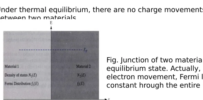
Under thermal equilibrium, there are no charge movements between two materials,
Also, the rate of electron movement from material 2 to material 1 is in proportion to
Under equilibrium condition, these terms are equal. So, f1(E) = f2(E) and EF1 = EF2
The rate of electron movement from material 1 to material 2 is in proportion to
Fig. Junction of two materials in
equilibrium state. Actually, there is no electron movement, Fermi level should be constant hrough the entire material.
23
Under equilibrium conditions
N P
0
N P0
J J J J = J
p P
n N
for nonuniform doping 0 and
or for uniform doping 0
q p qD p
q n qD n
p n
E E E
Einstein relationship:
Nondegenerate, nonuniformly doped semiconductor,Under equilibrium conditions, and focusing on the electrons,
N drift N diff n N
dn 0
J J q n qD
dx
E
1 dE
i q dx
E n n e
i (EFEi) /kT&
= -
Electron diffusion current flowing in the +x direction “Built- in” electric field in the –x direction drift current in the –x direction
With dEF/dx=0,
F i
( ) /
i E E kT i
n dE
dn q
e n
dx kT dx kT
E
Substituting
n N
( ) ( ) q 0
qn qn D
kT
E E
N n
Einstein relationship for electrons D kT
q
P p
Einstein relationship for holes D kT
q
Einstein relationship is valid even under nonequilibrium
Slightly modified forms result for degenerate materials
25
• Definition-Visualization
When a semiconductor is perturbed an excess or deficit in the carrier concentrations Recombination-generation
Recombination: a process whereby electrons and holes (carriers) are annihilated or destroyed
Generation: a process whereby electrons and holes are created
• Band-to-Band Recombination
The direct annihilation of an electron and a hole the production of a photon (light)
• R-G Center Recombination
R-G centers are lattice defects or impurity atoms (Au)
The most important property of the R-G centers is the introduction of allowed electronic levels near the center of the band gap (ET)
Two-step process
R-G center recombination (or indirect recombination) typically releases thermal energy (heat) or, equivalently, produces lattice vibration
27
Near-midgap energy levels introduced by some common impurities in Si
• Generation Processes
thermal energy > EG direct thermal generation
light with an energy > EG photogeneration
The thermally assisted generation of carriers with R-G centers
29
Impact ionization
e-h is produced as a results of energy released when a highly energetic carrier collide with the lattice
High -field regions
• Momentum Considerations
One need be concerned only with the dorminat process
Crystal momentum in addition to energy must be conserved.
The momentum of an electron in an energy band can assume only certain quantized values.
where k is a parameter proportional to the electron momentum
31
Si, Ge GaAs
Photons, being massless entities, carry very little momentum, and a photon-assisted transition is
essentially vertical on the E-k plot
The thermal energy associated with lattice vibrations (phonons) is very small (in the 10- 50 meV range), whereas the phonon
momentum is comparatively large. A phonon- assisted transition is essentially horizontal on the E-k plot. The emission of a photon must be accompanied by the emission or
Photons: light
Phonons: lattice vibration quanta
33
• R-G Statistics
It is the time rate of change in the carrier concentrations (n/t, p
t) that must be specified
B-to-B recombination is totally negligible compared to R-G center recombination in Si
Even in direct materials, the R-G center mechanism is often the dominant process.
• Indirect Thermal Recombination-Generation
n
0, p
0…. carrier concentrations when equilibrium conditions prevail
n, p ……. carrier concentrations under arbitrary conditions
n=n-n
0… deviations in the carrier concentrations from their equilibrium values
p=p-p
0…
N
T………. number of R-G centers/cm
3material type
p a in p
p p
n
material type
n an in
n n
n p
implies injection
level low
0 0
,
,
35
where n= p=109 cm-3
Although the majority carrier concentration remains essentially unperturbed under low-level injection, the minority carrier
concentration can increase by many orders of magnitude.
excess carrier
p p
p p
cm N
n p
n n
n n
cm N
n
D i
D
0 3
6 2
0
0 0
3 14
0
10 /
10
p
The greater the number of filled R-G centers, the greater the probability of a hole annihilating transition and the faster the rate of recombination
Under equilibrium, essentially all of the R-G centers are filled with electrons because EF>>ET
With , electrons always vastly outnumber holes and
rapidly fill R-G levels that become vacant # of filled centers during the relaxation NT
The number of hole-annihilating transitions should increase almost linearly with the number of holes
Introducing a proportionality constant, cp,
n
0p
T R
t N
p
37
The recombination and generation rates must precisely balance under equilibrium conditions, or p/t|G = p/t|G-equilibrium=- p/t|R-equilibrium , so
p T 0 G
p c N p t
p T 0
i thermalR G R G
( )
p p p
c N p p
t
t t
p T i thermal
R G
or p for holes in an type material
c N p n
t
n T i thermal
R G
for electrons in a type material
n c N n p
t
The net rate
An analogous set of arguments yields
um equiliburi G
G
t
p t
p
cn and cp are referred to as the capture coefficients
cpNT and cnNT must have units of 1/time
p n
p T n T
1 1
c N c N
i thermalR G p
for holes in an type material
p p
t
n
i thermalR G n
for electrons in a type material
n n
t
p
These are the excess minority carrier life times.
39
• Continuity Equations
Carrier action – whether it be drift, diffusion, indirect or direct thermal recombination, indirect or direct generation, or some other type of carrier action – gives rise to a change in the carrier
concentrations with time
Let’s combine all the mechanisms
thermal other processes
drift diff R-G (light, etc.)
thermal other processes
drift diff R-G (light, etc.)
n n n n n
t t t t t
p p p p p
t t t t t
processes other G
thermalR P
processes other G
thermalR N
Pz P Px Py
diff drift
Nz N Nx Ny
diff drift
t p t
J p q
t p
t n t
J n q
t n
q J z
J y
J x
J q
t p t
p
q J z
J y
J x
J q
t n t
n
1 1
) 1 1 (
) 1
1 (
x
x x
J x
J q t
p
p px x x n
) (
) 1 (
t p x
t p x
x q
q v p x
J
q
1
t v x
• Minority Carrier Diffusion Equations
Simplifying assumptions:(1) One-dimensional
(2) The analysis is limited or restricted to minority carriers (3) .—no drift current term- so it is called Diffusion Equations.
(4) The equilibrium minority carrier concentrations are not a function of position
(5) Low level injection
(6) Indirect thermal R-G is the dominant thermal R-G mechanism (7) There are no “other processes”, except possibly
photogeneration
0 E
0 0
( ),
0 0( )
n n x p p x
N N
1 1 J
q q x
J
N n N N
n n
J q n qD qD
x x
E
43
n n
0 n
n
0n n n
x x x x
2
N N 2
1 n
q D x
J
With low level injection,
thermal n
R-G
n n
t
other L processes
n G
t
GL=0 without illumination The equilibrium electron concentration is never a function of time
n
0n n n
t t t t
2
p p p
N 2 L
n 2
n n n
P 2 L
p
n n n
D G
t x
p p p
D G
t x
Minority carrier
diffusion equations
45
No concentration gradient or no diffusion current
2 2
2 p
0
2 n0
N P
n p
D D
x x
No drift current or no further simplification
E 0
No thermal R-G
0 0
p n
n p
n p
No light
L
0
G
0 0
p n
n p
t t
Steady state
is set equal to zero. G
LL P
n n
P
n
p G
x D p
t
p
2 2
L P
n
n
p G
dt p
d
t P
n
n
t p e
p ( ) ( 0 )
/
Therefore, the solution is
p p p
N 2 L
n 2
n n n
P 2 L
p
n n n
D G
t x
p p p
D G
t x
Sample Problem No.1 : A uniformly donor-doped silicon wafer
maintained at room temperature is suddenly illuminated with light at time t=0. Assuming , , and a light-
induced creation of electrons and holes per
throughout the semiconductor, determine for .
3 15
/
10 cm
N
D
P 10
6sec
10
17cm
3 sec
) (t p
n t 0
Solution :
Step1 – Si, T=300K, , and at all points inside the semiconductor.
Step2 -
with uniform doping, the equilibrium and values are the same
everywhere throughout the semiconductor.
3 15
/
10 cm
N
D G
L 10
17/ cm
3 sec
3 15
0 3
10
/ , , 10 /
10 cm N n n N cm
n
i
D
i
D
3 5
2
0
n / N 10 / cm
p
i D
Step3 – Prior to t=0, equilibrium conditions prevail and illumination -> increase.
excess carrier number ↑ -> thermal recombination rate ↑
∴ light generation and thermal recombination rates must balance under steady state conditions, we can even state
or if low-level injection prevails.
Step4 –
the boundary condition
0
p
np
n
P n
L
p t
G ( ) / p
n( t ) p
n|max G
L
P3 15
0 3
11 max
|
G 10 / cm n 10 / cm
p
n
L P
L P
n P n
n
p G
x D p
t
p
2 2
0
| )
(
0
p
nt
tordinary differential equation and simplifies to
The general solution is
Applying the boundary condition yields
and
L P
n
n
p G
dt p
d
t P
P L
n
t G Ae
p ( )
/
P
G
LA
solution )
1 ( )
(
/
p
nt G
L
Pe
t PStep5 – A plot of the solution equation is shown below.
Note that, starts from zero at t=0 and eventually saturates at after a few .
) (t p
n
P
G
L
Porder by the pulse train pictured below.
) 1
( )
(
L P t/ Pn
t G e
p
The upper equation approximately describes the carrier build-up during a light pulse.
However, the stroboscope light pulses have a duration of compared to a minority carrier lifetime of .
With , one sees only the very first portion of the Fig.
3.25 transient before the light is turned off and the semiconductor is allowed to decay back to equilibrium.
The light-off expression derivation closely parallels the light- on sample problem solution.
Exceptions -> at the beginning of the light-off = at the end of the light-on.
sec 1
on
t sec 150
P 1
/
P
t
on
) (t p
n
p
n p
n55
Sample problem 2: As shown below, the x=0 end of a uniformly doped semi-infinite bar of silicon with ND=1015 cm-3 is illuminated so as to create pn0=1010 cm-3 excess holes at x=0. The wavelength of the illumination is such that no light penetrates into the interior (x>0) of the bar. Determine pn(x).
Solution: at x=0, pn(0)= pn0= 10 cm , and pn 0 as x
The light first creates excess carriers right at x=0
GL=0 for x>0
Diffusion and recombination
As the diffusing holes move into the bar their numbers are reduced by recombination
Under steady state conditions it is reasonable to expect an excess distribution of holes near x=0, with pn(x) monotonically decreasing from pn0 at x=0 to pn0= 0 as x
Can we ignore the drift current? E 0 ? Yes because 1>Excess hole pile-up is very small , here
2> Also the majority carriers redistribute in such a way to partly cancel the minority carrier charge. Thus use of diffusion eq. is
justified.
( p
n max n
i)
57
The general solution
P P
/ /
n
( )
x L x Lp x Ae
Be
whereL
p D
p p
exp(x/Lp) as x
B 0
With x=0,
A p
n0/ P
n
( )
n0 x Lsolution p x p e
2
n n
p 2
p
0 for 0
d p p
D x
dx
n x
0
p
n x 0 n x 0 n0
p
p
p
So---Under steady state conditions with GL=0 for x > 0
N N n
L D
LP and LN represent the average distance minority carriers can diffuse into a sea of majority carriers before being annihilated
The average position of the excess minority carriers inside the semiconductor bar is
n n P
0
( )
0( )
x
x p x dx
p x dx L
Supplemental Concepts
• Diffusion Lengths
minority carrier diffusion lengths
P P p
L D
59
• Quasi-Fermi Levels
Quasi-Fermi levels are energy levels used to specify the carrier concentrations under nonequilibrium conditions The convenience of being able to deduce the carrier concentrations by inspection from the energy band diagram is extended to
nonequilibrium conditions through the use of quasi-Fermi levels by introducing FN and FP
Equilibrium conditions Nonequilibrium conditions
N i
i P
( ) /
N i
( ) /
P i
or ln
or ln
F E kT i
i
E F kT i
n n e F E kT n
n
p n e F E kT p
n
11 -3 11 -3 15 -3
10 cm ,
010 cm , 10 cm
n L p
p G p p p n
n n
0 10
15cm
3