Computer
Networking: A Top Down Approach
A note on the use of these Powerpoint slides:
We re making these slides freely available to all (faculty, students, readers).
They’re in PowerPoint form so you see the animations; and can add, modify, and delete slides (including this one) and slide content to suit your needs.
They obviously represent a lot of work on our part. In return for use, we only ask the following:
§ If you use these slides (e.g., in a class) that you mention their source (after all, we d like people to use our book!)
§ If you post any slides on a www site, that you note that they are adapted from (or perhaps identical to) our slides, and note our copyright of this material.
Thanks and enjoy! JFK/KWR All material copyright 1996-2016
J.F Kurose and K.W. Ross, All Rights Reserved
7 th edition
Jim Kurose, Keith Ross
Pearson/Addison Wesley April 2016
Chapter 5
Network Layer:
The Control Plane
Chapter 5: network layer control plane
chapter goals: understand principles behind network control plane
§ traditional _______ algorithms
§ _______ _______ _______ Protocol
§ network management
and their instantiation, implementation in the Internet:
§ OSPF, BGP, OpenFlow, ODL and ONOS controllers, ICMP, SNMP
5-2
Network Layer: Control Plane
5.1 introduction
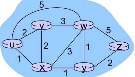
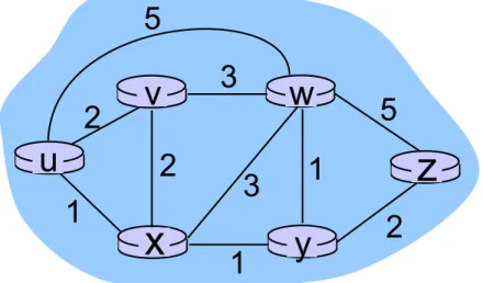
5.2 routing protocols
§ link state
§ distance vector
5.3 intra-AS routing in the Internet: OSPF
5.4 routing among the ISPs:
BGP
5.6 ICMP: The Internet Control Message Protocol
5.7 Network management and SNMP
Chapter 5: outline
Network-layer functions
§ _______ : move packets from router s input to
appropriate router output _______ plane _______ plane
Two approaches to structuring network control plane:
§ per-router control (traditional)
§ logically centralized control (software defined networking)
Recall: two network-layer functions:
5-4 Network Layer: Control Plane
§ _______ : determine route
taken by packets from source
to destination
Per-router control plane
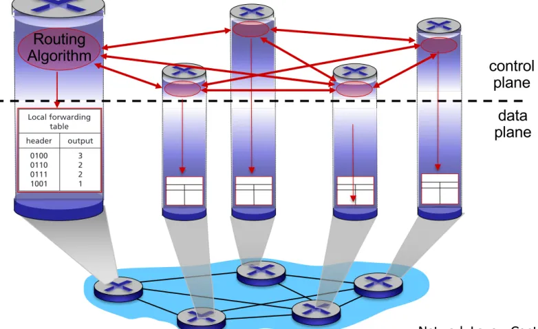
Routing Algorithm
_______ routing algorithm components in _______ and
_______ router _______ with each other in control plane to compute forwarding tables
plane data control
plane
4.1 • OVERVIEW OF NETWORK LAYER 309
tables. In this example, a routing algorithm runs in each and every router and both forwarding and routing functions are contained within a router. As we’ll see in Sec- tions 5.3 and 5.4, the routing algorithm function in one router communicates with the routing algorithm function in other routers to compute the values for its forward- ing table. How is this communication performed? By exchanging routing messages containing routing information according to a routing protocol! We’ll cover routing algorithms and protocols in Sections 5.2 through 5.4.
The distinct and different purposes of the forwarding and routing functions can be further illustrated by considering the hypothetical (and unrealistic, but technically feasible) case of a network in which all forwarding tables are configured directly by human network operators physically present at the routers. In this case, no routing protocols would be required! Of course, the human operators would need to interact with each other to ensure that the forwarding tables were configured in such a way that packets reached their intended destinations. It’s also likely that human configu- ration would be more error-prone and much slower to respond to changes in the net- work topology than a routing protocol. We’re thus fortunate that all networks have both a forwarding and a routing function!
Values in arriving packet’s header
1
3 2 Local forwarding
table header
0100 01100111 1001
1101
3 22 1 output Control plane
Data plane
Routing algorithm
Figure 4.2 ♦ Routing algorithms determine values in forward tables